EP0773632A1 - Radio émetteur-récepteur - Google Patents
Radio émetteur-récepteur Download PDFInfo
- Publication number
- EP0773632A1 EP0773632A1 EP95117608A EP95117608A EP0773632A1 EP 0773632 A1 EP0773632 A1 EP 0773632A1 EP 95117608 A EP95117608 A EP 95117608A EP 95117608 A EP95117608 A EP 95117608A EP 0773632 A1 EP0773632 A1 EP 0773632A1
- Authority
- EP
- European Patent Office
- Prior art keywords
- receiving device
- sleeve
- rod
- housing
- radio transmitting
- Prior art date
- Legal status (The legal status is an assumption and is not a legal conclusion. Google has not performed a legal analysis and makes no representation as to the accuracy of the status listed.)
- Granted
Links
- 230000005291 magnetic effect Effects 0.000 claims abstract description 14
- 230000005294 ferromagnetic effect Effects 0.000 claims description 60
- 239000003302 ferromagnetic material Substances 0.000 claims description 2
- 238000010276 construction Methods 0.000 description 5
- 239000012777 electrically insulating material Substances 0.000 description 3
- 238000012986 modification Methods 0.000 description 3
- 230000004048 modification Effects 0.000 description 3
- 230000000694 effects Effects 0.000 description 2
- 230000004907 flux Effects 0.000 description 2
- 239000000463 material Substances 0.000 description 2
- 238000005452 bending Methods 0.000 description 1
- 238000006073 displacement reaction Methods 0.000 description 1
- 239000013013 elastic material Substances 0.000 description 1
- 238000003780 insertion Methods 0.000 description 1
- 230000037431 insertion Effects 0.000 description 1
- 230000007774 longterm Effects 0.000 description 1
- 239000002184 metal Substances 0.000 description 1
- 238000000034 method Methods 0.000 description 1
Images





Classifications
-
- H—ELECTRICITY
- H01—ELECTRIC ELEMENTS
- H01Q—ANTENNAS, i.e. RADIO AERIALS
- H01Q1/00—Details of, or arrangements associated with, antennas
- H01Q1/08—Means for collapsing antennas or parts thereof
- H01Q1/10—Telescopic elements
- H01Q1/103—Latching means; ensuring extension or retraction thereof
Definitions
- the invention relates to a radio transmitting and receiving device according to the preamble of Patent Claim 1.
- a housing of the device can be equipped with an antenna which has a rod which can be retracted and extended through an opening in the housing.
- the invention is based on the object of providing a radio transmitting and receiving device of the type mentioned at the beginning in which the antenna is made easier to handle.
- a radio transmitting and receiving device is characterized in that the rod can be secured in its respective end position by a magnetic force.
- the rod after first having been displaced manually, is pulled into its end position by the magnetic force, and secured there.
- This relates both to the state in which the rod is completely pulled out of the device and the state in which it has been completely pushed into the device.
- wear phenomena in the region of the guides of the rod only play a subordinate role so that even after a very large number of displacements of the rod it can always be held precisely in its end position.
- This involves reliable positioning of contact elements, which always ensures statisfactory connection of the antenna to the circuit of the device.
- a first embodiment of the present invention is characterized in that the rod has ferromagnetic sections in the regions of its two ends and a fixed magnetic arrangement, which attracts the rod in order to secure it in its respective end position via in each case one of the ferromagnetic sections, is present in the housing.
- a second embodiment of the present invention is characterized in that the rod has a ferromagnetic section in the region of its lower end (closer to the housing) and two fixed magnetic arrangements are present in the housing in a distance along the length of the rod.
- a third embodiment of the present invention is characterized in that the rod has magnet arrangements in the region of its two ends and a fixed ferromagnetic section is present in the housing to be attracted by one of the magnet arrangements, respectively.
- a fourth embodiment of the present invention is characterized in that the rod has a magnet arrangement in the region of its lower end (closer to the housing) and two fixed ferromagnetic sections are present in the housing in a distance along the length of the rod.
- the rod is electrically connected to a transmitting and receiving circuit of the device via a magnet arrangement/ferromagnetic section.
- the ferromagnetic sections/magnet arrangements assume the function of contact elements on the rod so that separate contact elements can be dispensed with, which simplifies the design of the antenna.
- the rod is slidingly mounted in an elastic sleeve which is permanently inserted into the opening in the housing.
- the sleeve preferably has a wall region which protrudes outwards in elastic fashion and is bounded by two axial slots which start from the rear end side of the sleeve.
- the sleeve can thus be simply inserted into the opening in the housing which, for this purpose, has an axial groove for receiving the outwardly protruding wall region of the sleeve, the axial grove being closed at the external side of the opening in the housing.
- the sleeve can thus be inserted into the opening in the housing in a locking fashion.
- the housing can have a channel which, when the sleeve is inserted, runs essentially perpendicularly towards that wall region of the sleeve which protrudes outwards in an elastic fashion, so that it is possible to press inwards the outwardly protruding wall region of the sleeve using a pin which is passed through the channel.
- the sleeve can be pulled out of the opening in the housing counter to its insertion direction, and the rod can be pulled with it.
- the side walls of the axial groove can also be bevelled in the circumferential direction of the opening in the housing.
- the sleeve only needs to be rotated in order to press its outwardly projecting wall region inwards so that the sleeve can then also be removed from the opening in the housing.
- it can have a collar which comes to rest on the outside of the housing.
- the magnet arrangement can receive the rod in a sliding manner and be held securely in a sleeve which is screwed into the opening in the housing.
- the radio transmitting and receiving device itself can be of any desired design and in particular may also take the form of a portable device. In the latter case, it may be for example a portable or cordless telephone or radiotelephone.
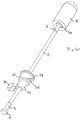
- Fig. 1 relates to a first exemplary embodiment of a radio transmitting and receiving device according to the invention. Here, a partial detail is shown in the region of a rod antenna.
- the rod antenna bears the reference symbol 1 and has a rod 2 which consists of an elastic and electrically insulating material, for example plastic. Inside the rod 2 an antenna feeder 3 runs in the longitudinal direction, in a partial region of the rod 2. The antenna feeder 3 is shown in Fig. 1 by broken lines and is encased by the material of the rod 2.
- the antenna feeder 3 is connected in an electrically conductive way at its housing-side end to a first ferromagnetic section 4.
- a guide section 5 adjoins the first ferromagnetic section 4 in the direction towards the free end of the rod antenna 1.
- This guide section 5 can consist of any desired material, that is to say also of ferromagnetic material, and can be integrally connected to the first ferromagnetic section 4.
- the diameter of the guide section 5 is greater than that of the rod 2, while the diameter of the first ferromagnetic section 4 is greater than that of the guide section 5.
- the rod 2 has a second ferromagnetic section 6.
- this second ferromagnetic section 6 is not connected to the antenna feeder 3 which ends just before the second ferromagnetic section 6.
- the second ferromagnetic section 6 has a diameter which corresponds to the diameter of the guide section 5.
- the second ferromagnetic section 6 bears a further antenna component 7 which contains a helix antenna for example in its interior, which helix antenna is connected in an electrically conductive fashion to the second ferromagnetic section 6.
- the further antenna component 7 can be a cast plastic element.
- the rod antenna 1 is mounted on a housing 8 of the radio transmitting and receiving device in such a was that it can be pushed into the housing 8 as far as the further antenna component 7. It can be pulled out of the housing 8 again by pulling manually on the further antenna component 7. However, in such a case the first ferromagnetic section 4 remains inside the housing 8 while the guide section 5 remains inside a wall 9 of the housing.
- the housing 8 In order to retract and extend the rod into the housing 8 and out of it, there is a cylindrical through-opening 10 or opening in the housing inside the wall 9. An elastic sleeve 11 is inserted into this through-opening 10 in a clamping fashion, the said sleeve 11 itself receiving the rod 2.
- the internal diameter of the sleeve 11 corresponds to the external diameter of the guide section 5 and of the second ferromagnetic section 6.
- the external diameter of the sleeve 11 corresponds to the internal diameter of the through-opening 10.
- a magnetic arrangement 12 is permanently attached to the inside of the housing wall 9.
- This magnet arrangement 12 comprises a permanent magnet 13 and two pole plates 14 and 15 on opposite sides of the permanent magnet 13.
- the pole plates 14 and 15 each come to rest in a plane which extends perpendicularly to the longitudinal direction of the through-opening 10.
- the pole plates 14 and 15 are of concave construction on their end side facing the through-opening 10, such that their end faces extend concentrically to the longitudinal axis of the through-opening 10 there.
- the radius of curvature of the concave end sides corresponds to the radius of the first ferromagnetic section 4.
- the housing 8 of the radio transmitting and receiving device has a rear wall 16 on whose inside for example a circuit board 17 is mounted, on which a transmitting and receiving circuit (not illustrated in greater detail) of the device according to the invention is entirely or partially located.
- a transmitting and receiving circuit (not illustrated in greater detail) of the device according to the invention is entirely or partially located.
- an elastic spring contact 18 is attached to the circuit board 17, which spring contact 18 presses against one of the pole plates, for example against the rear end face of the pole plate 15.
- the sleeve 11 If the sleeve 11 is inserted into the through-opening 10 in a permanent or clamping fashion and if the sleeve 11 receives the rod 2, the latter can be pushed into the housing 8 with the exception of the further antenna component 7.
- the second ferromagnetic section 6 comes to rest inside the sleeve 11, the length of the second ferromagnetic section 6 being selected such that this also comes to rest in the region of the two pole plates 14 and 15 when the further antenna component 7 strikes against the wall 9.
- the magnetic flux of the magnet 13 is thus directed via the pole plates 14 and 15 through the second ferromagnetic section 6 so that in this position the rod antenna 1 is secured by the magnet arrangement 12.
- the second ferromagnetic section 6 fits into the interior of the sleeve 11 whose internal diameter is only slightly larger than the external diameter of the second ferromagnetic section 6.
- the antenna device which is present inside the further antenna component 7 is now electrically connected to the transmitting and receiving circuit on the circuit board 17 via the second ferromagnetic section 6, the magnet arrangement 12 or the pole plate 15 and the spring contact 18. In this state, the circuit can receive a signal coming from the outside.
- the guide section 5 moves into the interior of the sleeve 11 while at the same time the first ferromagnetic section 4 comes to rest in the region of the two pole plates 14 and 15.
- the guide section 5 is guided through the sleeve 11 whose internal diameter is only slightly larger than the external diameter of the guide section 5 while the first ferromagnetic section 4 prevents the rod antenna 1 being pulled out completely from the housing 8.
- the first ferromagnetic section 4 has an external diameter which, as already mentioned, is larger than the external diameter of the guide section 5 so that the first ferromagnetic section 4 strikes against the end-side edge of the sleeve 11 and thus serves as a stop.
- the antenna feeder 3 is electrically connected to the transmitting and receiving circuit on the circuit board 17, if appropriate via the electrically conductive guide section 5, the first ferromagnetic section 4, the magnet arrangement 12 or the pole plate 15 and the spring contact 18. It is now possible to transmit and receive in order to make a call. If the guide section 5 were to consist of electrically insulating material, the antenna feeder 3 could pass through it and only be electrically connected to the first ferromagnetic section 4.
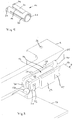
- Figs. 2 and 3 show, in an enlarged view, the sleeve 11 and the respective section of the housing 8, identical components to those in Fig. 1 being provided with the same reference symbols and not being described again.
- the sleeve 11 has a plurality of axial slots which start from different end sides of the sleeve 11.
- Three axial slots 19, 20 and 21 can be seen in Fig. 2, the axial slot 19 starting from the outer end side of the sleeve 11 while the axial slots 20 and 21 start from the inner end side of the sleeve 11.
- a wall region 22, which projects outwards in an elastic fashion, of the sleeve 11 is maintained by providing a further axial slot 23, which can only be seen in Figs. 4 and 5.
- This further axial slot 23 also starts from the outer end side of the sleeve 11 and is adjacent to the axial slot 19.
- Both slots 19 and 23 extend not quite as far as the inner end side of the sleeve 11 so that the sleeve wall lying between them can be bent outwards in order to form the elastic wall region 22.
- This wall region 22 extends not quite as far as the outer end side of the sleeve 11.
- the collar 24 is provided on this outer end side of the sleeve 11 (on the left in Fig. 2), the said collar 24 preventing the sleeve 11 dropping through the through-opening 10 when it is inserted into it. Instead, the collar 24 strikes against the outside of the wall 9, thus positioning the sleeve 11 in the axial direction within the through-opening 10.
- the sleeve 11 has a certain degree of elasticity in the radial direction owing to the axial slots 19, 20, 21 and 23 which start from various end sides of the sleeve 11 and also to a further axial slot. It can thus be pressed over the first ferromagnetic section 4 of the rod antenna, the external diameter of which ferromagnetic section 4 is larger than the internal diameter of the sleeve 11 when it is in the radially extended state. In the non-radially extended state the internal diameter of the sleeve 11 corresponds to the external diameter of the guide section 5 or to the external diameter of the second ferromagnetic section 6.
- the sleeve 11 When the sleeve 11 receives the rod 2, it can be pressed from outside into the through-opening 10 until the collar 24 strikes against the outside of the wall 9. While a prescribed rotational position of the sleeve 11 is complied with, the initially inwardly pressed elastic wall region 22 then jumps into an axial groove 25 which is located inside the housing wall 9 on the side of the through-opening 10. This axial groove 25 extends from the inside of the wall 9 in the direction of its outside but without reaching the latter.
- the length of the axial groove 25 is dimensioned here such that when the sleeve 11 is completely inserted into the through-opening 10 the end side, pointing in the direction of the outer end side of the sleeve 11, of the elastic wall region 22 strikes against the end of the axial groove 25. In this way, axial securing of the sleeve 11 within the wall 9 is achieved.
- the elastic wall region 22 must be pressed in the direction of the centre of the sleeve 11.
- this channel 26 ends above the free end of the elastic wall region 22 so that the latter can be pressed downwards or into the interior of the sleeve 11, for example by means of a thin rod which is passed through the channel 26.
- the sleeve 11 can then be pulled out of the through-opening 10 in the direction of its outer end side, and the rod antenna 1 can be pulled with it.
- Fig. 3 shows the attachment of the magnet arrangement 12 in the interior of the housing 8.
- Two inwardly pointing projections 27, 28 are provided on the inside of the wall 9 and a clamp 29 is provided on the rear wall 16 of the housing 8 in order to receive the magnet arrangement 12 between them.
- arms 30, 31 on the rear of the pole plates 14, 15 engage around a web 32 which is also attached to the rear wall 16 of the housing 8 in order to prevent the magnet arrangement being displaced in the direction of the through-opening 10.
- Figs. 4 and 5 show once more the sleeve 11 in various rotational positions in enlarged view. Identical elements to those in Fig. 2 are provided here with the same reference symbols and are not described again. As is shown in particular by Fig. 5, a further axial slot 33, which comes to rest between the axial slots 20 and 21 but starts from the outer end side of the sleeve 11, on the left in Fig. 5, is also provided.
- the sleeve 11 itself can consist of metal or plastic.
- the housing 8, and in particular the wall 9 consist of electrically insulating material, for example of plastic also.
- FIG. 6 A second exemplary embodiment of the invention is shown by Figs. 6 to 17.
- identical elements to those in Figs. 1 to 5 are again provided with the same reference symbols.
- Figs. 6 and 7 the antenna arrangement is shown with an attachment device in various rotational positions in order to make their design clearer.
- the rod antenna 1 has a rod 2 in whose interior the antenna feeder 3 runs.
- the rod 2 now has an external diameter which corresponds to the external diameter of the guide section 5 or of the second ferromagnetic section 6.
- the first ferromagnetic section 4 is of relatively short construction in the axial direction and again has an external diameter which is larger than the external diameter of the guide section 5.
- the second ferromagnetic section bears the further antenna component 7, it is being possible for a ferromagnetic disc 34, similar to the first ferromagnetic section 4, to be present on the underside of the further antenna component 7, the said disc 34 being connected to the second ferromagnetic section 6 in an electrically conductive fashion.
- the elements 6 and 34 can also be integrally connected to one another.
- a hollow-cylindrical permanent magnet arrangement 35 which concentrically surrounds the rod 2 and receives it in a fitting or sliding fashion is located on the rod 2.
- the rod 2 can be displaced here in relation to the magnet arrangement 35 in the axial direction until either the disc 34 strikes against one of the end sides of the magnet arrangement 35 or the first ferromagnetic section 4 strikes against the other end side of the magnet arrangement 35.
- the magnet arrangement 35 is securely held by the elastic sleeve 11.
- the magnet arrangement 35 has a circumferential groove 36.
- a circumferential flange 37 which is located on the internal circumferential face of the sleeve 11, engages in this circumferential groove 36.
- the magnet arrangement can be secured in the interior of the sleeve 11 by means of this groove and tongue connection.
- the sleeve 11 is in turn of elastic construction in the radial direction, specifically as a result of the previously mentioned axial slots. They in turn extend starting from different end sides of the sleeve 11. Otherwise, the elastic wall region 22, already described in conjunction with the first exemplary embodiment, is also present here.
- the circumferential flange 37 can thus be initially pushed over the magnet arrangement 35 until it engages elastically in the circumferential groove 36.
- the axial positions of the circumferential groove 36 and circumferential flange 37 are selected such that the end face of the magnet arrangement 35 which is the upper one in Figs. 6 and 7 is aligned with the upper edge of the collar 24 of the sleeve 11 so that the disc 34 can strike against the upper end face of the magnetic arrangement 35.
- the lower end face of the magnet arrangement 35 protrudes out downwards over the lower end side of the sleeve 11.
- the attachment of the magnet arrangement 35 on the rod 2 can be made, in a single-component magnet arrangement 35, by initially feeding the rod 2 through the said magnet arrangement 35 before the first ferromagnetic section 4 is attached to the guide section 5.
- the magnet arrangement can however also be initially in two parts and consist of two half shells which are bonded after they are positioned on the rod 2.
- the sleeve 11 is inserted into the through-opening 10 until the collar 24 strikes against the upper housing edge of the wall 9, within which the through-opening 10 is located.
- the wall 9 is illustrated here as a partial element which is attached to the housing 8.
- the already mentioned axial groove 25 is located on the circumferential side of the through-opening 10 in order to receive the elastic wall region 22. It ends at a distance below the upper end side of the wall region surrounding the through-opening 10.
- the free end face of the elastic wall region 22 then strikes against the corresponding end of the axial groove 25 when the sleeve 11 is completely inserted into the through-opening 10 so that, in this way, axial securing of the sleeve 11 can be achieved.
- the disc 34 When the rod antenna 1 is completely pushed into the housing 8, the disc 34 is attracted by the magnet arrangement 35, as a result of which the rod 2 is secured. Now, the disc 34, and the helix, connected electrically to it, within the further antenna component 7 are connected to the transmitting and receiving circuit via the magnet arrangement 35 and the elastic contact acting on them. The circuit is now capable of reacting to a call.
- the rod antenna If, in contrast, the rod antenna is completely pulled out of the housing, the first ferromagnetic section 4 strikes against the lower end face of the magnet arrangement 35, the first ferromagnetic section 4 being attracted by the magnet arrangement 35 and as a result secured. The rod antenna is thus held in its extended position.
- the antenna feeder 3 located in the interior of the rod 2, is electrically connected to the transmitting and receiving circuit via the first ferromagnetic section 4 and the magnetic arrangement 35 as well as via the elastic contact acting on them, so that a telephone call can now be made.
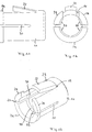
- Figs. 8, 9 and 10 each show a top view, an axial section and a perspective view of the magnet arrangement 35.
- the magnet arrangement 35 is of hollow-cylindrical design and has an internal diameter which corresponds to the external diameter of the rod 2 or of the sections 5 and 6. The sections 5 and 6 and the rod 2 can thus slide within the magnet arrangement 35.
- the circumferential groove 36 can have for example a semicircular profile.
- Figs. 11, 12 and 13 show a side view, an end view and a perspective view of the elastic sleeve 11.
- the circumferential flange 37 on the internal circumferential face of the sleeve 11 also has a semicircular profile which fits the profile of the circumferential groove 36.
- Fig. 14 is a side view
- Fig. 15 is a sectional view along the line B-B in Fig. 14
- Fig. 16 is a side view
- Fig. 17 is a sectional view along the line C-C in Fig. 16.
- the axial groove 25 can be seen on the internal wall region of the through-opening 10.
- the axial groove 25 has oblique side walls 25a and 25b which extend in the longitudinal direction of the through-opening 10.
- the side walls 25a and 25b are at an angle to the base surface 25c of the axial groove 25 which is greater than 90 degrees.
- the junction area between the base surface 25c and the side walls 25a and 25b is also rounded.
- the elastic wall region 22 of the sleeve 11 is located within the axial groove 25 after the sleeve 11 is inserted into the through-opening 10, by turning the sleeve 11 within the through-opening 10 it is possible to cause the elastic wall region 22 to be moved out of the axial groove 25 by running up onto one of the side walls 25a or 25b (depending on the direction of rotation) and to be pressed in the direction of the central axis of the sleeve 11. If the sleeve 11 is further rotated sufficiently, the free end of the elastic wall region 22 thus disengages (designated in Fig.
- the collar 24 can be appropriately constructed to make rotating the sleeve 11 within the through-opening 10 easier so that for example pliers or an open-jawed spanner can be applied there.
- the entire rod antenna 1 can thus be easily replaced if it has been damaged for whatever reasons. A special tool is not required for this.
- the collar 24 can, under certain circumstances, also be provided with a knurl so that the sleeve 11 can be rotated manually.
- Figs. 18 and 19 show a third exemplary embodiment of the present invention. Components identical to those in Figs. 6 to 17 are provided here with the same reference symbols and are not described again.
- the sleeve 11 is not of elastic construction here but rather the magnet arrangement 35 and sleeve 11 are permanently connected to one another, for example bonded.
- the sleeve 11 has on its outer circumferential face a thread 38 so that it can be screwed into a corresponding internal thread which is located in the through-opening 10.
- the collar 24 of the sleeve 11 has a knurl here in order to facilitate the screwing-in and screwing-out process of the sleeve 11.
- an elastic spring contact 39 is attached to the circuit board and the housing in order to make an electrical connection between the magnet arrangement 35 and the transmitting and receiving circuit.
- the spring contact 39 acts on that end of the electrically conductive magnet arrangement 35 which projects beyond the sleeve 11 on the housing side.
- the electrical tap in the exemplary embodiment is also configured according to Figs. 6 and 7.
- the magnet arrangement 35 which is electrically conductive, of course also projects beyond the sleeve 11 viewed in the direction of the interior of the housing 8.
- FIG. 20 A fourth exemplary embodiment of the invention is shown in Fig. 20. This is a modification of the third exemplary embodiment with the effect that the region, acted on by the spring contact 39, of the magnet arrangement 35 is now of cylindrical construction and not conical as was the case in the exemplary embodiment according to Figs. 18 and 19.
Landscapes
- Support Of Aerials (AREA)
- Structure Of Receivers (AREA)
- Liquid Developers In Electrophotography (AREA)
- Input Circuits Of Receivers And Coupling Of Receivers And Audio Equipment (AREA)
- Details Of Aerials (AREA)
Priority Applications (4)
| Application Number | Priority Date | Filing Date | Title |
|---|---|---|---|
| EP95117608A EP0773632B1 (fr) | 1995-11-08 | 1995-11-08 | Radio émetteur-récepteur |
| DE69532502T DE69532502T2 (de) | 1995-11-08 | 1995-11-08 | Funksendeempfänger |
| AT95117608T ATE258731T1 (de) | 1995-11-08 | 1995-11-08 | Funksendeempfänger |
| US08/745,042 US5880696A (en) | 1995-11-08 | 1996-11-07 | Retractable antenna for a radio transmitting and receiving device |
Applications Claiming Priority (1)
| Application Number | Priority Date | Filing Date | Title |
|---|---|---|---|
| EP95117608A EP0773632B1 (fr) | 1995-11-08 | 1995-11-08 | Radio émetteur-récepteur |
Publications (2)
| Publication Number | Publication Date |
|---|---|
| EP0773632A1 true EP0773632A1 (fr) | 1997-05-14 |
| EP0773632B1 EP0773632B1 (fr) | 2004-01-28 |
Family
ID=8219794
Family Applications (1)
| Application Number | Title | Priority Date | Filing Date |
|---|---|---|---|
| EP95117608A Expired - Lifetime EP0773632B1 (fr) | 1995-11-08 | 1995-11-08 | Radio émetteur-récepteur |
Country Status (4)
| Country | Link |
|---|---|
| US (1) | US5880696A (fr) |
| EP (1) | EP0773632B1 (fr) |
| AT (1) | ATE258731T1 (fr) |
| DE (1) | DE69532502T2 (fr) |
Cited By (2)
| Publication number | Priority date | Publication date | Assignee | Title |
|---|---|---|---|---|
| EP0948080A1 (fr) * | 1998-03-31 | 1999-10-06 | Koninklijke Philips Electronics N.V. | Appareil électronique portable muni d'une antenne |
| EP0993126A3 (fr) * | 1998-10-06 | 2001-03-14 | Matsushita Electric Industrial Co., Ltd. | Dispositif et procédé pour la fixation d'une antenne |
Families Citing this family (20)
| Publication number | Priority date | Publication date | Assignee | Title |
|---|---|---|---|---|
| JP2001509338A (ja) * | 1997-01-29 | 2001-07-10 | チャング,エウング−ソーン | 無線機器用アンテナ |
| USD413604S (en) | 1997-02-28 | 1999-09-07 | Telefonaktiebolaget Lm Ericsson | Aerial |
| US6336036B1 (en) * | 1998-07-08 | 2002-01-01 | Ericsson Inc. | Retractable dual-band tapped helical radiotelephone antennas |
| JP2000059118A (ja) * | 1998-08-07 | 2000-02-25 | Tokin Corp | 伸縮式ホイップアンテナ |
| US6766037B1 (en) | 1998-10-02 | 2004-07-20 | Canon Kabushiki Kaisha | Segmenting moving objects and determining their motion |
| US6133885A (en) * | 1998-11-03 | 2000-10-17 | Motorola, Inc. | Non-telescoping antenna assembly for a wireless communication device |
| AU139333S (en) * | 1998-11-26 | 1999-12-15 | Ericsson Telefon Ab L M | A mobile telephone |
| AU139339S (en) * | 1998-11-26 | 1999-12-15 | Ericsson Telefon Ab L M | An extendible antenna |
| US6166696A (en) * | 1998-11-30 | 2000-12-26 | T&M Antennas | Dual radiator galvanic contact antenna for portable communicator |
| FR2793368B1 (fr) * | 1999-05-03 | 2001-07-13 | Cit Alcatel | Telephone muni d'une antenne connectee |
| US6215446B1 (en) | 1999-07-23 | 2001-04-10 | Centurion Wireless Technologies, Inc. | Snap-in antenna |
| US6219007B1 (en) | 1999-08-23 | 2001-04-17 | The Whitaker Corporation | Antenna assembly |
| SE0002712D0 (sv) * | 1999-11-19 | 2000-07-19 | Allgon Ab | An antenna device and a communication device comprising such an antenna device |
| US7620435B2 (en) * | 2000-12-22 | 2009-11-17 | Intel Corporation | Communication module with retractable antennae and method therefor |
| CA2413360C (fr) * | 2002-11-29 | 2008-09-16 | Research In Motion Limited | Combinaison d'un tube et d'une pince pour la mise a la masse d'une antenne sans fil |
| US7113149B2 (en) * | 2003-09-25 | 2006-09-26 | Radio Frequency Systems, Inc. | Apparatus and method for clamping cables in an antenna |
| US8063848B2 (en) * | 2008-12-02 | 2011-11-22 | Bae Systems Information And Electronic Systems Integration Inc. | X, Ku, K band omni-directional antenna with dielectric loading |
| TWI449259B (zh) * | 2011-02-22 | 2014-08-11 | Wistron Neweb Corp | 用來調整天線模組角度之螺桿機構及其天線系統 |
| EP2944982A1 (fr) * | 2014-05-12 | 2015-11-18 | Ampass-explorer Corp. | Antenne émettrice et réceptrice pour un instrument de polarisation d'antenne de recherche |
| CN112821023A (zh) * | 2021-01-11 | 2021-05-18 | 深圳市道通科技股份有限公司 | 一种汽车通信接口设备 |
Citations (3)
| Publication number | Priority date | Publication date | Assignee | Title |
|---|---|---|---|---|
| JPH01261004A (ja) * | 1988-04-12 | 1989-10-18 | Matsushita Electric Ind Co Ltd | アンテナ切替え装置 |
| US5168278A (en) * | 1991-03-19 | 1992-12-01 | Sanyo Electric Co., Ltd. | Antenna device for electronic devices |
| WO1994006319A1 (fr) * | 1992-09-11 | 1994-03-31 | Randolph-Rand Corporation | Dispositif de verrouillage magnetique |
Family Cites Families (10)
| Publication number | Priority date | Publication date | Assignee | Title |
|---|---|---|---|---|
| FR1588021A (fr) * | 1968-10-23 | 1970-04-03 | ||
| FI79210C (fi) * | 1988-04-18 | 1989-11-10 | Nokia Mobile Phones Ltd | Foergreningsnaet i kedja foer en basstation i ett radiotelefonnaet. |
| FI84537C (fi) * | 1990-01-18 | 1991-12-10 | Nokia Mobile Phones Ltd | Diversitetsantennkoppling foer en digital mobiltelefon. |
| JP2554762B2 (ja) * | 1990-02-23 | 1996-11-13 | 株式会社東芝 | アンテナと無線機 |
| FI89646C (fi) * | 1991-03-25 | 1993-10-25 | Nokia Mobile Phones Ltd | Antennstav och foerfarande foer dess framstaellning |
| JP2703670B2 (ja) * | 1991-04-12 | 1998-01-26 | 三菱電機株式会社 | アンテナ装置 |
| US5343213A (en) * | 1991-10-22 | 1994-08-30 | Motorola, Inc. | Snap-in antenna assembly |
| FI92446C (fi) * | 1992-12-22 | 1994-11-10 | Nokia Mobile Phones Ltd | Autoradiopuhelinantenni |
| US5469177A (en) * | 1993-09-15 | 1995-11-21 | Motorola, Inc. | Antenna assembly and method therefor |
| SE505119C2 (sv) * | 1995-10-25 | 1997-06-30 | Allgon Ab | Antennlåsningsanordning |
-
1995
- 1995-11-08 DE DE69532502T patent/DE69532502T2/de not_active Expired - Fee Related
- 1995-11-08 EP EP95117608A patent/EP0773632B1/fr not_active Expired - Lifetime
- 1995-11-08 AT AT95117608T patent/ATE258731T1/de not_active IP Right Cessation
-
1996
- 1996-11-07 US US08/745,042 patent/US5880696A/en not_active Expired - Lifetime
Patent Citations (3)
| Publication number | Priority date | Publication date | Assignee | Title |
|---|---|---|---|---|
| JPH01261004A (ja) * | 1988-04-12 | 1989-10-18 | Matsushita Electric Ind Co Ltd | アンテナ切替え装置 |
| US5168278A (en) * | 1991-03-19 | 1992-12-01 | Sanyo Electric Co., Ltd. | Antenna device for electronic devices |
| WO1994006319A1 (fr) * | 1992-09-11 | 1994-03-31 | Randolph-Rand Corporation | Dispositif de verrouillage magnetique |
Non-Patent Citations (1)
| Title |
|---|
| PATENT ABSTRACTS OF JAPAN vol. 14, no. 18 (E - 873) 16 January 1990 (1990-01-16) * |
Cited By (3)
| Publication number | Priority date | Publication date | Assignee | Title |
|---|---|---|---|---|
| EP0948080A1 (fr) * | 1998-03-31 | 1999-10-06 | Koninklijke Philips Electronics N.V. | Appareil électronique portable muni d'une antenne |
| US6107971A (en) * | 1998-03-31 | 2000-08-22 | U.S. Philips Corporation | Portable electronic device with an antenna |
| EP0993126A3 (fr) * | 1998-10-06 | 2001-03-14 | Matsushita Electric Industrial Co., Ltd. | Dispositif et procédé pour la fixation d'une antenne |
Also Published As
| Publication number | Publication date |
|---|---|
| DE69532502T2 (de) | 2004-11-04 |
| US5880696A (en) | 1999-03-09 |
| ATE258731T1 (de) | 2004-02-15 |
| EP0773632B1 (fr) | 2004-01-28 |
| DE69532502D1 (de) | 2004-03-04 |
Similar Documents
| Publication | Publication Date | Title |
|---|---|---|
| US5880696A (en) | Retractable antenna for a radio transmitting and receiving device | |
| US5856806A (en) | Antenna support sleeve with fingerlock | |
| TWI450457B (zh) | 同軸線纜連接器及其組裝方法 | |
| US7186068B2 (en) | Fixing element | |
| US7394434B2 (en) | Combination of tube assembly and clip for wireless antenna grounding | |
| SE505119C2 (sv) | Antennlåsningsanordning | |
| KR100206074B1 (ko) | 나사 단자를 갖는 전기 장치 | |
| US6369764B1 (en) | Extendible whip antenna assembly with a whip antenna having a notched stopper | |
| US2293719A (en) | Binding post | |
| EP1914762B1 (fr) | Embout d'un composant inductif et composant inductif | |
| US5890923A (en) | Connector alignment guide | |
| EP1794839B1 (fr) | Connecteur de raccordement d'une antenne | |
| US6493929B2 (en) | Guide tool for coupling an end connector to a coaxial cable | |
| EP1598899B1 (fr) | Antenne pour un terminal mobile | |
| US20130210293A1 (en) | Clamp body for terminal | |
| US4062636A (en) | Elongate cylindrical members securement | |
| US4518939A (en) | Solenoid with retainer stop | |
| US4755822A (en) | Antenna mounting | |
| EP1553656A1 (fr) | Dispositif de terminaison | |
| US6940472B2 (en) | Universal antenna adapter | |
| US4588876A (en) | Arrangement for the support of a program plate | |
| US5757336A (en) | Antenna unit | |
| EP1689024A1 (fr) | Dispositif de mise à la masse d'antenne pour un téléphone portable | |
| JPS5926705Y2 (ja) | 電源供給器 | |
| JPS5818222Y2 (ja) | 同軸ケ−ブル用プラグ |
Legal Events
| Date | Code | Title | Description |
|---|---|---|---|
| PUAI | Public reference made under article 153(3) epc to a published international application that has entered the european phase |
Free format text: ORIGINAL CODE: 0009012 |
|
| AK | Designated contracting states |
Kind code of ref document: A1 Designated state(s): AT DE FR GB IT NL SE |
|
| 17P | Request for examination filed |
Effective date: 19970619 |
|
| RAP1 | Party data changed (applicant data changed or rights of an application transferred) |
Owner name: NOKIA CORPORATION |
|
| 17Q | First examination report despatched |
Effective date: 20020418 |
|
| GRAH | Despatch of communication of intention to grant a patent |
Free format text: ORIGINAL CODE: EPIDOS IGRA |
|
| GRAS | Grant fee paid |
Free format text: ORIGINAL CODE: EPIDOSNIGR3 |
|
| GRAA | (expected) grant |
Free format text: ORIGINAL CODE: 0009210 |
|
| AK | Designated contracting states |
Kind code of ref document: B1 Designated state(s): AT DE FR GB IT NL SE |
|
| PG25 | Lapsed in a contracting state [announced via postgrant information from national office to epo] |
Ref country code: NL Free format text: LAPSE BECAUSE OF FAILURE TO SUBMIT A TRANSLATION OF THE DESCRIPTION OR TO PAY THE FEE WITHIN THE PRESCRIBED TIME-LIMIT Effective date: 20040128 Ref country code: IT Free format text: LAPSE BECAUSE OF FAILURE TO SUBMIT A TRANSLATION OF THE DESCRIPTION OR TO PAY THE FEE WITHIN THE PRE;WARNING: LAPSES OF ITALIAN PATENTS WITH EFFECTIVE DATE BEFORE 2007 MAY HAVE OCCURRED AT ANY TIME BEFORE 2007. THE CORRECT EFFECTIVE DATE MAY BE DIFFERENT FROM THE ONE RECORDED.SCRIBED TIME-LIMIT Effective date: 20040128 Ref country code: AT Free format text: LAPSE BECAUSE OF FAILURE TO SUBMIT A TRANSLATION OF THE DESCRIPTION OR TO PAY THE FEE WITHIN THE PRESCRIBED TIME-LIMIT Effective date: 20040128 |
|
| REG | Reference to a national code |
Ref country code: GB Ref legal event code: FG4D |
|
| REF | Corresponds to: |
Ref document number: 69532502 Country of ref document: DE Date of ref document: 20040304 Kind code of ref document: P |
|
| PG25 | Lapsed in a contracting state [announced via postgrant information from national office to epo] |
Ref country code: SE Free format text: LAPSE BECAUSE OF FAILURE TO SUBMIT A TRANSLATION OF THE DESCRIPTION OR TO PAY THE FEE WITHIN THE PRESCRIBED TIME-LIMIT Effective date: 20040428 |
|
| NLV1 | Nl: lapsed or annulled due to failure to fulfill the requirements of art. 29p and 29m of the patents act | ||
| ET | Fr: translation filed | ||
| PG25 | Lapsed in a contracting state [announced via postgrant information from national office to epo] |
Ref country code: GB Free format text: LAPSE BECAUSE OF NON-PAYMENT OF DUE FEES Effective date: 20041108 |
|
| PLBE | No opposition filed within time limit |
Free format text: ORIGINAL CODE: 0009261 |
|
| STAA | Information on the status of an ep patent application or granted ep patent |
Free format text: STATUS: NO OPPOSITION FILED WITHIN TIME LIMIT |
|
| 26N | No opposition filed |
Effective date: 20041029 |
|
| PG25 | Lapsed in a contracting state [announced via postgrant information from national office to epo] |
Ref country code: DE Free format text: LAPSE BECAUSE OF NON-PAYMENT OF DUE FEES Effective date: 20050601 |
|
| GBPC | Gb: european patent ceased through non-payment of renewal fee |
Effective date: 20041108 |
|
| PG25 | Lapsed in a contracting state [announced via postgrant information from national office to epo] |
Ref country code: FR Free format text: LAPSE BECAUSE OF NON-PAYMENT OF DUE FEES Effective date: 20050729 |
|
| REG | Reference to a national code |
Ref country code: FR Ref legal event code: ST |