EP0773652A2 - Weglenkung von Nachrichtenpaketen in einem Mehrknotennetz - Google Patents
Weglenkung von Nachrichtenpaketen in einem Mehrknotennetz Download PDFInfo
- Publication number
- EP0773652A2 EP0773652A2 EP96307871A EP96307871A EP0773652A2 EP 0773652 A2 EP0773652 A2 EP 0773652A2 EP 96307871 A EP96307871 A EP 96307871A EP 96307871 A EP96307871 A EP 96307871A EP 0773652 A2 EP0773652 A2 EP 0773652A2
- Authority
- EP
- European Patent Office
- Prior art keywords
- node
- message
- group
- gateway
- nodes
- Prior art date
- Legal status (The legal status is an assumption and is not a legal conclusion. Google has not performed a legal analysis and makes no representation as to the accuracy of the status listed.)
- Withdrawn
Links
- 238000004891 communication Methods 0.000 claims abstract description 32
- 238000000034 method Methods 0.000 claims description 20
- 230000003044 adaptive effect Effects 0.000 abstract description 6
- 239000000872 buffer Substances 0.000 description 2
- 230000005540 biological transmission Effects 0.000 description 1
- 230000007423 decrease Effects 0.000 description 1
- 230000003247 decreasing effect Effects 0.000 description 1
- 230000001934 delay Effects 0.000 description 1
- 230000006870 function Effects 0.000 description 1
- 239000012464 large buffer Substances 0.000 description 1
- 238000012986 modification Methods 0.000 description 1
- 230000004048 modification Effects 0.000 description 1
- 238000012545 processing Methods 0.000 description 1
- 239000004065 semiconductor Substances 0.000 description 1
- 238000000926 separation method Methods 0.000 description 1
- 238000012546 transfer Methods 0.000 description 1
Images


Classifications
-
- H—ELECTRICITY
- H04—ELECTRIC COMMUNICATION TECHNIQUE
- H04W—WIRELESS COMMUNICATION NETWORKS
- H04W40/00—Communication routing or communication path finding
- H04W40/02—Communication route or path selection, e.g. power-based or shortest path routing
-
- H—ELECTRICITY
- H04—ELECTRIC COMMUNICATION TECHNIQUE
- H04Q—SELECTING
- H04Q3/00—Selecting arrangements
- H04Q3/64—Distributing or queueing
- H04Q3/66—Traffic distributors
- H04Q3/665—Circuit arrangements therefor
-
- H—ELECTRICITY
- H04—ELECTRIC COMMUNICATION TECHNIQUE
- H04L—TRANSMISSION OF DIGITAL INFORMATION, e.g. TELEGRAPHIC COMMUNICATION
- H04L45/00—Routing or path finding of packets in data switching networks
- H04L45/02—Topology update or discovery
- H04L45/04—Interdomain routing, e.g. hierarchical routing
-
- H—ELECTRICITY
- H04—ELECTRIC COMMUNICATION TECHNIQUE
- H04L—TRANSMISSION OF DIGITAL INFORMATION, e.g. TELEGRAPHIC COMMUNICATION
- H04L45/00—Routing or path finding of packets in data switching networks
- H04L45/18—Loop-free operations
-
- H—ELECTRICITY
- H04—ELECTRIC COMMUNICATION TECHNIQUE
- H04L—TRANSMISSION OF DIGITAL INFORMATION, e.g. TELEGRAPHIC COMMUNICATION
- H04L45/00—Routing or path finding of packets in data switching networks
- H04L45/20—Hop count for routing purposes, e.g. TTL
-
- H—ELECTRICITY
- H04—ELECTRIC COMMUNICATION TECHNIQUE
- H04L—TRANSMISSION OF DIGITAL INFORMATION, e.g. TELEGRAPHIC COMMUNICATION
- H04L45/00—Routing or path finding of packets in data switching networks
- H04L45/40—Wormhole routing
-
- H—ELECTRICITY
- H04—ELECTRIC COMMUNICATION TECHNIQUE
- H04W—WIRELESS COMMUNICATION NETWORKS
- H04W40/00—Communication routing or communication path finding
- H04W40/24—Connectivity information management, e.g. connectivity discovery or connectivity update
-
- H—ELECTRICITY
- H04—ELECTRIC COMMUNICATION TECHNIQUE
- H04W—WIRELESS COMMUNICATION NETWORKS
- H04W84/00—Network topologies
- H04W84/02—Hierarchically pre-organised networks, e.g. paging networks, cellular networks, WLAN [Wireless Local Area Network] or WLL [Wireless Local Loop]
- H04W84/04—Large scale networks; Deep hierarchical networks
Definitions
- the present invention relates generally to delivering messages in communication or multiprocessor networks (generally referred to as networks). More particularly, the present invention relates to an adaptive and dynamic message routing system for delivering messages in networks using multiple level routing tables at each node of the network.
- Communication networks that are generally used to interconnect computers or those used in telecommunication often comprise a number of nodes and communication links (links, routes) as shown in Fig. 1.
- Each node generally comprises a processor, one or more storage units and several I/O ports for connecting that node to the other nodes in the network.
- node N1 may communicate to node N2 over communication link N1-N2
- node N3 may communicate to node N5 over communication link N3-N5.
- Each node in the network is generally capable of acting as a source, sink, and an intermediate node.
- Source node is a node where the message to be communicated is generated and transmitted from; sink (destination) node is a node where the message generated by the source is to be communicated to (delivered to); and an intermediate node is a node between a source and a destination node encountered by the message in its route to the destination node.
- each message sent over the network generally comprises a message header and the information to be transmitted.
- the message header generally includes the address of the destination node where the message is supposed to be delivered and the address of the source node where the message was generated from.
- the network is generally utilized to deliver electronic messages among various nodes in the network.
- a majority of multinode communication networks have been arranged as either a "connection type” network, a “connectionless type” network or as a "wormhole” network.
- connection type network In a connection type network, all of the data transfer takes place via a communication path which is completely established from a source node to a destination node by a message header before the message is transferred.
- the communication path established between the source node and destination node, including all the intermediate nodes and links, is held up and not released until the message has been completely delivered.
- connectionless type network In a connectionless type network ("store and forward" network), a message is transferred from a source node to a destination node via packets (packets or datagrams refer to a message to be transmitted) where the packets are stored at each intermediate node until a connection is made to the next node (either intermediate or destination node) at which time the data is then transferred to that next node.
- Connectionless type networks require large buffer (memory) space at each node for storing and forwarding messages from one node to the next node in the network.
- wormhole networks In wormhole networks, a message is transmitted from a source node to a destination node immediately after the message header has been transmitted thus avoiding storing and forwarding of the message at each intermediate node. By not storing and forwarding the message at each node, wormhole routing avoids using large memory buffers, and the delays associated with using these memory buffers, at each node of the network. This results in tremendous memory savings in the network as a whole.
- wormhole routing techniques have relied on the network topology to route messages and to avoid deadlocks and bottlenecks.
- E-cube routing routes messages in the order of dimensions in a hypercube network.
- Address-delta routing techniques route messages in X and then Y directions based on the difference between the address of the source and destination in a mesh network.
- these routing techniques rely directly on the network topology and therefore, are not transferable from one network topology to another or vice versa.
- network topologies have imposed limits on the exact number of nodes in a network.
- hypercube networks limit the number of nodes in the network to a power of 2 and a mesh network cannot support any prime number of nodes.
- efficient message delivery and avoiding bottlenecks and preventing messages from endless travelling becomes an ever growing concern.
- a message delivery and routing method and apparatus that is independent of a network topology (i.e., an adaptive method and apparatus); wherein the routing decisions are distributed among the nodes of the network (i.e., dynamic routing); and which at the same time can deliver messages in the shortest possible time using the minimum amount of network resources.
- a level-1 table at each node n comprises multiple entries, one entry for each group in the network excluding the group that node n belongs to.
- Each entry provides multiple message delivery directions, including the most-preferred message delivery direction, for routing a given message from node n of a group to other groups in the network. Therefore, each node has a level-1 table with entries unique to that node. The message delivery directions in each entry are further ordered by the relative distance between the group identified by that entry and node n.
- a level-2 table at each node n comprises multiple entries, each entry provides multiple message delivery directions, including the most-preferred message delivery direction, for routing a message from node n of group Gi to only other local nodes in group Gi. Therefore, each node n has a level-2 table with entries that are unique to that node. The message delivery directions in each entry are further ordered by the relative distance between the local node identified by that entry and node n.
- entries in the level-1 table provide means for communicating messages from a node of a group to another group adaptively and dynamically and the entries in the level-2 table allows the message delivered to the group to be routed to a specific local node within that group adaptively and dynamically.
- a level-1 table at each gateway node Gn comprises multiple entries, one entry for every other gateway node in the network.
- Each entry provides multiple message delivery directions, including the most-preferred message delivery direction, for routing a given message from gateway node Gn to one other gateway node in the network.
- the entries are unique in each level-1 table.
- the message delivery directions in each entry are further ordered by the relative distance between the gateway identified by that entry and gateway node Gn.
- a level-2 table at each local node n controlled by gateway node Gn comprises multiple entries, each entry provides multiple message delivery directions, including the most-preferred message delivery direction, for routing a message from node n to other local nodes controlled by gateway node Gn.
- the entries are unique in each level-2 table.
- the message delivery directions in each entry are further ordered by the relative distance between the local node identified by that entry and node n.
- a deflection counter is also added to each message header where each time the message is routed from one node to another node or from one gateway to another gateway not using the most-preferred message delivery direction (the message is said to be deflected under such circumstances), the deflection counter is decremented by one count. If the deflection counter reaches zero and the message has not yet been delivered to its destination, the message delivery is terminated, the links acquired are released and the source is informed that the message could not be delivered. The message not delivered is referred to as "unsuccessfully terminated" or "unsuccessfully delivered” message.
- Use of a deflection counter in message headers prevents messages from endless travelling in the network without getting delivered to the destinations at all or in a predetermined number of deflections.
- the message delivery is retried for transmission from the source to the destination.
- a backup and retry policy is implemented to guide the retry process.
- the exponential backup and retry process may be initiated by the processor controlling the source node as many times as necessary until the message is delivered to the destination node or a predetermined backup and retry limit is reached.
- the multiple routing tables used at each node supports any network topology having any number of nodes thus avoiding the problem associated with fixed network topology. It further allows for efficient delivery of messages using two level addressing capability.
- the routing system and method according to the present invention is adaptive because table entries can be changed if a node is added to or deleted from the network or if the node should be bypassed because of link failure.
- the routing system and method according to the present invention is also dynamic because delivery directions are controlled by each node in a path where several routes for delivering messages are provided at each node and any one of them can be utilized for delivering messages depending upon local conditions such as link availability.
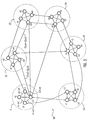
- a depiction of a multinode network 50 according to the preferred embodiment of the present invention.
- the nodes in the network are divided into a plurality of groups, each group comprising at least one node referred to as a local node.
- the selection criteria for determining which local node should be assigned to which group may be made, for example, based on physical distance proximity among the nodes.
- symbols G1, G2, G3, ..., and G6, signify group 1, group 2, group 3, ..., and group 6, respectively.
- Each group is also shown to comprise, for illustration purposes only, four local nodes identified by symbols n1, n2, n3 and n4. Each group may have a different number of local nodes.
- Fig. 2 further illustrates several links connecting one or more local nodes in each group to one or more local nodes of other groups.
- group 1 is connected to group 2 via two links, one between node 4 of group 1 and node 1 of group 2 identified as G1.n4-G2.n1 and one link between node 3 of group 1 and node 3 of group 2 identified as G1.n3-G2.n3.
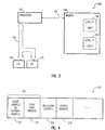
- Node 100 comprises a processor 110 in communication with memory (storage medium) 120 via link 115.
- Memory 120 which is preferably a semiconductor memory (DRAM, SRAM, NVRAM or alike) further comprises a level-1 table 130 and level-2 table 140.
- Level-1 table 130 comprises entries providing communication directions from node 100 to other groups in the network.
- Level-2 table 140 comprises entries providing message delivery directions among the local nodes of a group of which node 100 is one of the local nodes.
- Processor 110 is further connected to I/O channels 160 and 170 (two I/O channels are shown for illustration purposes only) via communication channel 150. I/O channels 160 and 170 provide means for communication between node 100 and predetermined nodes in network 50.
- Message header 200 which is typically several bytes long, comprises a destination address field 210, a deflection counter field 220, and a source address field 230.
- Destination address 210 further comprises a group (gateway) address field 212 and a local node address field 214.
- Group address 212 may be a byte or more long and a local node address 214 may be a byte or more long.
- group address 212 is used to route a message from a node of a source group (source group comprises the source node) to a destination group (destination group comprises the destination node).
- the local node address 214 is then used to route the message to the destination node.
- Each message routed in the network has a message header associated with it for, among other things, identifying the source node from which the message was sent from and the destination node to which the message should be delivered to.
- processor 110 of node 100 when processor 110 of node 100 receives a message header from another node in network 50, it first compares the group address 212 of the message header with node 100 group address. If they match each other (are equal), the message is delivered to node 100 for further processing in accordance with the content of local node address 214 and level-2 table 140. If group address 212 of the message header is not the same as (does not match) node 100 group address, then group address 212 is used as an index into level-1 table 130 to obtain possible message delivery directions along which the message may be forwarded toward its destination node from node 100.
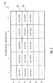
- FIG. 5 there is shown a depiction of a level-1 table 300 stored at memory locations of the nodes of group 1 (G1) in network 50 according to the present invention. Similar tables having different entries are also stored at nodes of the other groups in the network.
- Each row of table 300 stores an entry which is associated with a group in the network. Each entry comprises several sub-entries. The sub-entries in each row (five in this example for illustration purposes only) provide message delivery directions to the group associated with that row. For example, in table 300, row 320 is associated with group 2 (G2) and row 330 is associated with group 3 (G3).
- the sub-entries in row 320 provide message delivery directions for delivering messages from group 1 to group 2 and sub-entries in row 330 provide delivery directions for delivering messages from group 1 to group 3, respectively.
- the sub-entries in each row are further ordered from left to right from the most preferred message delivery route (direction) to the least preferred message delivery route from the current group to the group associated with that row.
- sub-entries in column 1 are the most preferred route for delivering messages from group 1 to other groups in the network
- sub-entries in column 2 are the second most preferred routes for delivering messages from group 1 to other groups in the network
- sub-entries in column 5 are the least preferred message delivery routes for delivering messages from group 1 to other groups in the network.
- the shortest message delivery path is defined as G1.n4-G2.n1 (row 320 and column 1) which means there is a direct communication link between node 4 of group 1 and node 1 of group 2. If the link G1.n4-G2.n1 is busy or down due to failure, then the next sub-entry in row 320 (G1.n3-G2.n3) is selected as the path (route) to deliver the message from group 1 to group 2.
- FIG. 6 there is shown a depiction of a level-2 table 400 of local node n1 of group G1 in network 50. Similar tables having different entries are also stored at the nodes of group G1 and the nodes of the other groups in the network.
- Each row of table 400 stores an entry which is associated with a local node of group G1.
- Each entry comprises several sub-entries. For example, row 420 is associated with local node 2 (n2) of G1 and row 430 is associated with local node 3 (n3) of G1.
- the sub-entries in each row (three in this example for illustration purposes only) provide delivery directions to the local node associated with that row.
- So sub-entries in row 420 of table 400 reflect the message delivery directions available for delivering messages from local node 1 to local node 2 of the group G1.
- the sub-entries in each row are further ordered from the most preferred delivering route to the least preferred delivering route from the current local node to the local node associated with that row.
- So sub-entries in column 1 are defined as the most preferred delivery routes from node 1 to local node 2, 3 and 4 of the group G1.
- Sub-entries in column 2 are defined as the second most preferred delivery route from n1 to other local nodes in the group G1.
- the most preferred message delivery route is defined as n1-n2 which means there is a direct communication link between node 1 and node 2. If the link n1-n2 is unavailable, then the next sub-entry in row 420 is selected (n1-n3) as the path to deliver the message from node 1 to node 2. As stated earlier, the deflection counter in the message header is decremented by one every time the most-preferred message delivery route is unavailable for transmitting a message.
- processor 110 compares the content of destination group address 212 in message header 210 with node 100 group address (block 510). If the content of destination group address 212 is the same as node 100 group address, processor 110 then compares the content of destination local node address 214 with node 100 local node address. (block 520). If they match each other (are the same), then the message has been received at its destination and routing is complete and message delivery has been successfully completed as shown by block 530.
- processor 110 selects message delivery directions from level-1 table 130 using the content of destination group address 212 (block 550) as an index to select an entry in level-1 table 130.
- the message delivery route selected from level-1 table 130 by processor 110 is then used to route the message to the next node where the next node could either be the destination node or another intermediate node (block 570).
- Processor 110 then checks to see whether the most preferred message delivery route (routes in column 1 of Fig. 5) selected from an entry in level-1 table 130 is available for message delivery (block 580). If the most preferred route is available, then the message is sent to the next node using that most preferred route (block 590).
- deflection counter 220 in message header 200 is first decremented by one count (block 600).
- Processor 110 selects the next alternate route that is listed in the routing table (block 610) and determines whether the selected route is available (block 620). If the selected route is available (block 630) the message is sent to the next node in the network (block 590). If none of the routes in the selected entry from level-1 table are available, then the message delivery operation is stopped, all the acquired links up to node 100 from the source node are released and a message is sent back to the source node stating that the message could not be delivered.
- processor 110 selects a message delivery direction from level-2 table 140 of node 100 using the content of destination local node address 214 as an index (block 560). The message is then routed to the next local node in the same group as node 100 based on the entry selected from the level-2 routing table (block 570). Again, if the most preferred route in the entry selected from level-2 table 140 by processor 110 is available, the message is delivered to the next local node using that route (block 590). If the most preferred route is not available, deflection counter 220 in the message header is decremented and further attempts are made to select alternate routes from the selected entry for delivering messages as shown by blocks 600, 610, 620 and 630.
- a depiction of a multinode network 650 according to an alternative embodiment of the present invention.
- the nodes in network 650 are divided into two sets designated as gateway nodes and local nodes.
- Each gateway node controls message delivery to a plurality of local nodes that are assigned to that gateway node.
- the selection criterion for determining which local nodes should be assigned to which gateway node is based on physical distance proximity among the nodes although other criteria may also be employed.
- nodes G1, G2, G3, ..., and G6 are designated as gateway nodes.
- four local nodes are shown to be assigned to each gateway node.
- Local nodes assigned to each gateway node are labelled as n1, n2, n3 and n4.
- local nodes are identified by a designation comprising a reference to the gateway node and the associated local node.
- local node n1 associated with gateway 1 is identified as G1.n1
- local node n3 associated with gateway 5 is identified as G5.n3.
- Gateway nodes are linked together via one or more communication links.
- gateway node G1 is linked to G2, G3 and G4 via links G1-G2, G1-G3, and G1-G4, respectively
- gateway node G2 is linked to G1, G3, and G5 via communication links G1-G2, G2-G3, and G2-G5, respectively.
- Local nodes associated with each gateway node are also linked together via one or more communication links.
- gateway node 700 comprises a processor 710 in communication with memory 720 through link 715.
- Memory 720 further stores a level-1 table 730.
- Level-1 table 730 comprises entries providing message delivery directions from gateway node 700 to other gateway nodes in network 650.
- Processor 710 is further connected to several I/O channels through communication link 750.
- I/O channels 760, 765, 770, and 775 are shown for illustrative purposes.
- I/O channels 760 and 765 provide communication links to two other gateway nodes (not shown) in network 650 via links 761 and 766, respectively.
- I/O channels 770 and 775 provide communication links to local nodes 792 and 796 via links 771 and 776, respectively.
- processor 710 receives a message header 200 from another gateway node in the network through one of the I/O channels (760 or 765). Once processor 710 receives the message header, it compares destination gateway address 212 of message header 200 with the address of gateway node 700. If they are the same, the message is delivered to gateway node 700 and from there is directed to local nodes 790 for further delivery to one of the local nodes using the level-2 routing table stored at each local node. If the two addresses are not the same, the gateway address 212 is used as an index into level-1 routing table 730 to obtain message delivery directions along which the message may be forwarded from current gateway node 700 to its destination.
- FIG. 10 there is shown a depiction of a level-1 table 800 associated with gateway node 1 shown in Fig. 8.
- a similar table with different entries is also stored at each other gateway node of network 650.
- Each row of table 800 stores an entry associated with a gateway node in network 650.
- Each entry in table 800 further comprises sub-entries.
- row 820 is associated with gateway node G2.
- the sub-entries in each row (four shown in this example) provide message delivery directions to the gateway node associated with that row.
- sub-entries in row 820 provide message delivery directions for delivering messages from gateway node G1 to gateway node G2 in network 650.
- the sub-entries in each row are further ordered, from left to right, based on a predetermined criterion defining the most preferred routes for delivering a message from gateway node G1 to the gateway node associated with that row. So, for example, message delivery directions identified by row 820 and column 1 are the most preferred route for delivering messages from gateway node G1 to gateway node G2 in network 650. In general, sub-entries in column 1 are the most preferred message delivery routes from G1 to other gateway nodes in network 650. Sub-entries in column 2 are the second most preferred routes for delivering messages from gateway node G1 to other gateways in network 650.
- the most preferred message delivery path is defined as G1-G2 which provides a direct communication link between gateway node G1 and gateway node G2. If the direct communication link G1-G2 is unavailable because it is busy or it is down due to failure, then the next sub-entry identified by row 820 and column 2 is selected as the path to deliver the message from gateway node G1 to gateway node G2, which is identified as G1-G3.
- gateway node G1 and gateway node G2 are unavailable, then the message is sent from gateway node G1 to gateway node G3 and then an attempt is made to deliver the message from G3 to G2, the final destination.
- the deflection counter in the message header is decremented by a count before an attempt is made to deliver the message through an alternative route. This will ensure that a message is not routed endlessly (i.e., travelling the network from one node to another without ever reaching the destination node) in network 650.
- FIG. 11 there is shown a depiction of a level-2 table 900 of local nodes n1, n2, n3, and n4 associated with gateway G1 of network 650 shown in Fig. 8.
- Each row of table 900 comprises an entry associated with one of the local nodes controlled by gateway node G1.
- Each entry in table 900 further comprises sub-entries.
- row 920 is associated with local node n2.
- the sub-entries in row 920 (three in this example) provide message delivery directions to the local node associated with that row.
- sub-entries in row 920 reflect the delivery directions available for delivering messages from local node n1 to local node n2.
- the sub-entries in each row are further ordered from left to right from the most preferred route to the least preferred route from the current local node to the local node associated with a given row. Therefore, the sub-entries in column 1 are defined as the most preferred delivery route from node 1 to any other local node in gateway node G1. Sub-entries in column 2 are defined as the second most preferred delivery route from node 1 to other local nodes in gateway node G1. For example, if a message is sent from node n1 to node n2, then according to the sub-entries in row 920, the most preferred message delivery route is defined as n1-n2 which provides a direct communication link between node n1 and node n2. If the link n1-n2 is unavailable for message delivery, then the next sub-entry in row 920 is selected (n1-n4) as the path to deliver the message from node n1 to node n2.
- Applicants' invention of using two routing tables at each node having the combined g+n entries provides an adaptive and dynamic routing scheme in a network having g*n nodes. This is in contrast with the prior art or conventional practice of having a single table at each node, each table comprising g*n entries to support g*n nodes.
- Applicants' invention of using two routing tables at each node results in tremendous storage saving at each network node and provides a more efficient method of routing messages among the nodes of a network by utilizing small tables as opposed to extremely large tables. This results in faster delivery of messages and more efficient utilization of a network resources.
- Applicants' invention allows the routing decisions for each message to be made at local nodes in the network, based on local condition, thus providing dynamic routing capability. This is in contrast with routing methods wherein a predefined routing table is stored in a message header of a message or a predefined routing table is stored at each node of a network. Furthermore, the size of the level-1 table and level-2 table used at network nodes may be increased or decreased as the number of nodes in the network increases or decreases, respectively, thus providing an adaptive routing system and method.
- each group or gateway node instead of using four local nodes associated with each group or gateway node, a smaller or larger number of local nodes may be utilized.
- the network instead of dividing the network nodes into local nodes and groups, each group comprising a predetermined number of local nodes, the network can be divided into three, four or even higher number of sets and by doing so, a higher number of tables may be utilized for delivering messages in the network.
- each node instead of each node having its own processor and memory unit, it is possible that a plurality of the nodes may simply share (have access to) a processor and a storage medium.
Landscapes
- Engineering & Computer Science (AREA)
- Computer Networks & Wireless Communication (AREA)
- Signal Processing (AREA)
- Data Exchanges In Wide-Area Networks (AREA)
- Small-Scale Networks (AREA)
- Multi Processors (AREA)
Applications Claiming Priority (2)
| Application Number | Priority Date | Filing Date | Title |
|---|---|---|---|
| US555539 | 1995-11-09 | ||
| US08/555,539 US5602839A (en) | 1995-11-09 | 1995-11-09 | Adaptive and dynamic message routing system for multinode wormhole networks |
Publications (2)
| Publication Number | Publication Date |
|---|---|
| EP0773652A2 true EP0773652A2 (de) | 1997-05-14 |
| EP0773652A3 EP0773652A3 (de) | 1998-02-04 |
Family
ID=24217654
Family Applications (1)
| Application Number | Title | Priority Date | Filing Date |
|---|---|---|---|
| EP96307871A Withdrawn EP0773652A3 (de) | 1995-11-09 | 1996-10-30 | Weglenkung von Nachrichtenpaketen in einem Mehrknotennetz |
Country Status (6)
| Country | Link |
|---|---|
| US (1) | US5602839A (de) |
| EP (1) | EP0773652A3 (de) |
| JP (1) | JPH09153892A (de) |
| KR (1) | KR100221381B1 (de) |
| CN (1) | CN1106733C (de) |
| MY (1) | MY112850A (de) |
Cited By (1)
| Publication number | Priority date | Publication date | Assignee | Title |
|---|---|---|---|---|
| GB2320159A (en) * | 1996-10-02 | 1998-06-10 | Ibm | Aggregate Inernet route switching |
Families Citing this family (71)
| Publication number | Priority date | Publication date | Assignee | Title |
|---|---|---|---|---|
| US5740346A (en) * | 1996-02-22 | 1998-04-14 | Fujitsu, Ltd. | System and method for dynamic network topology exploration |
| US5699522A (en) * | 1996-02-23 | 1997-12-16 | Unisys Corporation | Data processing system with fast message processing for upgraded input/output stations |
| SE9604491L (sv) * | 1996-12-05 | 1998-06-06 | Ericsson Telefon Ab L M | Anordning och förfarande i överföringssystem |
| JP3523019B2 (ja) | 1997-06-18 | 2004-04-26 | 富士通株式会社 | フレーム中継装置 |
| US6236642B1 (en) | 1997-07-17 | 2001-05-22 | Siemens Information And Communication Networks, Inc. | Apparatus and method for network resource preservation |
| US6091706A (en) | 1997-07-17 | 2000-07-18 | Siemens Information And Communication Networks, Inc. | Apparatus and method for preventing network rerouting |
| DE19835668A1 (de) | 1997-08-07 | 1999-02-25 | Matsushita Electric Industrial Co Ltd | Übertragungsmedienverbindungsvorrichtung, steuernde Vorrichtung, gesteuerte Vorrichtung und Speichermedium |
| US6247059B1 (en) | 1997-09-30 | 2001-06-12 | Compaq Computer Company | Transaction state broadcast method using a two-stage multicast in a multiple processor cluster |
| AU3186599A (en) * | 1998-04-03 | 1999-10-25 | Netcore Systems, Inc. | High speed combination router-switch |
| US6546429B1 (en) * | 1998-09-21 | 2003-04-08 | International Business Machines Corporation | Non-uniform memory access (NUMA) data processing system that holds and reissues requests at a target processing node in response to a retry |
| US6584073B1 (en) | 1999-06-02 | 2003-06-24 | Sun Microsystems, Inc. | Network topologies |
| US6791939B1 (en) | 1999-06-02 | 2004-09-14 | Sun Microsystems, Inc. | Dynamic generation of deadlock-free routings |
| US6603742B1 (en) | 1999-06-02 | 2003-08-05 | Sun Microsystems, Inc. | Network reconfiguration |
| US6631421B1 (en) * | 1999-06-02 | 2003-10-07 | Sun Microsystems, Inc. | Recursive partitioning of networks |
| US6567856B1 (en) * | 1999-06-02 | 2003-05-20 | Sun Microsystems, Inc. | Deadlock-free routing |
| AUPQ128699A0 (en) * | 1999-06-30 | 1999-07-22 | Telefonaktiebolaget Lm Ericsson (Publ) | A scalable computer system |
| FR2818850B1 (fr) * | 2000-12-22 | 2003-01-31 | Commissariat Energie Atomique | Procede de routage adaptatif par reflexion avec apprentissage par renforcement |
| US7072976B2 (en) * | 2001-01-04 | 2006-07-04 | Sun Microsystems, Inc. | Scalable routing scheme for a multi-path interconnection fabric |
| US7054276B2 (en) * | 2001-02-07 | 2006-05-30 | International Business Machines Corporation | System and method for a multicast network messaging service |
| US20020131409A1 (en) * | 2001-03-13 | 2002-09-19 | Frank David L. | Self-healing multi-level telecommunications network |
| US20030051160A1 (en) * | 2001-09-11 | 2003-03-13 | Selkirk Stephen S. | Anti-piracy firmware update |
| JP3924480B2 (ja) * | 2002-03-06 | 2007-06-06 | 株式会社エヌ・ティ・ティ・ドコモ | ハンドオーバ制御装置、中継ルータ、ゲートウェイ装置、アクセスルータ、基地局、移動通信システム、及びハンドオーバ制御方法 |
| US6744774B2 (en) * | 2002-06-27 | 2004-06-01 | Nokia, Inc. | Dynamic routing over secure networks |
| US7315897B1 (en) * | 2002-09-13 | 2008-01-01 | Alcatel Lucent | Adaptable control plane architecture for a network element |
| US20040122973A1 (en) * | 2002-12-19 | 2004-06-24 | Advanced Micro Devices, Inc. | System and method for programming hyper transport routing tables on multiprocessor systems |
| CN100384138C (zh) * | 2002-12-31 | 2008-04-23 | 北京邮电大学 | 光因特网中采用分布式控制的动态链路建立方法 |
| US20050198351A1 (en) * | 2004-02-20 | 2005-09-08 | Microsoft Corporation | Content-based routing |
| CN100399771C (zh) * | 2004-12-09 | 2008-07-02 | 电子科技大学 | 一种多维交换结构中的无死锁自适应路由方法 |
| US8184605B2 (en) * | 2004-12-20 | 2012-05-22 | Connectivities, Llc | Internet-orientated ad-hoc network |
| US7668146B2 (en) * | 2004-12-20 | 2010-02-23 | Connectivities Llc | Internet-oriented ad-hoc network |
| US8149732B1 (en) * | 2005-09-23 | 2012-04-03 | Chicago Mercantile Exchange, Inc. | Clearing message broker system |
| US10554534B1 (en) | 2005-09-23 | 2020-02-04 | Chicago Mercantile Exchange Inc. | Clearing message broker system messaging gateway |
| CN100428730C (zh) * | 2005-11-02 | 2008-10-22 | 华为技术有限公司 | 一种防止消息环路的方法 |
| US7962717B2 (en) * | 2007-03-14 | 2011-06-14 | Xmos Limited | Message routing scheme |
| US8588103B2 (en) * | 2007-04-10 | 2013-11-19 | Control4 Corporation | System and method for distributing communications through a dense mesh network |
| CN101075961B (zh) * | 2007-06-22 | 2011-05-11 | 清华大学 | 片上网络设计用的一种自适应打包方法 |
| US8284775B2 (en) * | 2007-06-29 | 2012-10-09 | Stmicroelectronics, Inc. | Six-address scheme for multiple hop forwarding in wireless mesh networks |
| US8483192B2 (en) * | 2007-06-29 | 2013-07-09 | Stmicroelectronics, Inc. | Six-address scheme for multiple hop forwarding in wireless mesh networks |
| US7904590B2 (en) * | 2007-08-27 | 2011-03-08 | International Business Machines Corporation | Routing information through a data processing system implementing a multi-tiered full-graph interconnect architecture |
| US7793158B2 (en) * | 2007-08-27 | 2010-09-07 | International Business Machines Corporation | Providing reliability of communication between supernodes of a multi-tiered full-graph interconnect architecture |
| US7769891B2 (en) * | 2007-08-27 | 2010-08-03 | International Business Machines Corporation | System and method for providing multiple redundant direct routes between supernodes of a multi-tiered full-graph interconnect architecture |
| US8140731B2 (en) * | 2007-08-27 | 2012-03-20 | International Business Machines Corporation | System for data processing using a multi-tiered full-graph interconnect architecture |
| US7822889B2 (en) * | 2007-08-27 | 2010-10-26 | International Business Machines Corporation | Direct/indirect transmission of information using a multi-tiered full-graph interconnect architecture |
| US8108545B2 (en) * | 2007-08-27 | 2012-01-31 | International Business Machines Corporation | Packet coalescing in virtual channels of a data processing system in a multi-tiered full-graph interconnect architecture |
| US8185896B2 (en) * | 2007-08-27 | 2012-05-22 | International Business Machines Corporation | Method for data processing using a multi-tiered full-graph interconnect architecture |
| US7958183B2 (en) * | 2007-08-27 | 2011-06-07 | International Business Machines Corporation | Performing collective operations using software setup and partial software execution at leaf nodes in a multi-tiered full-graph interconnect architecture |
| US7840703B2 (en) * | 2007-08-27 | 2010-11-23 | International Business Machines Corporation | System and method for dynamically supporting indirect routing within a multi-tiered full-graph interconnect architecture |
| US8014387B2 (en) * | 2007-08-27 | 2011-09-06 | International Business Machines Corporation | Providing a fully non-blocking switch in a supernode of a multi-tiered full-graph interconnect architecture |
| US7958182B2 (en) * | 2007-08-27 | 2011-06-07 | International Business Machines Corporation | Providing full hardware support of collective operations in a multi-tiered full-graph interconnect architecture |
| US7769892B2 (en) * | 2007-08-27 | 2010-08-03 | International Business Machines Corporation | System and method for handling indirect routing of information between supernodes of a multi-tiered full-graph interconnect architecture |
| US7809970B2 (en) * | 2007-08-27 | 2010-10-05 | International Business Machines Corporation | System and method for providing a high-speed message passing interface for barrier operations in a multi-tiered full-graph interconnect architecture |
| US7827428B2 (en) * | 2007-08-31 | 2010-11-02 | International Business Machines Corporation | System for providing a cluster-wide system clock in a multi-tiered full-graph interconnect architecture |
| US7921316B2 (en) * | 2007-09-11 | 2011-04-05 | International Business Machines Corporation | Cluster-wide system clock in a multi-tiered full-graph interconnect architecture |
| US20090198956A1 (en) * | 2008-02-01 | 2009-08-06 | Arimilli Lakshminarayana B | System and Method for Data Processing Using a Low-Cost Two-Tier Full-Graph Interconnect Architecture |
| US7779148B2 (en) * | 2008-02-01 | 2010-08-17 | International Business Machines Corporation | Dynamic routing based on information of not responded active source requests quantity received in broadcast heartbeat signal and stored in local data structure for other processor chips |
| US8077602B2 (en) * | 2008-02-01 | 2011-12-13 | International Business Machines Corporation | Performing dynamic request routing based on broadcast queue depths |
| US8145880B1 (en) | 2008-07-07 | 2012-03-27 | Ovics | Matrix processor data switch routing systems and methods |
| US7958341B1 (en) | 2008-07-07 | 2011-06-07 | Ovics | Processing stream instruction in IC of mesh connected matrix of processors containing pipeline coupled switch transferring messages over consecutive cycles from one link to another link or memory |
| US8131975B1 (en) | 2008-07-07 | 2012-03-06 | Ovics | Matrix processor initialization systems and methods |
| US8327114B1 (en) * | 2008-07-07 | 2012-12-04 | Ovics | Matrix processor proxy systems and methods |
| JP5310227B2 (ja) * | 2009-04-22 | 2013-10-09 | 富士通株式会社 | 通信装置 |
| EP2477441B1 (de) | 2009-09-18 | 2014-05-21 | NEC Corporation | Kommunikationssystem und Kommunikationssteuerungsverfahren |
| GB2473849B (en) * | 2009-09-25 | 2015-06-17 | Ge Aviat Systems Ltd | Module communication |
| US8417778B2 (en) * | 2009-12-17 | 2013-04-09 | International Business Machines Corporation | Collective acceleration unit tree flow control and retransmit |
| EP2622775B1 (de) * | 2010-10-01 | 2014-02-26 | Koninklijke Philips N.V. | Vorrichtung und verfahren für planung von datenpaketübertragung in drahtlosen netzwerken |
| US9634862B2 (en) | 2011-03-25 | 2017-04-25 | Interactic Holdings, Llc | Parallel data switch |
| CN103036701B (zh) * | 2012-04-01 | 2016-08-03 | 浙江宇视科技有限公司 | 一种跨网段的n+1备用方法及装置 |
| CN102710457B (zh) * | 2012-05-07 | 2015-11-25 | 浙江宇视科技有限公司 | 一种跨网段的n+1备份方法及装置 |
| US20140092740A1 (en) * | 2012-09-29 | 2014-04-03 | Ren Wang | Adaptive packet deflection to achieve fair, low-cost, and/or energy-efficient quality of service in network on chip devices |
| US10261558B2 (en) * | 2017-04-24 | 2019-04-16 | Hewlett-Packard Development Company, L.P. | Module communications via power delivery buses |
| US11271852B2 (en) | 2019-07-18 | 2022-03-08 | Nokia Solutions And Networks Oy | Cluster oriented dynamic routing |
Family Cites Families (10)
| Publication number | Priority date | Publication date | Assignee | Title |
|---|---|---|---|---|
| DE3626870A1 (de) * | 1985-08-09 | 1987-02-19 | Telefonbau & Normalzeit Gmbh | Verfahren zum betreiben eines digitalen fernmeldenetzes mit zentral-kanal-zeichengabe |
| US5079767A (en) * | 1988-09-27 | 1992-01-07 | Digital Equipment Corporation | Method of multicast message distribution |
| GB8911395D0 (en) * | 1989-05-18 | 1989-07-05 | British Telecomm | Data communications network |
| US5206856A (en) * | 1989-12-27 | 1993-04-27 | Bell Communications Research, Inc. | Routing of network traffic |
| US5365520A (en) * | 1992-03-27 | 1994-11-15 | Motorola, Inc. | Dynamic signal routing |
| JP2826416B2 (ja) * | 1992-06-05 | 1998-11-18 | 日本電気株式会社 | ローカルエリアネットワーク間の接続ルータ |
| US5353283A (en) * | 1993-05-28 | 1994-10-04 | Bell Communications Research, Inc. | General internet method for routing packets in a communications network |
| EP0637153B1 (de) * | 1993-07-30 | 2001-10-31 | International Business Machines Corporation | Verfahren und Gerät zur automatischen Verteilung einer Netztopologie in Haupt- und Nebentopologie |
| NL9301428A (nl) * | 1993-08-18 | 1995-03-16 | Nederland Ptt | Routeerwerkwijze voor een hiërarchisch communicatienetwerk. |
| JPH07212404A (ja) * | 1994-01-26 | 1995-08-11 | Furukawa Electric Co Ltd:The | ネットワーク間のデータ中継装置 |
-
1995
- 1995-11-09 US US08/555,539 patent/US5602839A/en not_active Expired - Fee Related
-
1996
- 1996-09-30 KR KR1019960042936A patent/KR100221381B1/ko not_active Expired - Fee Related
- 1996-10-16 MY MYPI96004308A patent/MY112850A/en unknown
- 1996-10-22 JP JP8279739A patent/JPH09153892A/ja active Pending
- 1996-10-30 EP EP96307871A patent/EP0773652A3/de not_active Withdrawn
- 1996-11-08 CN CN96114553A patent/CN1106733C/zh not_active Expired - Fee Related
Non-Patent Citations (1)
| Title |
|---|
| None |
Cited By (2)
| Publication number | Priority date | Publication date | Assignee | Title |
|---|---|---|---|---|
| GB2320159A (en) * | 1996-10-02 | 1998-06-10 | Ibm | Aggregate Inernet route switching |
| GB2320159B (en) * | 1996-10-02 | 2001-04-11 | Ibm | Aggregate internet route switching |
Also Published As
| Publication number | Publication date |
|---|---|
| MY112850A (en) | 2001-09-29 |
| JPH09153892A (ja) | 1997-06-10 |
| EP0773652A3 (de) | 1998-02-04 |
| US5602839A (en) | 1997-02-11 |
| KR970031575A (ko) | 1997-06-26 |
| CN1106733C (zh) | 2003-04-23 |
| KR100221381B1 (ko) | 1999-09-15 |
| CN1157512A (zh) | 1997-08-20 |
Similar Documents
| Publication | Publication Date | Title |
|---|---|---|
| US5602839A (en) | Adaptive and dynamic message routing system for multinode wormhole networks | |
| US6775295B1 (en) | Scalable multidimensional ring network | |
| US5606669A (en) | System for managing topology of a network in spanning tree data structure by maintaining link table and parent table in each network node | |
| US4884263A (en) | Packet-switched communications network with parallel virtual circuits for re-routing message packets | |
| JP2755344B2 (ja) | パケット交換通信ネットワーク、スパンニング・ツリーを生成する方法並びに拡張情報パケットを送信する方法及び装置 | |
| EP0537408B1 (de) | Nachrichtenlenkung in einem Nezt, das aus über Brücken verbundenen Lokalnetzsegmenten besteht | |
| EP0348327B1 (de) | Verfahren zur Auswahl eines optimalen Weges zwischen Knoten in einem Datenkommunikationsnetz | |
| US6847647B1 (en) | Method and apparatus for distributing traffic over multiple switched fiber channel routes | |
| US5953312A (en) | Method and apparatus for determining alternate routes in a network using a connection-oriented protocol | |
| US5353283A (en) | General internet method for routing packets in a communications network | |
| US7239641B1 (en) | Quality of service using virtual channel translation | |
| US7116666B2 (en) | Switch assisted frame aliasing for storage virtualization | |
| EP1470674B1 (de) | Paketen weiterleitung zur gesammelten-verbindung unter benutzung einer verteilten zugangskartenverarbeitung | |
| EP0674460B1 (de) | Verfahren zur Anfragelenkung für eine virtuelle Verbindung in Abhängigkeit vor Informationen über gleichzeitige Anfragen | |
| US4893303A (en) | Method and apparatus for parallel computation | |
| US20100284407A1 (en) | Nexthop to a forwarding table | |
| JPH0685819A (ja) | コンピュータシステム | |
| US6289096B1 (en) | Call routing method using prioritized source-destination routes | |
| US6212188B1 (en) | Method of source routing in an asynchronous transfer mode network when a node is in an overload state | |
| US6999418B2 (en) | System and method for reduced frame flooding | |
| US5928332A (en) | Communication network with reversible source routing that includes reduced header information being calculated in accordance with an equation | |
| US20020009088A1 (en) | Systems and methods for negotiating virtual circuit paths in packet switched networks | |
| US6631421B1 (en) | Recursive partitioning of networks | |
| US6567856B1 (en) | Deadlock-free routing | |
| US20040073699A1 (en) | Dynamic routing method for multistage bus networks in distributed shared memory environment |
Legal Events
| Date | Code | Title | Description |
|---|---|---|---|
| PUAI | Public reference made under article 153(3) epc to a published international application that has entered the european phase |
Free format text: ORIGINAL CODE: 0009012 |
|
| AK | Designated contracting states |
Kind code of ref document: A2 Designated state(s): DE FR GB |
|
| PUAL | Search report despatched |
Free format text: ORIGINAL CODE: 0009013 |
|
| AK | Designated contracting states |
Kind code of ref document: A3 Designated state(s): DE FR GB |
|
| STAA | Information on the status of an ep patent application or granted ep patent |
Free format text: STATUS: THE APPLICATION IS DEEMED TO BE WITHDRAWN |
|
| 18D | Application deemed to be withdrawn |
Effective date: 19980805 |