EP0773655B1 - Verfahren und Einrichtung zum Empfang eines QAM-Signals - Google Patents
Verfahren und Einrichtung zum Empfang eines QAM-SignalsInfo
- Publication number
- EP0773655B1 EP0773655B1 EP96117566A EP96117566A EP0773655B1 EP 0773655 B1 EP0773655 B1 EP 0773655B1 EP 96117566 A EP96117566 A EP 96117566A EP 96117566 A EP96117566 A EP 96117566A EP 0773655 B1 EP0773655 B1 EP 0773655B1
- Authority
- EP
- European Patent Office
- Prior art keywords
- signal
- frequency
- measuring
- symbol rate
- intermediate frequency
- Prior art date
- Legal status (The legal status is an assumption and is not a legal conclusion. Google has not performed a legal analysis and makes no representation as to the accuracy of the status listed.)
- Expired - Lifetime
Links
- 238000000034 method Methods 0.000 title claims description 23
- 230000005540 biological transmission Effects 0.000 claims description 16
- 238000006243 chemical reaction Methods 0.000 claims description 11
- 230000001276 controlling effect Effects 0.000 claims description 9
- 238000001914 filtration Methods 0.000 claims description 8
- 230000003321 amplification Effects 0.000 claims description 6
- 238000003199 nucleic acid amplification method Methods 0.000 claims description 6
- 238000001228 spectrum Methods 0.000 claims description 5
- 238000012935 Averaging Methods 0.000 claims description 4
- 230000001105 regulatory effect Effects 0.000 claims description 3
- 238000005070 sampling Methods 0.000 claims 2
- 230000000295 complement effect Effects 0.000 description 1
- 239000013078 crystal Substances 0.000 description 1
- 238000010586 diagram Methods 0.000 description 1
- 239000006185 dispersion Substances 0.000 description 1
- 230000010354 integration Effects 0.000 description 1
- 238000005259 measurement Methods 0.000 description 1
Images


Classifications
-
- H—ELECTRICITY
- H04—ELECTRIC COMMUNICATION TECHNIQUE
- H04L—TRANSMISSION OF DIGITAL INFORMATION, e.g. TELEGRAPHIC COMMUNICATION
- H04L27/00—Modulated-carrier systems
- H04L27/32—Carrier systems characterised by combinations of two or more of the types covered by groups H04L27/02, H04L27/10, H04L27/18 or H04L27/26
- H04L27/34—Amplitude- and phase-modulated carrier systems, e.g. quadrature-amplitude modulated carrier systems
- H04L27/38—Demodulator circuits; Receiver circuits
- H04L27/3818—Demodulator circuits; Receiver circuits using coherent demodulation, i.e. using one or more nominally phase synchronous carriers
- H04L27/3836—Demodulator circuits; Receiver circuits using coherent demodulation, i.e. using one or more nominally phase synchronous carriers in which the carrier is recovered using the received modulated signal or the received IF signal, e.g. by detecting a pilot or by frequency multiplication
Definitions
- the present invention relates to a method in connection with a QAM receiver wherein, particularly when making use of multi-state modulation, such as a 32QAM, 64QAM demodulator or a like intended for a fixed symbol rate, a transmission signal relating to a digital television, video or like image to be transmitted is down-converted in a tuner and band-filtered with a first filter to a fixed, substantially 40 MHz standard intermediate frequency.
- multi-state modulation such as a 32QAM, 64QAM demodulator or a like intended for a fixed symbol rate
- the modulation method used currently is a multi-state QAM, having a spectrum which is quite sharp-edged and, thus, the signal itself contains quite little synchronization information.
- a result of this is that the carrier frequency and symbol rate of a signal must be set at a relatively high accuracy, before the synchronization based on a feedback loop is able to lock itself.
- the bandwidth of a signal is typically about 7 MHz and the locking range is a few tens of kHz's.
- the correct rate must be searched in current solutions by experimenting the locking at various rates, which are generally quite close to each other at equal intervals. Therefore, at a fluctuating symbol rate, the searching time will often be unacceptably long and tedious.
- EP656706 A document pertaining to the prior art is considered EP656706.
- An object of a method of this invention is to provide a decisive remedy to the above-mentioned problems and hence to raise substantially the available prior art.
- a method of the invention is principally characterized in that, particularly in order to provide a variable-rate transmission signal, said low intermediate frequency signal, such as the mean frequency and bandwidth of its spectrum, is measured by means of a measuring system, the measuring results thereof being used for controlling the oscillators in such a manner that the fixed-rate demodulator can be locked to the signal.
- the most significant benefits of a method of this invention are simplicity and operating reliability whereby it is possible, by quite simple arrangements, to employ a demodulator intended for a fixed symbol rate for receiving a variable-rate signal.
- the simplicity of a method of the invention is based on a measuring system which is connectable to a QAM receiver or in association therewith and is quite simple in operating principle and which is capable of measuring a symbol rate, on which basis a micro-controller is preferably used for further processing the signal to a mode suitable for the demodulator.
- the invention relates also to a QAM receiver in which the method is exploited.
- the QAM receiver is specified in more detail in the independent claim directed thereto.
- the QAM receiver of the invention includes a measuring system which is quite simple in principle and which can be used in a simple and reliable fashion to exploit a demodulator intended for a fixed symbol rate for receiving a variable-rate signal.
- the measuring system of the invention includes preferably three power measuring branches to which a sequence of samples is fed in addition to a demodulator for controlling the oscillators, which control the down-conversion frequency and the sample frequency of an AD converter, on the basis of the measuring results most preferably by means of a micro-controller.
- the measuring system preferably measures the mean frequency and bandwidth of a low intermediate-frequency signal and adjusts oscillators voltage-controlled on the basis thereof so close to a correct value that a fixed-rate demodulator is capable of locking itself to the signal.
- the invention relates to a method in connection with a QAM receiver wherein, particularly when making use of multi-state modulation, such as a 32QAM, 64QAM demodulator or a like intended for a fixed symbol rate, a transmission signal 1 relating to a digital television, video or like image to be transmitted is down-converted in a tuner 2 and band-filtered with a first filter 3a to a fixed, substantially 40 MHz standard intermediate frequency 5.
- multi-state modulation such as a 32QAM, 64QAM demodulator or a like intended for a fixed symbol rate
- said low intermediate frequency signal 6 such as the mean frequency and bandwidth of its spectrum
- said measuring results thereof being used for controlling the oscillators 4, 8 in such a manner that the fixed-rate demodulator 9 can be locked to the signal.
- a sequence of samples X picked up from the processed signal 6 is delivered not only to the demodulator 9 but also to at least three power measuring branches 11', the 3 measuring results determined thereby and representing said transmission signal being used for controlling said oscillators 4, 8 by means of a micro-controller 12.
- said measuring results are interpreted by means of the micro-controller 12 for adjusting the down-conversion frequency 4 and the sample frequency 8 of an AD-converter, such that the low intermediate frequency will be substantially equal to the symbol rate and the sample frequency four times higher than the symbol rate.
- each power measuring branch 11' is at least provided with a digital narrow bandpass filter 11a and thereafter a combination logic 11b, most preferably one for each power measuring branch, and used for calculating the square or instantaneous power of a sample value, followed by averaging the determined power values by means of a low pass system 11c.
- the narrow bandpass filters 11a are tuned to frequencies 1 ⁇ 4f N , 1 ⁇ 2f N and 3 ⁇ 4f N , wherein f N is a half of the sample frequency, i.e. a so-called Nyquist frequency.
- Fig. 1 shows one conventional QAM receiver assembly, comprising a tuner 2 for down-converting a transmission signal 1, a first low pass filter 3a for band filtering the same by means of a first oscillator 4 e.g. to a 40 MHz standard intermediate frequency 5, a second low pass filter 3b for down-converting the signal further to a so-called low intermediate frequency 6, an AD converter 7 for picking up samples under the synchronization of a second oscillator 8 from a symbol block of the processed signal 6 and further a demodulator 9 for controlling the oscillators 4, 8 and preferably also amplification 10.
- a tuner 2 for down-converting a transmission signal 1
- a first low pass filter 3a for band filtering the same by means of a first oscillator 4 e.g. to a 40 MHz standard intermediate frequency 5
- a second low pass filter 3b for down-converting the signal further to a so-called low intermediate frequency 6
- an AD converter 7 for picking up samples under the synchronization of a second oscillator 8
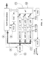
- Fig. 2 shows further an application of the method in connection with a QAM receiver as described above, in which a low intermediate frequency signal 6 is sampled by means of an AD converter 7 in synchronization with an oscillator 8 and which is provided with a symbol rate detector functioning according to the invention.
- the demodulator regulates the voltage-controlled local oscillator 4 and crystal oscillator 8' so as to maintain proper tuning and symbol synchronization.
- Amplification 10 is also controlled by the demodulator 9 in such a manner that the dynamics of AD conversion will be utilized as well as possible.
- This type of traditional QAM receiver is only capable of synchronizing itself with a signal if its carrier frequency and symbol rate are known with a reasonable accuracy, which on the one hand is due to the slowness of synchronization algorithms and on the other hand to the fact that modulation produces very meager information about carrier frequency and symbol rate.
- the invention improves this type of overall system in such a manner that, for example, a separate measuring system as shown in fig. 2 applies e.g. the principle depicted in fig. 3 for measuring the mean frequency and bandwidth of a signal having the low intermediate frequency 6 and adjusts, on the basis thereof, the voltage-controlled oscillators 4, 8 to what is so close to the correct value that the fixed-rate demodulator 9 is capable locking to the signal.
- a separate measuring system as shown in fig. 2 applies e.g. the principle depicted in fig. 3 for measuring the mean frequency and bandwidth of a signal having the low intermediate frequency 6 and adjusts, on the basis thereof, the voltage-controlled oscillators 4, 8 to what is so close to the correct value that the fixed-rate demodulator 9 is capable locking to the signal.
- the sequence of samples is thus preferably guided not only to the demodulator 9 but also to the three power measuring branches 11'.
- Each branch is first provided with a digital narrow bandpass filter 11a, thereafter a combination logic 11b for calculating the square of a sample value or the instantaneous power.
- the power values thus measured are averaged by means of low pass filters 11c.
- the narrow bandpass filters 11c are tuned to frequencies 1 ⁇ 4f N , 1 ⁇ 2f N and 3 ⁇ 4f N , wherein f N is a half of the sample frequency, i.e. the Nyquist frequency.
- Operation of the measuring system is controlled by a micro-controller 12 which reads said three measuring results.
- the controller 12 is provided with a software which concludes from the measurements in which direction the down-conversion frequency 4 and the sample frequency 8 of an AD converter are to be adjusted in order to make the low intermediate frequency 6 equal to the symbol rate and the sample frequency four times higher than the symbol rate.
- parameters c and s have the following values: frequency 1 4 f N 1 2 f N 3 4 f N c 0.5 0 ⁇ 0.5 s 0.5 1 0.5
- the above diagram depicts a special low pass filter used for averaging measured momentary narrow-band outputs. First, four successive samples are summed up. This eliminates the natural sinusoidal fluctuation of momentary output or power at presently used frequencies 1 ⁇ 4f N , 1 ⁇ 2f N and 3 ⁇ 4f N .
- the final step is a simple recursive filtering.
- Parameter g selects the width of a low passband. The less g falls short of one, the narrower is the band i.e. the longer is the integration time.
Landscapes
- Engineering & Computer Science (AREA)
- Computer Networks & Wireless Communication (AREA)
- Signal Processing (AREA)
- Digital Transmission Methods That Use Modulated Carrier Waves (AREA)
Claims (11)
- Verfahren für einen QAM-Empfänger, wobei, wenn mehrstufige Modulation verwendet wird, ein Übertragungssignal (1), das ein digitales Fernseh-, Video- oder ähnliches Bild betrifft, das übertragen werden soll, in einen Tuner (2) abwärts konvertiert und mit einem ersten Filter (3a) auf eine Zwischenfrequenz (5) bandgefiltert wird, woran sich eine weitere nachfolgende Abwärtskonvertierung mittels eines ersten Oszillators (4) und das Filtern mit einem zweiten Filter (3b) auf eine niedrigere Zwischenfrequenz (6) anschließt, die im Wesentlichen gleich der Symbolrate, die bei der Bildübertragung verwendet wird, oder gleich ihres niedrigen ungeraden Mehrfachen ist, wonach ein AD-Wandler (7) unter der Synchronisierung eines zweiten Oszillators (8) verwendet wird, um Proben des verarbeiteten Signals (6) zu einem Demodulator (9) zu geben, der für eine feste Symbolrate vorgesehen ist und in der Lage ist, die Oszillatoren (4, 8) zu regulieren, um mindestens eines oder mehrere der Folgenden zu erhalten: die richtige Abstimmung, Symbolsynchronisation und Verstärkung (10), wobei das Signal mit niedrigerer Zwischenfrequenz (6) mit Hilfe eines Messsystems (11) gemessen wird, das mindestens drei Leistungsmesszweige (11') umfasst, deren Messergebnisse für die Einstellung der Oszillatoren (4, 8) verwendet werden, so dass der Demodulator (9) in der Lage ist, auf das Signal zu verriegeln.
- Verfahren nach Anspruch 1, wobei eine Anfolge von Proben (X), die aus dem verarbeiteten Signal (6) erzeugt werden, zum Demodulator (9) und zu den mindestens drei Leistungsmesszweigen (11') geleitet wird, wobei die drei Messergebnisse, die von den mindestens drei Leistungsmesszweigen bestimmt wurden und die das Übertragungssignal darstellen, zur Steuerung der Oszillatoren (4, 8) mittels eines Mikrocontrollers (12) verwendet werden.
- Verfahren nach Anspruch 2, wobei die Messergebnisse mit Hilfe eines Mikrocontrollers (12) interpretiert werden, um die Abwärtskonvertierungsfrequenz (4) und die Probeentnahmefrequenz (8) eines AD-Wandlers solcherart einzustellen, dass die niedrigere Zwischenfrequenz (6) im Wesentlichen gleich der Symbolrate wird und die Probeentnahmefrequenz das Vierfache der Symbolrate beträgt.
- Verfahren nach Anspruch 2 oder 3, wobei jeder Leistungsmesszweig (11') mindestens mit einem digitalen Schmalbandfilter (11a) und danach mit einer Kombinationslogik (11b) versehen ist, die zum Berechnen der Rechteck- oder Augenblicksleistung eines Probenwertes verwendet werden, gefolgt von der Mittlung der bestimmten Leistungswerte mit Hilfe eines Schmalbandfilters (11c).
- Verfahren gemäß Anspruch 4, wobei die Schmalbandfilter (11a) auf Frequenzen von 1/4 fN, 1/2 fN und 3/4 fN abgestimmt sind, wobei fN für ein Halbes der Probeentnahmefrequenz, d.h. für eine so genannte Nyquist-Frequenz steht.
- Verfahren nach Anspruch 1, wobei die Messung des Signals mit niedrigerer Zwischenfrequenz (6) auf einer Zwischenfrequenz des Signals und der Bandbreite des Spektrums des Signals basiert.
- QAM-Empfänger für mehrstufige Modulation, umfassend einen Tuner (2) zum Abwärtskonvertieren eines Übertragungssignals (1), das ein digitales Fernseh-, Video- oder ähnliches Bild betrifft, das übertragen werden soll, einen ersten Filter (3a) zum Bandfiltern des Signals auf eine Zwischenfrequenz (5), einen ersten Oszillator (4) und einen zweiten Filter (3b) zum weiteren Abwärtskonvertieren und Filtern des Signals auf eine niedrigere Zwischenfrequenz (6), die im Wesentlichen gleich der Symbolrate, die bei der Bildübertragung verwendet wird, oder gleich ihrem niedrigen ungeraden Mehrfachen ist, einen zweiten Oszillator (8) und einen AD-Wandler (7) zur Probeentnahme aus dem Signal unter der Synchronisierung des zweiten Oszillators (8) und einen Demodulator (9), der für eine feste Symbolrate zum Steuern der Oszillatoren (4, 8) vorgesehen ist, um mindestens die richtige Abstimmung und Symbolsynchronisation zu erhalten, und auch zum Steuern der Verstärkung (10), wobei der QAM-Empfänger ein Messsystem (11) umfasst, das mindestens drei Leistungsmesszweige (11') umfasst, um das Signal mit niedrigerer Zwischenfrequenz (6) zu messen, um die Oszillatoren (4, 8) auf der Grundlage der Messergebnisse einzustellen, so dass der Demodulator (9) in der Lage ist, auf das Signal zu verriegeln.
- QAM-Empfänger nach Anspruch 7, wobei das Messsystem (11) die mindestens drei Energiemesszweige (11') umfasst, zu denen eine Abfolge von Proben (X) geleitet wird und außerdem zum Demodulator (9), und der QAM-Empfänger umfasst ferner einen Mikrocontroller (12) zur Steuerung der Oszillatoren (4, 8) auf der Grundlage der mindestens drei Messergebnisse, die das Übertragungssignal darstellen und die von den mindestens drei Leistungsmesszweigen bestimmt wurden.
- QAM-Empfänger nach Anspruch 8, wobei der Mikrocontroller (12), wenn er zum Interpretieren der Messergebnisse angeordnet ist, ferner angeordnet ist, um mindestens die Abwärtskonvertierungsfrequenz (4) und die Probeentnahmefrequenz (8) des AD-Wandlers solcherart einzustellen, dass die niedrigere Zwischenfrequenz (6) im Wesentlichen gleich der Symbolrate sein kann und die Probeentnahmefrequenz das Vierfache der Symbolrate betragen kann.
- QAM-Empfänger nach Anspruch 8 oder 9, wobei jeder Leistungsmesszweig (11') mindestens eine digitalen Schmalbandfilter (11a) und danach ferner eine Kombinationslogik (11b) für jeden Leistungsmesszweig (11') umfasst, die zum Berechnen der Rechteck- oder Augenblicksleistung eines Probenwertes verwendet werden, sowie einen Schmalbandfilter (11c) zur Mittlung der bestimmten Leistungswerte.
- QAM-Empfänger gemäß Anspruch 10, wobei die Schmalbandfilter (11a) auf Frequenzen von 1/4 fN, 1/2 fN und 3/4 fN abgestimmt sind, wobei fN für ein Halbes der Probenfrequenz, d.h. für eine so genannte Nyquist-Frequenz, steht.
Applications Claiming Priority (2)
| Application Number | Priority Date | Filing Date | Title |
|---|---|---|---|
| FI955364A FI98026C (fi) | 1995-11-08 | 1995-11-08 | Menetelmä QAM-vastaanottimen yhteydessä ja QAM-vastaanotin |
| FI955364 | 1995-11-08 |
Publications (3)
| Publication Number | Publication Date |
|---|---|
| EP0773655A2 EP0773655A2 (de) | 1997-05-14 |
| EP0773655A3 EP0773655A3 (de) | 2000-09-13 |
| EP0773655B1 true EP0773655B1 (de) | 2006-10-04 |
Family
ID=8544346
Family Applications (1)
| Application Number | Title | Priority Date | Filing Date |
|---|---|---|---|
| EP96117566A Expired - Lifetime EP0773655B1 (de) | 1995-11-08 | 1996-11-02 | Verfahren und Einrichtung zum Empfang eines QAM-Signals |
Country Status (4)
| Country | Link |
|---|---|
| US (1) | US5892799A (de) |
| EP (1) | EP0773655B1 (de) |
| DE (1) | DE69636592T2 (de) |
| FI (1) | FI98026C (de) |
Families Citing this family (8)
| Publication number | Priority date | Publication date | Assignee | Title |
|---|---|---|---|---|
| US6307896B1 (en) * | 1998-04-03 | 2001-10-23 | Tektronix, Inc. | Instrumentation receiver for digitally modulated radio frequency signals |
| GB2343815B (en) * | 1998-11-12 | 2003-10-22 | Sony Uk Ltd | Digital receiver |
| JP3612224B2 (ja) * | 1998-11-27 | 2005-01-19 | アルプス電気株式会社 | テレビジョン信号受信チューナー |
| AU7346800A (en) * | 1999-09-02 | 2001-03-26 | Automated Business Companies | Communication and proximity authorization systems |
| GB2367700A (en) * | 2000-10-06 | 2002-04-10 | Mitel Semiconductor Ltd | A single conversion tuner comprising a tracking filter and an image reject mixer |
| EP1633096A1 (de) * | 2004-08-26 | 2006-03-08 | St Microelectronics S.A. | Bestimmung der Träger- und Symbolfrequenz eines Signals |
| US9184964B2 (en) * | 2013-05-02 | 2015-11-10 | Comtech Ef Data Corp. | Low symbol rate rapid carrier acquisition with extremely large frequency offset for digital communication receiver |
| JP2019106575A (ja) * | 2017-12-08 | 2019-06-27 | ルネサスエレクトロニクス株式会社 | 無線受信機、及び中間周波数信号生成方法 |
Family Cites Families (8)
| Publication number | Priority date | Publication date | Assignee | Title |
|---|---|---|---|---|
| GB2153186B (en) * | 1984-01-13 | 1987-04-23 | Ncr Co | Digital data receiver including timing adjustment circuit |
| US5175626A (en) * | 1991-07-25 | 1992-12-29 | Rca Thomson Licensing Corporation | Apparatus providing a clock signal for a digital television receiver in response to a channel change |
| US5235424A (en) * | 1992-02-06 | 1993-08-10 | General Electric Company | Automatic gain control system for a high definition television signal receiver |
| US5268761A (en) * | 1992-08-19 | 1993-12-07 | Rca Thomson Licensing Corporation | Automatic gain control system for a high definition television signal receiver including an adaptive equalizer |
| JPH0795175A (ja) * | 1993-09-27 | 1995-04-07 | Toshiba Corp | Ofdm信号復調装置 |
| JP3041175B2 (ja) * | 1993-11-12 | 2000-05-15 | 株式会社東芝 | Ofdm同期復調回路 |
| US5588025A (en) * | 1995-03-15 | 1996-12-24 | David Sarnoff Research Center, Inc. | Single oscillator compressed digital information receiver |
| US5694419A (en) * | 1995-11-07 | 1997-12-02 | Hitachi America, Ltd. | Shared resource modulator-demodulator circuits for use with vestigial sideband signals |
-
1995
- 1995-11-08 FI FI955364A patent/FI98026C/fi active IP Right Grant
-
1996
- 1996-11-02 DE DE69636592T patent/DE69636592T2/de not_active Expired - Lifetime
- 1996-11-02 EP EP96117566A patent/EP0773655B1/de not_active Expired - Lifetime
- 1996-11-07 US US08/744,866 patent/US5892799A/en not_active Expired - Fee Related
Non-Patent Citations (1)
| Title |
|---|
| PROAKIS: "Digital Communications", 1989 * |
Also Published As
| Publication number | Publication date |
|---|---|
| EP0773655A2 (de) | 1997-05-14 |
| FI98026C (fi) | 1997-03-25 |
| DE69636592D1 (de) | 2006-11-16 |
| FI955364A0 (fi) | 1995-11-08 |
| DE69636592T2 (de) | 2007-08-16 |
| FI98026B (fi) | 1996-12-13 |
| US5892799A (en) | 1999-04-06 |
| EP0773655A3 (de) | 2000-09-13 |
Similar Documents
| Publication | Publication Date | Title |
|---|---|---|
| KR100713109B1 (ko) | 디지털 변조된 무선 주파수 신호를 위한 계측용 수신기 | |
| US7639996B2 (en) | Simplified high frequency tuner and tuning method | |
| DE69400162T2 (de) | Digitaler Empfänger für Übertragungen veränderlicher Symbolraten | |
| KR100413715B1 (ko) | 응답시간이제어가능한위상동기루프를포함하는장치 | |
| CN1197376C (zh) | 在用户端具有频率漂移校正的无线通讯系统 | |
| US6133964A (en) | Digital demodulator and method therefor | |
| DE69633830T2 (de) | Gerät zur demodulierung und dekodierung von videosignalen | |
| EP0782270B1 (de) | Abstimmsystem für Satellitenempfänger mit Feinabstimmungseinrichtung | |
| WO1991002421A1 (de) | Verfahren und vorrichtung zum umsetzen digital modulierter empfangssignale aus dem hochfrequenzbereich | |
| CN1191056A (zh) | 数字卫星接收机调谐器的表面声波滤波器 | |
| DE68916952T2 (de) | Selbsttätige Frequenz-Steuerschaltung. | |
| EP0773655B1 (de) | Verfahren und Einrichtung zum Empfang eines QAM-Signals | |
| DE69733706T2 (de) | Empfänger für digitalen Rundfunk | |
| US5130802A (en) | Television receiving section having an a/d converter which simultaneously performs synchronous demodulation | |
| US20030067555A1 (en) | Dual hdtv/ntsc receiving method using symbol timing recovery and sync signal detection and apparatus thereof | |
| KR100743444B1 (ko) | 디지털 신호를 위한 수신기를 튜닝하는 방법, 및 수신기 | |
| US6370367B1 (en) | Method for improving the quality of reception in a radio receiver and a radio receiver | |
| JP3036460B2 (ja) | Afc回路 | |
| DE10245687B4 (de) | Frequenzfehlerkorrektur in einem Übertragungssystem | |
| KR19990060480A (ko) | 디지털 잔류측파대 복조장치 | |
| US6026128A (en) | Frequency- and phase regulator device for VSB receivers | |
| KR0162437B1 (ko) | 디지탈 위성방송 수신기의 주파수 자동 미세 조정장치 및 방법 | |
| DE10157864B4 (de) | Quadratur-Amplituden-Modulations- (QAM) Empfänger | |
| DE69735299T2 (de) | Demodulator mit digitaler träger- und taktrückgewinnungsschaltung | |
| HK1015563B (en) | Tuner for digital satellite receiver |
Legal Events
| Date | Code | Title | Description |
|---|---|---|---|
| PUAI | Public reference made under article 153(3) epc to a published international application that has entered the european phase |
Free format text: ORIGINAL CODE: 0009012 |
|
| AK | Designated contracting states |
Kind code of ref document: A2 Designated state(s): DE FR GB IT |
|
| PUAL | Search report despatched |
Free format text: ORIGINAL CODE: 0009013 |
|
| AK | Designated contracting states |
Kind code of ref document: A3 Designated state(s): DE FR GB IT |
|
| 17P | Request for examination filed |
Effective date: 20000921 |
|
| RAP1 | Party data changed (applicant data changed or rights of an application transferred) |
Owner name: NOKIA TECHNOLOGY GMBH |
|
| RAP1 | Party data changed (applicant data changed or rights of an application transferred) |
Owner name: NOKIA TECHNOLOGY GMBH |
|
| 17Q | First examination report despatched |
Effective date: 20050606 |
|
| GRAP | Despatch of communication of intention to grant a patent |
Free format text: ORIGINAL CODE: EPIDOSNIGR1 |
|
| GRAS | Grant fee paid |
Free format text: ORIGINAL CODE: EPIDOSNIGR3 |
|
| GRAA | (expected) grant |
Free format text: ORIGINAL CODE: 0009210 |
|
| AK | Designated contracting states |
Kind code of ref document: B1 Designated state(s): DE FR GB IT |
|
| PG25 | Lapsed in a contracting state [announced via postgrant information from national office to epo] |
Ref country code: IT Free format text: LAPSE BECAUSE OF FAILURE TO SUBMIT A TRANSLATION OF THE DESCRIPTION OR TO PAY THE FEE WITHIN THE PRESCRIBED TIME-LIMIT;WARNING: LAPSES OF ITALIAN PATENTS WITH EFFECTIVE DATE BEFORE 2007 MAY HAVE OCCURRED AT ANY TIME BEFORE 2007. THE CORRECT EFFECTIVE DATE MAY BE DIFFERENT FROM THE ONE RECORDED. Effective date: 20061004 |
|
| REG | Reference to a national code |
Ref country code: GB Ref legal event code: FG4D |
|
| REF | Corresponds to: |
Ref document number: 69636592 Country of ref document: DE Date of ref document: 20061116 Kind code of ref document: P |
|
| ET | Fr: translation filed | ||
| PLBE | No opposition filed within time limit |
Free format text: ORIGINAL CODE: 0009261 |
|
| STAA | Information on the status of an ep patent application or granted ep patent |
Free format text: STATUS: NO OPPOSITION FILED WITHIN TIME LIMIT |
|
| 26N | No opposition filed |
Effective date: 20070705 |
|
| PGFP | Annual fee paid to national office [announced via postgrant information from national office to epo] |
Ref country code: FR Payment date: 20101123 Year of fee payment: 15 |
|
| PGFP | Annual fee paid to national office [announced via postgrant information from national office to epo] |
Ref country code: DE Payment date: 20101027 Year of fee payment: 15 |
|
| PGFP | Annual fee paid to national office [announced via postgrant information from national office to epo] |
Ref country code: IT Payment date: 20101112 Year of fee payment: 15 Ref country code: GB Payment date: 20101027 Year of fee payment: 15 |
|
| GBPC | Gb: european patent ceased through non-payment of renewal fee |
Effective date: 20111102 |
|
| REG | Reference to a national code |
Ref country code: FR Ref legal event code: ST Effective date: 20120731 |
|
| PG25 | Lapsed in a contracting state [announced via postgrant information from national office to epo] |
Ref country code: IT Free format text: LAPSE BECAUSE OF NON-PAYMENT OF DUE FEES Effective date: 20111102 |
|
| PG25 | Lapsed in a contracting state [announced via postgrant information from national office to epo] |
Ref country code: GB Free format text: LAPSE BECAUSE OF NON-PAYMENT OF DUE FEES Effective date: 20111102 |
|
| PG25 | Lapsed in a contracting state [announced via postgrant information from national office to epo] |
Ref country code: FR Free format text: LAPSE BECAUSE OF NON-PAYMENT OF DUE FEES Effective date: 20111130 |
|
| REG | Reference to a national code |
Ref country code: DE Ref legal event code: R119 Ref document number: 69636592 Country of ref document: DE Effective date: 20130601 |
|
| PG25 | Lapsed in a contracting state [announced via postgrant information from national office to epo] |
Ref country code: DE Free format text: LAPSE BECAUSE OF NON-PAYMENT OF DUE FEES Effective date: 20130601 |