EP0773832B1 - Leicht zu beladende halteeinrichtung für einen versorgungsschlauch einer zentrifuge - Google Patents
Leicht zu beladende halteeinrichtung für einen versorgungsschlauch einer zentrifuge Download PDFInfo
- Publication number
- EP0773832B1 EP0773832B1 EP96921227A EP96921227A EP0773832B1 EP 0773832 B1 EP0773832 B1 EP 0773832B1 EP 96921227 A EP96921227 A EP 96921227A EP 96921227 A EP96921227 A EP 96921227A EP 0773832 B1 EP0773832 B1 EP 0773832B1
- Authority
- EP
- European Patent Office
- Prior art keywords
- holder
- umbilicus
- carrier
- cavity
- support block
- Prior art date
- Legal status (The legal status is an assumption and is not a legal conclusion. Google has not performed a legal analysis and makes no representation as to the accuracy of the status listed.)
- Expired - Lifetime
Links
- 210000001113 umbilicus Anatomy 0.000 title claims description 47
- 239000012530 fluid Substances 0.000 claims abstract description 6
- 230000000717 retained effect Effects 0.000 abstract description 2
- 210000004369 blood Anatomy 0.000 description 8
- 239000008280 blood Substances 0.000 description 8
- 239000000463 material Substances 0.000 description 6
- 229920003023 plastic Polymers 0.000 description 5
- 239000004033 plastic Substances 0.000 description 5
- 239000000306 component Substances 0.000 description 3
- 238000010276 construction Methods 0.000 description 3
- 210000001772 blood platelet Anatomy 0.000 description 2
- 238000000034 method Methods 0.000 description 2
- 238000000926 separation method Methods 0.000 description 2
- 229920011453 Hytrel® 4056 Polymers 0.000 description 1
- 239000012503 blood component Substances 0.000 description 1
- 238000005119 centrifugation Methods 0.000 description 1
- 238000004891 communication Methods 0.000 description 1
- 210000003743 erythrocyte Anatomy 0.000 description 1
- 238000002347 injection Methods 0.000 description 1
- 239000007924 injection Substances 0.000 description 1
- 210000002381 plasma Anatomy 0.000 description 1
- 229920000915 polyvinyl chloride Polymers 0.000 description 1
- 239000004800 polyvinyl chloride Substances 0.000 description 1
- 239000002904 solvent Substances 0.000 description 1
- 230000001225 therapeutic effect Effects 0.000 description 1
- 229920002554 vinyl polymer Polymers 0.000 description 1
Images





Classifications
-
- B—PERFORMING OPERATIONS; TRANSPORTING
- B04—CENTRIFUGAL APPARATUS OR MACHINES FOR CARRYING-OUT PHYSICAL OR CHEMICAL PROCESSES
- B04B—CENTRIFUGES
- B04B5/00—Other centrifuges
- B04B5/04—Radial chamber apparatus for separating predominantly liquid mixtures, e.g. butyrometers
- B04B5/0442—Radial chamber apparatus for separating predominantly liquid mixtures, e.g. butyrometers with means for adding or withdrawing liquid substances during the centrifugation, e.g. continuous centrifugation
-
- B—PERFORMING OPERATIONS; TRANSPORTING
- B04—CENTRIFUGAL APPARATUS OR MACHINES FOR CARRYING-OUT PHYSICAL OR CHEMICAL PROCESSES
- B04B—CENTRIFUGES
- B04B5/00—Other centrifuges
- B04B5/04—Radial chamber apparatus for separating predominantly liquid mixtures, e.g. butyrometers
- B04B5/0442—Radial chamber apparatus for separating predominantly liquid mixtures, e.g. butyrometers with means for adding or withdrawing liquid substances during the centrifugation, e.g. continuous centrifugation
- B04B2005/045—Radial chamber apparatus for separating predominantly liquid mixtures, e.g. butyrometers with means for adding or withdrawing liquid substances during the centrifugation, e.g. continuous centrifugation having annular separation channels
-
- B—PERFORMING OPERATIONS; TRANSPORTING
- B04—CENTRIFUGAL APPARATUS OR MACHINES FOR CARRYING-OUT PHYSICAL OR CHEMICAL PROCESSES
- B04B—CENTRIFUGES
- B04B5/00—Other centrifuges
- B04B5/04—Radial chamber apparatus for separating predominantly liquid mixtures, e.g. butyrometers
- B04B5/0442—Radial chamber apparatus for separating predominantly liquid mixtures, e.g. butyrometers with means for adding or withdrawing liquid substances during the centrifugation, e.g. continuous centrifugation
- B04B2005/0492—Radial chamber apparatus for separating predominantly liquid mixtures, e.g. butyrometers with means for adding or withdrawing liquid substances during the centrifugation, e.g. continuous centrifugation with fluid conveying umbilicus between stationary and rotary centrifuge parts
Definitions
- the invention relates to centrifugal processing systems and apparatus.
- centrifuge equipment in association with single use, sterile processing chambers, typically made of plastic.
- the centrifuge equipment introduces whole blood into these chambers while rotating them to create a centrifugal field.
- Some conventional centrifuges employ an umbilicus to establish sealless fluid-flow connection between rotating and stationary components.
- the processing chamber and the support comprise an integrally molded unit.
- the tube holder that embodies the features of the invention is ideally suited for holding a multiple lumen umbilicus that communicates with the processing chamber.
- the tube holder allows straightforward attachment and removal of the umbilicus, always in a prescribed manner and with a single hand.
- the holder that embodies the features of the invention securely retains the umbilicus during use in a closed, protected environment, safeguarding it against inadvertent dislodgement, removal, or damage.
- Fig. 1 shows a blood centrifuge 10 having a blood processing chamber 12.
- the boundaries of the chamber 12 are formed by a flexible processing container 14 carried within an annular gap 16 between a rotating spool element 18 and bowl element 20.
- the processing container 14 takes the form of an elongated tube, which is wrapped about the spool element 18 before use.
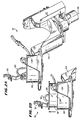
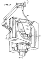
- the bowl and spool elements 18 and 20 are pivoted on a yoke 22 between an upright position for loading and unloading of the container 14, as Figs. 2A/2B show, and a suspended position for operation, as Figs. 1 and 3 show.
- the bowl and spool elements 18 and 20 When upright (see Fig. 2A), the bowl and spool elements 18 and 20 are presented for access by the user.
- a mechanism (not shown) permits the spool and bowl elements 18 and 20 to assume a mutually separated position, as Fig. 2B shows. In this position, the spool element 18 is at least partially out of the interior area of the bowl element 20 to expose the exterior spool surface for access.
- the user can wrap the container 14 about the spool element 18, as Figs. 4 and 5 show (for simplicity of illustration, Figs. 4 and 5 do not show the bowl element 20).
- Pins 24 on the spool element 18 (see Figs. 4 and 5) engage cutouts 26 on the container 14 to secure the container 14 on the spool element 18.
- the mechanism also permits the spool and bowl elements 18 and 20 to assume a mutually cooperating position, as Fig. 2A shows. In this position, the spool element 18 and the secured container 14 are enclosed within the interior area of the bowl element 20.
- spool and bowl elements 18 and 20 When closed, the spool and bowl elements 18 and 20 can be pivoted into a suspended position, as Figs. 1 and 3 show. When suspended, the bowl and spool elements 18 and 20 are in position for operation.
- An umbilicus 30 (see Fig. 1) establishes communication between the interior of the processing container 14 within the centrifugal field and pumps and other stationary components located outside the centrifugal field.
- the umbilicus is preferably made of a high modulus Hytrel ® Plastic Material (DuPont), like Hytrel ® 4056 Material.
- Hytrel ® 4056 Material As the spool and bowl elements 18 and 20 rotate about the axis 28, whole blood and separated blood components are conveyed through lumens in the umbilicus 30 into and out of the container 14.
- a non-rotating (zero omega) holder 32 holds the upper portion of the umbilicus 30 in a non-rotating position above the suspended spool and bowl elements 18 and 20.
- a holder 34 on the yoke 22 rotates the mid-portion of the umbilicus 30 at a first (one omega) speed about the suspended spool and bowl elements 18 and 20.
- Another holder 36 rotates the lower end of the umbilicus 30 at a second speed twice the one omega speed (the two omega speed), at which the suspended spool and bowl elements 18 and 20 also rotate. This known relative rotation of the umbilicus 30 keeps it untwisted, in this way avoiding the need for rotating seals.
- Figs. 4 to 10 show further details of the construction and operation of the lower umbilicus holder 36.
- the holder 36 simplifies the loading and unloading of the umbilicus 30 by the operator before and after use.
- the holder 36 provides a secure and protected enclosure for retaining the umbilicus 30 during use.
- the holder 36 includes a carrier 38 for receiving a support block 40 on the umbilicus 30.
- the support block 40 is preferably made from a softer and more flexible Hytrel® Plastic Material; for example, Hytrel® 8122 Material.
- the support block 40 is injection over-molded about the umbilicus 30.
- the support block 40 includes formed lumens 42 which communicate with the lumens in the umbilicus 30.
- Medical grade polyvinyl tubes 44 are secured by solvent bonding to the support block lumens 42.
- the tubes 44 are secured at their opposite ends to ports 46 communicating with the container 14.
- the support block 40 also preferably includes an integral molded flange 48.
- the flange 48 has a predetermined shape, which can vary. In the illustrated embodiment, the flange 48 is generally D-shaped.
- the carrier 38 includes a preformed cavity 52 shaped to mate with the support block 40 and flange 48 on the umbilicus 30.
- the carrier 38 is pivotally mounted within the supports 50.
- the supports 50 and spool element 18 form an integrally molded assembly, made from a durable plastic material like polyvinyl chloride.
- the carrier 38 is also separately molded from this or another plastic material.
- the carrier 38 is attached by a pivot pin 54 extending between the supports 50. The carrier 38 swings between two positions about the pivot pin 54.
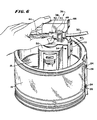
- the carrier cavity 52 is exposed outside the supports 50 in a generally horizontal position for receiving the support block 40 and flange 48 in a single, predetermined way. More particularly, with the container 14 properly secured to the spool element 18 (see Fig. 6), the support block 40 and flange 48 fit within the carrier cavity 52 with the tubing 44 facing towards the container ports 46. As Fig. 6 shows, the operator is able to conveniently slide the support block 40 and flange 48 easily into the carrier cavity 52 with one hand.
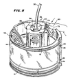
- the operator is also able pivot the carrier 38 and the support block 40 and flange 48 it carries into a second or closed position (see Fig. 8).
- the carrier cavity 52 and support block 40 and flange 48 are located in a generally vertical position, enclosed by the supports 50.
- the tubing 44 leading to the container 14 is placed into slight tension.
- the tubing 14 extends in this condition from the carrier cavity 52 (which now points towards the bottom of the spool element 18) upward through the open interior of the spool element 18 to an edge 56 against which the container ports 46 rest.
- the holder 36 further includes a latch mechanism 60, which releasably locks the carrier 38 in its second or closed position.
- the details of construction for the latch mechanism 60 can vary.
- the latch mechanism 60 includes a latch bar 62 carried for movement in a channel 64 in the rear of one of the supports 50.
- the latch bar 62 moves in the channel 64 in a path generally perpendicular to the axis of the pivot pin 54.
- the carrier 38 includes a keyway 58 (see also Fig. 4) that fits into the latch slot 68 when the carrier 38 is in its second or closed position.
- the cam member 74 has an eccentric surface 78 that rests against the latch bar 62 at the end 80 opposite to the latch finger 66.
- the spring 70 continuously urges the latch bar end 80 against the surface 78.
- the eccentric surface 78 has a first, generally flat region 82 that is presented to latch bar end 80 when the latch tab 72 is disposed in its unlatched position.
- the latch bar 62 occupies its normally biased position holding the latch finger 66 free of the latch slot 68.
- the eccentric surface 78 has a second, generally curved region 84 spaced radially farther from the pin 54 than the flat region 82.
- the curved region 84 urges the latch bar 62 against the biasing force of the spring 70 to advance the latch finger 66 into the latch slot 68 (see Fig. 10).
- the latch finger 66 also registers with the carrier keyway 58, locking the carrier 38 in its closed position. Subsequent movement of the latch tab 72 toward its unlatched position progressively presents the flat cam region 82 to the latch end 80, allowing the spring-assisted return of the latch bar 62 to its normally biased position.
- the carrier 38 is free to be moved by the operator back to its open position for removal of the umbilicus support block 40 and flange 48.
- a lip 88 is provided on the carrier 38 to assist in flipping-up the unlatched carrier 38.
- a spring 86 is also provided (see Figs. 9 and 10) to further assist movement of the carrier 38, when unlatched, from its closed position toward its opened position.
- the operator wraps the container 14 about the spool element 18.
- the carrier 38 is in its opened position awaiting loading of the umbilicus support block 40 and flange 48.
- the latch tab 72 is likewise located in its unlatched position.
- the operator After securing the container 14 to the spool element 18, the operator then fits the support block 40 and flange 48 into the open carrier cavity 52 (see Fig. 6). The operator closes the carrier 38, as Fig. 7 shows, and then presses the latch tab 72 into its latched position, as Fig. 8 shows.
- the operator reverses these steps in removing the umbilicus block 40 from the carrier 38.
- the holder 38 as just described provides straightforward attachment and removal of the umbilicus block 40 and flange 48, always in the prescribed manner and with a single hand .
- the holder 38 securely retains the umbilicus block 40 and flange 48 during use in a closed, protected environment, safeguarding it against inadvertent dislodgement, removal, or damage.
Landscapes
- Centrifugal Separators (AREA)
Claims (12)
- Verarbeitungselement für eine Zentrifuge (10), die folgendes aufweistwobei der Träger (38) um den Stift (54) an der Abstützung (50) schwenkbar ist zwischen einer geöffneten Position, in der der Schlauchhalter (36) von dem Hohlraum weg geschwenkt ist, um den Zugang zu dem Schlauchhalter für die Aufnahme der Schläuche zu öffnen, und einer geschlossenen Position, in der der Schlauchhalter (36) in den Hohlraum geschwenkt ist, um den Zugang zu dem Schlauchhalter zu schließen und die Schläuche während der Verarbeitung in dem Schlauchhalter zu halten.eine Kammer (12) zur Aufnahmen von Fluiden, die einem Zentrifugalkraftfeld auszusetzen sind,einen Träger (38) an dem Verarbeitungselement, der einen Schlauchhalter (36) bildet, um Schläuche aufzunehmen, die im Gebrauch Fluide zu oder aus der Kammer (12) transportieren,eine Abstützung (50) an dem Verarbeitungselement, die Wände hat, die einen Hohlraum bilden,und einen Stift (54), der den Träger mit der Abstützung (50) verbindet,
- Verarbeitungselement nach Anspruch 1,
wobei der Schlauchhalter einen Hohlraum (52) aufweist, der eine Form hat, die mit einem Abstützblock (40) zusammenpaßt, der von den in dem Schlauchhalter (36) aufgenommenen Schläuchen getragen wird. - Zentrifuge (10), die folgendes aufweist:ein Verarbeitungselement, das drehbar angebracht ist und eine Kammer (12) zur Aufnahme von Fluiden aufweist, die einem Zentrifugalkraftfeld auszusetzen sind,ein Versorgungsteil (30) zum Transport von Fluid zu oder aus der Kammer (12),einen Träger (38) an dem Verarbeitungselement, der einen Halter (36) zur Aufnahme des Versorgungsteils (30) bildet,eine Abstützung (50) an dem Verarbeitungselement, die Wände hat, die einen Hohlraum bilden, undeinen Stift (54), der den Träger (38) mit der Abstützung (50) verbindet, wobei der Träger (38) um den Stift (54) an der Abstützung (50) schwenkbar ist zwischen einer geöffneten Position, in der der Halter (36) von dem Hohlraum weg geschwenkt ist, um den Zugang zu dem Halter für die Aufnahme des Versorgungsteils (30) zu öffnen, und einer geschlossenen Position, in der der Halter (36) in den Hohlraum geschwenkt ist, um den Zugang zu dem Halter zu schließen und das Versorgungsteil (30) während der Drehung des Verarbeitungselements in dem Halter zu halten.
- Zentrifuge nach Anspruch 3,
wobei das Versorgungsteil (30) einen Abstützblock (40) aufweist und wobei der Halter (36) einen Hohlraum (52) aufweist, der eine vorbestimmte Form hat, um mit dem Abstützblock (40) zusammenzupassen. - Zentrifuge (10) nach Anspruch 3,
die folgendes aufweist:ein Jochelement (22), das um eine Drehachse drehbar ist,einen ersten Halter (32);einen zweiten Halter (34) an dem Jochelement (22); undeinen dritten Halter (36) an der Kammer (12), der den Träger (38) aufweist,wobei die Kammer (12) zur Drehung um eine mit der Drehachse ausgefluchtete zweite Achse (28) angebracht ist;wobei das Versorgungsteil (30) folgendes aufweist: ein proximales Ende, ein distales Ende und einen Mittelbereich zwischen dem proximalen und dem distalen Ende, einen ersten Abstützblock in dem proximalen Ende, einen zweiten Abstützblock (40) in dem distalen Ende und einen dritten Abstützblock in dem Mittelbereich, der von dem ersten und dem zweiten Abstützblock beabstandet ist;wobei der erste Halter (32) den ersten Abstützblock während der Drehung des Jochelements (22) stationär an einer Stelle über dem Jochelement in Ausfluchtung mit der Drehachse hält;wobei der zweite Halter (34) den dritten Abstützblock während der Drehung des Jochelements (22) um den mittleren Versorgungsteilbereich drehbar hält;wobei der dritte Halter (36) so ausgebildet ist, daß er den zweiten Abstützblock (40) aufnimmt und den zweiten Abstützblock (40) während der Drehung des Jochelements (22) um die zweite Achse (28) drehbar hält; und wobei dann,wenn der Träger (38) in der geöffneten Position ist, der Halter (36) von dem Hohlraum weg geschwenkt ist, um den Zugang zu dem Halter (36) für die Aufnahme des zweiten Abstützblocks (40) zu öffnen, undwenn der Träger (38) in der geschlossenen Position ist, der Halter (36) in den Hohlraum geschwenkt ist, um den Zugang zu dem Halter (36) zu schließen und den zweiten Abstützblock (40) während der Drehung der Kammer (12) in dem Halter zu halten. - Zentrifuge nach Anspruch 5,
die ferner einen Motor aufweist, um das Jochelement (22) zu drehen und dadurch die Kammer (12) in Drehung zu versetzen, während das Versorgungsteil (30) bei jeder Umdrehung des Jochelements (22) eine Drehung um seine Achse ausführt, wobei die Drehung, in die die Kammer (12) versetzt wird, die doppelte Drehrate der Drehrate des Jochelements (22) hat, so daß dadurch das Versorgungsteil (30) unverdreht gehalten wird. - Zentrifuge nach Anspruch 5 oder 6,
wobei der zweite Abstützblock (40) eine Form hat und wobei der Halter einen Hohlraum (52) aufweist, der so ausgebildet ist, daß er mit der Form des zweiten Abstützblocks (40) zusammenpaßt. - Verarbeitungselement nach Anspruch 1 oder 2 oder
Zentrifuge nach Anspruch 3, 4, 5, 6 oder 7,
wobei das Verarbeitungselement und die Abstützung (50) eine integral geformte Einheit aufweisen. - Zentrifuge nach Anspruch 3,
die folgendes aufweist:ein Becherelement (20), das einen Innenbereich hat, ein Spindelelement (18), das eine äußere Oberfläche hat, und eine Einrichtung, die das Spindelelement und das Becherelement verbindet zur Bewegung zwischen einer miteinander zusammenwirkenden Position, in der das Spindelelement (18) in dem Innenbereich des Becherelements (20) eingeschlossen ist, um die Kammer (12) zwischen der Becherwand und der äußeren Spindeloberfläche zu bilden, und einer voneinander getrennten Position, in der sich das Spindelelement (18) zumindest teilweise außerhalb des Innenbereichs des Becherelements (20) befindet, um die äußere Spindeloberfläche zur Anbringung eines flexiblen Verarbeitungsbehälters (14) freizugeben, der vorher angebrachte Schläuche (44) hat, wobei der Träger (38), der den Halter (36) für die Aufnahme des Versorgungsteils (30) bildet, an dem Becherelement (20) angeordnet ist. - Verarbeitungselement nach Anspruch 1 oder 2 oder
Zentrifuge nach einem der Ansprüche 3 bis 9,
das/die ferner einen Riegel (60) zum lösbaren Festlegen des Trägers (38) in der geschlossenen Position aufweist. - Zentrifuge nach Anspruch 9,
wobei das Versorgungsteil einen Abstützblock (40) aufweist, der eine Form hat, und wobei der Halter (36) einen Hohlraum (52) aufweist, der so ausgebildet ist, daß er mit der Form des Abstützblocks (40) zusammenpaßt. - Zentrifuge nach Anspruch 9,
wobei das Becherelement (20) und die Abstützung (50) eine integral geformte Einheit aufweisen.
Applications Claiming Priority (3)
| Application Number | Priority Date | Filing Date | Title |
|---|---|---|---|
| US480488 | 1995-06-07 | ||
| US08/480,488 US5704887A (en) | 1995-06-07 | 1995-06-07 | Easy load umbilicus holder for a centrifuge |
| PCT/US1996/007839 WO1996040440A1 (en) | 1995-06-07 | 1996-05-22 | Easy load umbilicus holder for a centrifuge |
Publications (3)
| Publication Number | Publication Date |
|---|---|
| EP0773832A1 EP0773832A1 (de) | 1997-05-21 |
| EP0773832A4 EP0773832A4 (de) | 1998-12-23 |
| EP0773832B1 true EP0773832B1 (de) | 2003-03-05 |
Family
ID=23908160
Family Applications (1)
| Application Number | Title | Priority Date | Filing Date |
|---|---|---|---|
| EP96921227A Expired - Lifetime EP0773832B1 (de) | 1995-06-07 | 1996-05-22 | Leicht zu beladende halteeinrichtung für einen versorgungsschlauch einer zentrifuge |
Country Status (8)
| Country | Link |
|---|---|
| US (1) | US5704887A (de) |
| EP (1) | EP0773832B1 (de) |
| JP (1) | JPH10507408A (de) |
| AU (1) | AU699707B2 (de) |
| CA (1) | CA2195196A1 (de) |
| DE (1) | DE69626461T2 (de) |
| NO (1) | NO970539L (de) |
| WO (1) | WO1996040440A1 (de) |
Families Citing this family (24)
| Publication number | Priority date | Publication date | Assignee | Title |
|---|---|---|---|---|
| JP2967055B2 (ja) | 1996-10-14 | 1999-10-25 | 株式会社シスト | 濾過装置 |
| SE9700495D0 (sv) | 1997-02-12 | 1997-02-12 | Omega Medicinteknik Ab | Metod och rundpåsesystem samt centrifug för behandling av blod |
| DE19803534C2 (de) * | 1998-01-30 | 1999-11-11 | Fresenius Ag | Zentrifuge und Leitung zum Zuführen und/oder Abführen mindestens eines Fluids von der Separationseinheit einer Zentrifuge zu einer ortsfesten Anschlußstelle |
| US7001321B1 (en) * | 1998-03-30 | 2006-02-21 | Baxter International Inc. | Carrier for holding a flexible fluid processing container |
| SE516321C2 (sv) * | 1999-05-31 | 2001-12-17 | Gambro Inc | Centrifug för behandling av blod och blodkomponenter |
| US6348156B1 (en) * | 1999-09-03 | 2002-02-19 | Baxter International Inc. | Blood processing systems and methods with sensors to detect contamination due to presence of cellular components or dilution due to presence of plasma |
| SE517032C2 (sv) | 1999-10-26 | 2002-04-02 | Gambro Inc | Sätt och anordning för behandling av blod och blodkomponenter |
| US7008366B1 (en) * | 2000-10-27 | 2006-03-07 | Zymequest, Inc. | Circumferentially driven continuous flow centrifuge |
| US6890291B2 (en) | 2001-06-25 | 2005-05-10 | Mission Medical, Inc. | Integrated automatic blood collection and processing unit |
| DE10142744C1 (de) * | 2001-08-31 | 2003-05-22 | Fresenius Hemocare Gmbh | Zentrifuge |
| US20030173274A1 (en) * | 2002-02-01 | 2003-09-18 | Frank Corbin | Blood component separation device, system, and method including filtration |
| US7211037B2 (en) * | 2002-03-04 | 2007-05-01 | Therakos, Inc. | Apparatus for the continuous separation of biological fluids into components and method of using same |
| US7479123B2 (en) | 2002-03-04 | 2009-01-20 | Therakos, Inc. | Method for collecting a desired blood component and performing a photopheresis treatment |
| US7279107B2 (en) * | 2002-04-16 | 2007-10-09 | Gambro, Inc. | Blood component processing system, apparatus, and method |
| US7037428B1 (en) * | 2002-04-19 | 2006-05-02 | Mission Medical, Inc. | Integrated automatic blood processing unit |
| US20050049539A1 (en) * | 2003-09-03 | 2005-03-03 | O'hara Gerald P. | Control system for driving fluids through an extracorporeal blood circuit |
| US7476209B2 (en) * | 2004-12-21 | 2009-01-13 | Therakos, Inc. | Method and apparatus for collecting a blood component and performing a photopheresis treatment |
| US8257239B2 (en) * | 2010-06-15 | 2012-09-04 | Fenwal, Inc. | Umbilicus for use in an umbilicus-driven fluid processing |
| US9383044B2 (en) | 2013-02-15 | 2016-07-05 | Fenwal, Inc. | Low cost umbilicus without overmolding |
| US9545637B2 (en) * | 2015-04-22 | 2017-01-17 | Fenwal, Inc. | Bearing for umbilicus of a fluid processing system |
| USD844805S1 (en) | 2016-02-29 | 2019-04-02 | President And Fellows Of Harvard College | Holder |
| USD846755S1 (en) * | 2016-12-07 | 2019-04-23 | President And Fellows Of Harvard College | Holder |
| US11898967B2 (en) * | 2021-02-02 | 2024-02-13 | Fenwal, Inc. | Predicting malfunction and failure of centrifuge umbilicus |
| US20230310725A1 (en) * | 2022-03-10 | 2023-10-05 | Terumo Bct, Inc. | Moving blood component collection loop holder |
Family Cites Families (4)
| Publication number | Priority date | Publication date | Assignee | Title |
|---|---|---|---|---|
| US4109852A (en) * | 1977-10-21 | 1978-08-29 | Baxter Travenol Laboratories, Inc. | Centrifugal strain relief sheath for processing apparatus |
| US5370802A (en) * | 1987-01-30 | 1994-12-06 | Baxter International Inc. | Enhanced yield platelet collection systems and methods |
| EP0572656B1 (de) * | 1991-12-23 | 1997-11-05 | Baxter International Inc. | Zentrifuge wobei korb und spule trennbar sind zum verschaffen von zugang zur trennkammer |
| US5514069A (en) * | 1993-12-22 | 1996-05-07 | Baxter International Inc. | Stress-bearing umbilicus for a compact centrifuge |
-
1995
- 1995-06-07 US US08/480,488 patent/US5704887A/en not_active Expired - Fee Related
-
1996
- 1996-05-22 DE DE69626461T patent/DE69626461T2/de not_active Expired - Fee Related
- 1996-05-22 WO PCT/US1996/007839 patent/WO1996040440A1/en not_active Ceased
- 1996-05-22 JP JP9500777A patent/JPH10507408A/ja not_active Ceased
- 1996-05-22 AU AU62498/96A patent/AU699707B2/en not_active Ceased
- 1996-05-22 CA CA002195196A patent/CA2195196A1/en not_active Abandoned
- 1996-05-22 EP EP96921227A patent/EP0773832B1/de not_active Expired - Lifetime
-
1997
- 1997-02-06 NO NO970539A patent/NO970539L/no not_active Application Discontinuation
Also Published As
| Publication number | Publication date |
|---|---|
| AU699707B2 (en) | 1998-12-10 |
| DE69626461T2 (de) | 2004-01-15 |
| JPH10507408A (ja) | 1998-07-21 |
| AU6249896A (en) | 1996-12-30 |
| CA2195196A1 (en) | 1996-12-19 |
| DE69626461D1 (de) | 2003-04-10 |
| NO970539L (no) | 1997-03-24 |
| US5704887A (en) | 1998-01-06 |
| WO1996040440A1 (en) | 1996-12-19 |
| EP0773832A1 (de) | 1997-05-21 |
| EP0773832A4 (de) | 1998-12-23 |
| NO970539D0 (no) | 1997-02-06 |
Similar Documents
| Publication | Publication Date | Title |
|---|---|---|
| EP0773832B1 (de) | Leicht zu beladende halteeinrichtung für einen versorgungsschlauch einer zentrifuge | |
| JP4927844B2 (ja) | 複合液体を少なくとも2つの成分に分離するための機器および方法 | |
| US6709412B2 (en) | Blood processing systems and methods that employ an in-line leukofilter mounted in a restraining fixture | |
| US6231537B1 (en) | Extracorporeal blood processing methods and apparatus | |
| CA2547905C (en) | Separation apparatus and method | |
| US6234989B1 (en) | Extracorporeal blood processing methods and apparatus | |
| JP2556741B2 (ja) | 遠心フェレーシスシステム | |
| US6613009B1 (en) | Extracorporeal blood processing methods and apparatus | |
| US7357897B2 (en) | Blood processing systems and methods that alternate flow of blood component and additive solution through an in-line leukofilter | |
| JP2005503244A (ja) | 外部に取り付けた、自己釣合い型収集チャンバを備える血液遠心機 | |
| JP2002503152A (ja) | 可撓性の流体処理容器の保持のためのキャリヤ | |
| CN1921948B (zh) | 分离设备和方法 | |
| EP1946784A1 (de) | Vorrichtung zur Trennung einer Flüssigverbindung in mindestens zwei Komponenten | |
| US20020094927A1 (en) | Blood separation systems and methods with umbilicus-driven blood separation chambers |
Legal Events
| Date | Code | Title | Description |
|---|---|---|---|
| PUAI | Public reference made under article 153(3) epc to a published international application that has entered the european phase |
Free format text: ORIGINAL CODE: 0009012 |
|
| 17P | Request for examination filed |
Effective date: 19970124 |
|
| AK | Designated contracting states |
Kind code of ref document: A1 Designated state(s): BE CH DE DK ES FR GB IT LI SE |
|
| A4 | Supplementary search report drawn up and despatched |
Effective date: 19981111 |
|
| AK | Designated contracting states |
Kind code of ref document: A4 Designated state(s): BE CH DE DK ES FR GB IT LI SE |
|
| 17Q | First examination report despatched |
Effective date: 20010927 |
|
| GRAH | Despatch of communication of intention to grant a patent |
Free format text: ORIGINAL CODE: EPIDOS IGRA |
|
| GRAH | Despatch of communication of intention to grant a patent |
Free format text: ORIGINAL CODE: EPIDOS IGRA |
|
| GRAA | (expected) grant |
Free format text: ORIGINAL CODE: 0009210 |
|
| AK | Designated contracting states |
Designated state(s): BE CH DE DK ES FR GB IT LI SE |
|
| PG25 | Lapsed in a contracting state [announced via postgrant information from national office to epo] |
Ref country code: LI Free format text: LAPSE BECAUSE OF FAILURE TO SUBMIT A TRANSLATION OF THE DESCRIPTION OR TO PAY THE FEE WITHIN THE PRESCRIBED TIME-LIMIT Effective date: 20030305 Ref country code: IT Free format text: LAPSE BECAUSE OF FAILURE TO SUBMIT A TRANSLATION OF THE DESCRIPTION OR TO PAY THE FEE WITHIN THE PRESCRIBED TIME-LIMIT;WARNING: LAPSES OF ITALIAN PATENTS WITH EFFECTIVE DATE BEFORE 2007 MAY HAVE OCCURRED AT ANY TIME BEFORE 2007. THE CORRECT EFFECTIVE DATE MAY BE DIFFERENT FROM THE ONE RECORDED. Effective date: 20030305 Ref country code: FR Free format text: LAPSE BECAUSE OF NON-PAYMENT OF DUE FEES Effective date: 20030305 Ref country code: CH Free format text: LAPSE BECAUSE OF FAILURE TO SUBMIT A TRANSLATION OF THE DESCRIPTION OR TO PAY THE FEE WITHIN THE PRESCRIBED TIME-LIMIT Effective date: 20030305 Ref country code: BE Free format text: LAPSE BECAUSE OF FAILURE TO SUBMIT A TRANSLATION OF THE DESCRIPTION OR TO PAY THE FEE WITHIN THE PRESCRIBED TIME-LIMIT Effective date: 20030305 |
|
| REG | Reference to a national code |
Ref country code: GB Ref legal event code: FG4D |
|
| REG | Reference to a national code |
Ref country code: CH Ref legal event code: EP |
|
| REF | Corresponds to: |
Ref document number: 69626461 Country of ref document: DE Date of ref document: 20030410 Kind code of ref document: P |
|
| PGFP | Annual fee paid to national office [announced via postgrant information from national office to epo] |
Ref country code: GB Payment date: 20030514 Year of fee payment: 8 |
|
| PG25 | Lapsed in a contracting state [announced via postgrant information from national office to epo] |
Ref country code: SE Free format text: LAPSE BECAUSE OF FAILURE TO SUBMIT A TRANSLATION OF THE DESCRIPTION OR TO PAY THE FEE WITHIN THE PRESCRIBED TIME-LIMIT Effective date: 20030605 Ref country code: DK Free format text: LAPSE BECAUSE OF FAILURE TO SUBMIT A TRANSLATION OF THE DESCRIPTION OR TO PAY THE FEE WITHIN THE PRESCRIBED TIME-LIMIT Effective date: 20030605 |
|
| PGFP | Annual fee paid to national office [announced via postgrant information from national office to epo] |
Ref country code: DE Payment date: 20030626 Year of fee payment: 8 |
|
| REG | Reference to a national code |
Ref country code: CH Ref legal event code: PL |
|
| PG25 | Lapsed in a contracting state [announced via postgrant information from national office to epo] |
Ref country code: ES Free format text: LAPSE BECAUSE OF FAILURE TO SUBMIT A TRANSLATION OF THE DESCRIPTION OR TO PAY THE FEE WITHIN THE PRESCRIBED TIME-LIMIT Effective date: 20030930 |
|
| PLBE | No opposition filed within time limit |
Free format text: ORIGINAL CODE: 0009261 |
|
| STAA | Information on the status of an ep patent application or granted ep patent |
Free format text: STATUS: NO OPPOSITION FILED WITHIN TIME LIMIT |
|
| EN | Fr: translation not filed | ||
| 26N | No opposition filed |
Effective date: 20031208 |
|
| PG25 | Lapsed in a contracting state [announced via postgrant information from national office to epo] |
Ref country code: GB Free format text: LAPSE BECAUSE OF NON-PAYMENT OF DUE FEES Effective date: 20040522 |
|
| PG25 | Lapsed in a contracting state [announced via postgrant information from national office to epo] |
Ref country code: DE Free format text: LAPSE BECAUSE OF NON-PAYMENT OF DUE FEES Effective date: 20041201 |
|
| GBPC | Gb: european patent ceased through non-payment of renewal fee |
Effective date: 20040522 |