EP0774025B1 - Dispositif de projection pyrotechnique d'outils - Google Patents
Dispositif de projection pyrotechnique d'outils Download PDFInfo
- Publication number
- EP0774025B1 EP0774025B1 EP95926425A EP95926425A EP0774025B1 EP 0774025 B1 EP0774025 B1 EP 0774025B1 EP 95926425 A EP95926425 A EP 95926425A EP 95926425 A EP95926425 A EP 95926425A EP 0774025 B1 EP0774025 B1 EP 0774025B1
- Authority
- EP
- European Patent Office
- Prior art keywords
- tool
- tube
- pyrotechnic
- launching tube
- gas generator
- Prior art date
- Legal status (The legal status is an assumption and is not a legal conclusion. Google has not performed a legal analysis and makes no representation as to the accuracy of the status listed.)
- Expired - Lifetime
Links
- 238000010304 firing Methods 0.000 title claims abstract description 13
- 238000013016 damping Methods 0.000 claims abstract description 7
- 239000007789 gas Substances 0.000 claims description 54
- 230000000694 effects Effects 0.000 claims description 11
- 238000007789 sealing Methods 0.000 claims description 4
- 230000033001 locomotion Effects 0.000 claims description 3
- 230000001141 propulsive effect Effects 0.000 claims 4
- 238000013022 venting Methods 0.000 claims 2
- 238000005070 sampling Methods 0.000 claims 1
- 238000002485 combustion reaction Methods 0.000 description 11
- 239000003380 propellant Substances 0.000 description 10
- 238000009527 percussion Methods 0.000 description 9
- 239000000463 material Substances 0.000 description 7
- 239000000843 powder Substances 0.000 description 7
- 230000035515 penetration Effects 0.000 description 5
- 238000005056 compaction Methods 0.000 description 4
- 230000005484 gravity Effects 0.000 description 4
- 238000005259 measurement Methods 0.000 description 4
- 239000000523 sample Substances 0.000 description 4
- 239000002689 soil Substances 0.000 description 4
- 239000002131 composite material Substances 0.000 description 3
- 238000000605 extraction Methods 0.000 description 3
- 244000000626 Daucus carota Species 0.000 description 2
- 235000002767 Daucus carota Nutrition 0.000 description 2
- 238000004873 anchoring Methods 0.000 description 2
- 238000013461 design Methods 0.000 description 2
- 238000005553 drilling Methods 0.000 description 2
- 238000009434 installation Methods 0.000 description 2
- 230000037452 priming Effects 0.000 description 2
- 239000011347 resin Substances 0.000 description 2
- 229920005989 resin Polymers 0.000 description 2
- 238000010008 shearing Methods 0.000 description 2
- 230000035939 shock Effects 0.000 description 2
- 239000004429 Calibre Substances 0.000 description 1
- 229920000049 Carbon (fiber) Polymers 0.000 description 1
- 239000006096 absorbing agent Substances 0.000 description 1
- 230000006978 adaptation Effects 0.000 description 1
- 239000000853 adhesive Substances 0.000 description 1
- 230000001070 adhesive effect Effects 0.000 description 1
- 230000005540 biological transmission Effects 0.000 description 1
- 238000009933 burial Methods 0.000 description 1
- 239000004917 carbon fiber Substances 0.000 description 1
- 238000005253 cladding Methods 0.000 description 1
- 238000012937 correction Methods 0.000 description 1
- 230000007423 decrease Effects 0.000 description 1
- 238000001514 detection method Methods 0.000 description 1
- 239000002360 explosive Substances 0.000 description 1
- 239000006260 foam Substances 0.000 description 1
- 230000000977 initiatory effect Effects 0.000 description 1
- 238000002347 injection Methods 0.000 description 1
- 239000007924 injection Substances 0.000 description 1
- 239000012528 membrane Substances 0.000 description 1
- 238000000465 moulding Methods 0.000 description 1
- 239000004033 plastic Substances 0.000 description 1
- 230000001012 protector Effects 0.000 description 1
- 230000003584 silencer Effects 0.000 description 1
- 238000004856 soil analysis Methods 0.000 description 1
- 239000003351 stiffener Substances 0.000 description 1
- 230000001360 synchronised effect Effects 0.000 description 1
- 229920001169 thermoplastic Polymers 0.000 description 1
- 229920001187 thermosetting polymer Polymers 0.000 description 1
- 239000004416 thermosoftening plastic Substances 0.000 description 1
- 238000012546 transfer Methods 0.000 description 1
- 238000013519 translation Methods 0.000 description 1
Images



Classifications
-
- E—FIXED CONSTRUCTIONS
- E02—HYDRAULIC ENGINEERING; FOUNDATIONS; SOIL SHIFTING
- E02D—FOUNDATIONS; EXCAVATIONS; EMBANKMENTS; UNDERGROUND OR UNDERWATER STRUCTURES
- E02D3/00—Improving or preserving soil or rock, e.g. preserving permafrost soil
- E02D3/02—Improving by compacting
- E02D3/046—Improving by compacting by tamping or vibrating, e.g. with auxiliary watering of the soil
- E02D3/061—Tampers with directly acting explosion chambers
-
- E—FIXED CONSTRUCTIONS
- E02—HYDRAULIC ENGINEERING; FOUNDATIONS; SOIL SHIFTING
- E02D—FOUNDATIONS; EXCAVATIONS; EMBANKMENTS; UNDERGROUND OR UNDERWATER STRUCTURES
- E02D7/00—Methods or apparatus for placing sheet pile bulkheads, piles, mouldpipes, or other moulds
- E02D7/02—Placing by driving
- E02D7/06—Power-driven drivers
- E02D7/12—Drivers with explosion chambers
Definitions
- the present invention relates to a device for pyrotechnic projection of tools connected to a piston mobile projection inside a launch tube. More particularly, the present invention relates to a pyrotechnic projection device, included in a modular pyrotechnic tool projection system, using the energy delivered by a gas generator and whose recoil balancing is ensured by the effect of gravity on the launch structure.
- the invention applies even more particularly to a material of pyrotechnic projection of tools fitted with a piston high speed projection interface from a tube launch in which a pressure of combustion created by the gases emitted by a generator gas from a propellant powder.
- EP-A-0 389 375 describes a driving system anchoring in the ground by using the energy delivered by a gas generator, a system including balancing of recoil is ensured by the effect of gravity on the launch structure that acts as a protector acoustic.
- EP-A-0 561 968 describes a measurement system soil characteristics by driving in a probe rod which is brought into gear by the energy delivered by a gas generator and of which the evolution of the speed of penetration into the ground is continuously measured by an electromagnetic assembly.
- the pyrotechnic projection device precisely aims to better satisfy these different user wishes.
- the present invention relates to a device for pyrotechnic projection of a tool, contained inside a barrel or frame made up of a gas generator projection, associated with a trigger system or initiation, placed in a modular cylinder head connected to a spout or grip, and fixed at one end a launch tube secured to a ballast mass intended to withstand the recoil effect exerted on the cylinder head at during the projection and which is connected to one of its ends to a damping cylinder interposed between the frame and the mass ballast to absorb the fallout of this mass ballast after its retreat.
- the gas generator placed in the cylinder head and its trigger are located outside and at a end of the launch tube that receives the tool at across the other end.
- the launch tube has at its opposite end to the gas generator, side ejection vents gases before the projection piston leaves the launch tube, and these vents open into a annular chamber formed between the outer wall of the launch tube and a cylindrical extension of the frame surrounding the launch tube.
- the launch tube is internally equipped with a sub-calibrated pull-out tube allowing the use of a piston projection of smaller diameter tools.
- the triggering system of the generator gas consists of a percussion device of a primer. It is separated from the cylinder head receiving the gas generator by a vented part capable of ejecting gases from leaks at the orifice percussion; it is thus possible to avoid fouling of the trigger system.
- this comprises a tool loading member consisting of a cable axially passing through the launch tube and connected to a gripper that can be disconnected under the effect of the propelling force acting on the tool projection piston in the launch tube and a sealing plate serving as a support element and stop when raising the tool in the tube launch and used to control the release of the pliers.
- the projection piston can be connected rigidly or to be attached to various tools such as plate compactor, punch compactor, core tube, landfill tube, injector, penetrometer rod, earth cable carrying rod.
- the gas generator is placed in a combustion chamber and its launch system is preferably located outside the launch tube and outside the projected tool or its launching piston.
- a modular cylinder head allows, in the same material, the use of generators gases of different diameters and therefore of different masses propellant powders that are adapted to the energy required the proper functioning of each tool.
- the handle gripping of the modular cylinder head housing facilitates introduction and especially extraction after operation of the gas generator in its combustion chamber.
- the caliber of the launch tube is adaptable to the diameter the projected tool or its tool holder thanks to the introduction and locking in position of additional tubes small diameter inside the launch tube.
- the launch tube is equipped with vents side which allow to eject, after the passage of the tool piston, gas up in chamber annular which constitutes a silencer inside the frame of the device according to the invention.
- the launch tube and its ballast or mass structure ballast are free to back up vertically and this decline ensures, under the effect of gravity, balancing the amount of movement applied to the piston and to the projected tool.
- Adaptation of the jacking speed, the holding force applied to the launch tube and its ballast structure and return speed of the launch tube and its ballast structure is made using calibrated single or double pass vents and cylinder inflation pressure.
- the percussion release system is mounted preferably on a set of studs allowing gases leaving the percussion system and, where applicable, the breech, to go outside the system - an elastic sealing membrane being capable of complete the protection of the percussion system.
- Loading or placing heavy tools is carried out according to the invention using a cable which passes axially through the launch tube.
- the devices projection in the case of heavy tools, are equipped an offset combustion chamber to allow the passage of the cable which is preferably wound on a drum using an electric motor.
- the cable is equipped at its end with a clip which is disengageable either mechanically under the effect of the traction due to the gas pressure, either electrically or under the effect of the pressure created in the launch tube.
- the pyrotechnic tool projection device can be fitted with a measuring tube the projection speed of the tool, a composite tube of measure being fixed on a rigid structure in material non-magnetic and non-conductive composite, in order to connect the measuring tube to the device frame.
- the pyrotechnic tool projection system as well produced is preferably mounted on a carrier member to tracks, but, for small models, it can be mounted on a motorized or non-motorized wheeled carrier or the back of a truck or pickup or even on a railway wagon.
- a fastening system fast on an arm of public works machine such that a backhoe, allows to transform the device pyrotechnic projection in an interchangeable tool with backhoe buckets.
- the pyrotechnic projection system can thus be loaded either vertically or horizontally.
- the folded position for loading or for transport is preferably carried out by a mechanical system of the wheel and worm type driven by a motor electric.
- other motion generation systems such as cylinders and hydraulic motors, wheels and chains transmission.
- the device for pyrotechnic projection of tools according to the invention is mounted inside a frame or barrel 1 of form general cylindrical fitted with a gate 2 allowing to access the installation part of the tool.
- the launch structure mounted inside the frame 1 is consisting of a ballast mass 3 which serves as a guide element of the launch structure in the frame during the recoil of it, of a bottom or flange 4 of the chamber of trigger and launch tube 5.
- the chamber assembly combustion receiving a gas generator 9 is constituted a burst-resistant cylinder head 7, a plate 8 breakthrough exhaust ports 18 of the combustion, of a casing forming a loading envelope 10.
- the cylinder head 7 is fixed rigidly and so removable and interchangeable, for example using screws such as 4a, 4b, at the bottom 4 of the expansion chamber 5a formed inside the launch tube 5.
- the housing casing 10 of the gas generator 9 placed in the cylinder head 7 thus fixed externally and removably to the launch tube 5, allows both the use of different launch tubes 5 and different 9 gas generators and their extraction and their replacement using a grip handle 11 beak-shaped.
- the cover 15 is removed by sliding, which allows introduce the charge into the cylinder head housing 7 propellant 9 surrounded by its casing 10 while holding it by handle 11, then after replacing the cover 15, to rigidly lock this generator in position gas with its ignition system 26 (see Figure 7) placed opposite the striker 13.
- the propellant powder 31 is ignited by the primer 28 and the ignition powder 27; she burns very quickly by creating a lot of gas which generates a high pressure in chamber 5a of the launch tube 5.
- This pressure propels, on the one hand at high speed downwards, the piston 41 and the tool attached to it and, on the other hand upwards, the cylinder head 7 as well as the launch tube 5 and ballast mass 3.
- the tool by example the penetrometer 43, sinks into the ground while that the whole launch tube and ballast weights 3 rises a few decimeters upwards, being held back by the effect of gravity; they fall back into position or in battery braked by the gas spring 6.
- the projection device can then be put on place over a new shooting location, if if necessary using a tool of another type, a tube of launch of another diameter and propellant charges different.
- the tube launch 5 internally, near the bottom 4 of the launch tube, leaving sufficient space for the piston 41, a groove 20 in which is mounted a polygonal or circular elastic ring 19 of locking of piston 41 of the tool to be launched (see also Figure 2).
- the launch tube 5 can receive (as shown in FIG. 5) launching tubes 21 with diameters lower suitable for ejecting tools or tool holders with smaller diameters.
- the trigger system 9a of the gas generator pyrotechnic 9 is preferably made by percussion using an electromagnet 12 fitted with a striker fixed or adjustable 13.
- the electrical connection 14 between the electromagnet 12 and a power source is made with an extensible spiral wire.
- the electromagnet can be replaced by another percussion system such a pneumatic cylinder, a spring-cylinder assembly hydraulic, a spring bandaged manually or by a electric motor. If the ignition of the gas generator is produced by laser or channel electric, the electromagnet is replaced by a source laser or correspondingly by an electric trigger likely to be connected to an electrical source such as a battery.
- a cover plate 15 bearing the striker 13 closes the breech 7 upwards, for example by simple translation in grooves 16 (see figure 3).
- the cylinder head 7 thus constitutes a subset rigid and interchangeable fixed externally and removably at one end (flange 4) of the tube launch 5.
- the vents 17 open into an annular chamber 1a which is mainly delimited between a cylindrical extension 1b of the frame 1 and the outer wall of the tube launch 5. This produces an exhaust pipe upward propellant which suppresses or at least significantly reduce the nuisance likely to be caused by the device because of the noise it generates during operation and possible projections of floor covering.
- the gas generator shown in Figure 7 is composed of a housing 25, preferably made of material composite such as thermoplastic or thermosetting resin loaded or not with carbon fibers and other materials.
- This housing includes a priming member 26 contained in a case which contains powder 27 and a percussion primer 28, ignition laser or electric.
- the housing 25 contains the powder propellant 31 which generates suddenly, by combustion after priming, the propellants of the piston 41 of the tool.
- a keying pin 30 allows positioning correct generator in its case 10 for loading aid in the cylinder head 7.
- a cover 29 has, depending on the generator model, a greater or lesser number of pre-embrittled cells 32 which, after shearing in the orifices 18 of plate 8, allow the calibrated passage of gases from propulsion as a function of the propellant powder mass 31.
- the orifices are closed by a strip 71.
- a seal seal 72 seals the primer against moisture penetration.
- a locking spoiler 73 after molding keeps the primer in place.
- a sticker 74 in rigid adhesive-coated foam protects the primer against untimely shocks.
- a cable 22 for loading the heavy tools is equipped with a disengageable clamp at its end 23 and a support plate 24.
- this cable is for example wound around a muffling pulley 24a and driven for example by a electric ascent motor.
- the clamp 23 is mechanically disengageable under the effect of traction exercised by the tool on the wire, the functioning proceed as follows: the pressure generated in the launch tube 5 keeps the plate 24 in support on the bottom 4 of the launch tube 5 and pushing back the piston 41 of the tool, pulls on the wire 22, which makes open the clamp 23.
- the clamp can also be provided pressure opening system, pressure sensitive gases in the launch tube 5.
- the tool pyrotechnic projector can be fitted with a 40 measuring tube changes in tool speed.
- the piston 41 of the tool (see figure 4) is then fitted with a magnet 44 and is rigidly connected to the probe rod 43 of a penetrometer dynamic.
- the measuring tube 40 is equipped with solenoids 42 regularly distributed over its height and which allow time detection, preferably using a cathode-ray oscillograph, the passage of magnet 44.
- the relative positions of the tube opening, the wicket 2 and its rotation hinge allow, when opening the flap 2, release the tube split measurement of a probe rod or tool incomplete pressed.
- the pyrotechnic projection device can be equipped with a wide variety of tools.
- a plate compactor tool 45 This tool consists of a launch tube 46 closed at its upper end and bearing at its end lower a compaction plate 47 reinforced by stiffeners 48, the plate can have a shape circular or polygonal.
- Such a tool is used for compaction soils and especially embankments and trenches.
- the very important energy that is communicated to the tool by the gas generator allows to quickly obtain very efficient compaction.
- the pyrotechnic tool projection device can be fitted with a punch compactor 49 shown in Figure 9.
- a punch compactor 49 shown in Figure 9.
- Such a tool consists of a launch tube 50 inside hollow and extended by a compacting tube 51, preferably cylindrical and of same diameter or different diameter, and ended with a puncture aid tip 52.
- the compacting tube or its tip may have a flat bottom
- Such tool used to make holes with compacted walls.
- the lift of the concrete studs is significantly improved by such compacted wall holes, for the same foundation volume.
- the device for pyrotechnic propulsion can be fitted with a coring 53 shown in FIG. 10.
- a coring 53 shown in FIG. 10.
- Such a tool is consisting of a launch tube 54 closed at the top by a plug 55 with quick closing 56 and of which the opening allows the coring block to be ejected.
- the launch tube 54 is preferably mounted in the tube core drilling, but a different diameter tube may extend the launch tube in order to carry out core drilling of diameter different from the caliber of the launch tube.
- the core tube is terminated by a section cutting 57 or by an overhanging knife 58. Without going out of the invention, it can be equipped with different systems of carrot shearing aid equipping standard coring tubes.
- Such a tool is used to realize soil analysis cores or holes preferably cylindrical, by taking the carrot from the ground.
- the pyrotechnic tool projection device can be equipped with a tube intended for the burial of explosive or propellant charge 59, shown in Figure 11.
- a tube 59 consists of a rod 60, preferably hollow, closed at the top and surrounded a tube 61 preferably made of plastic or in cardboard and terminated by a conical tip 62 to aid penetration, this tip preferably has a overflowing section.
- the tube 60 is removed.
- the outer tube 61 and the conical tip remain in the ground.
- the channel thus created can be used to bury elements, materials or equipment other than pyrotechnic charges.
- FIG. 12 a projector pyrotechnic intended to project into a road surface a hollow rod 37 closed at its lower end 39 and pierced with side holes 38.
- a tool can serve, after being projected onto a road surface, resin or sealing concrete injection channel, cables or superstructures.
- the pyrotechnic tool projection device can be fitted with a cable support rod tool 33 34 of grounding.
- a cable support rod tool 33 34 of grounding Such a tool allows when the cable is pushed in, the guide rod has preferably an L or T profile but we can also use another profile.
- the extra length of the cable 35 is preferably coiled in the piston head 36.
- the pyrotechnic projection device can project tools or recoverable tools or consumables in the ground, in materials or structures such as walls, paving, cladding truckers, etc.
- the trigger system 9a is fixed, on the cover or closure plate 15 and isolated therefrom, by means of four studs 75 forming a part with vents to evacuate gases from the trigger.
- the closure plate 15 that you can slide in the two slides 16 of the cylinder head 7 using the operating handle 63, is locked in position during firing by a screw safety lug 64.
- a safety sensor 65 of closing the plate 15 allows do not initiate firing by the electromagnet 12 acting on the striker 13 only if the plate 15 which carries the electromagnet 12, is correctly assembled and locked in position (by loosening the screw-lug assembly security 64).
- This carrier 66 for transport and firing position of the tool projection device according to the present invention.
- This carrier 66 includes a frame interface 67 for the frame 1, a jack 68 for setting rotation of the frame 1 for transport and for shooting, a tilt correction cylinder 69 and a rotation head 70.
Landscapes
- Engineering & Computer Science (AREA)
- Life Sciences & Earth Sciences (AREA)
- Structural Engineering (AREA)
- General Life Sciences & Earth Sciences (AREA)
- Mining & Mineral Resources (AREA)
- Paleontology (AREA)
- Civil Engineering (AREA)
- General Engineering & Computer Science (AREA)
- Agronomy & Crop Science (AREA)
- Environmental & Geological Engineering (AREA)
- Soil Sciences (AREA)
- Automotive Seat Belt Assembly (AREA)
- Feeding, Discharge, Calcimining, Fusing, And Gas-Generation Devices (AREA)
- Fluid-Damping Devices (AREA)
- Dowels (AREA)
- Air Bags (AREA)
- Surgical Instruments (AREA)
- Portable Nailing Machines And Staplers (AREA)
Description
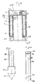
- la figure 1
- représente en coupe axiale longitudinale, un dispositif de projection pyrotechnique d'outils selon l'invention;
- la figure 2
- représente en coupe longitudinale à plus grande échelle, le sous-ensemble de chambre de combustion qui est associé au dispositif de projection pyrotechnique d'outil selon l'invention;
- la figure 3
- représente en vue éclatée, le sous-ensemble de chambre de combustion de la figure 2;
- la figure 4
- représente, en coupe axiale longitudinale, un autre mode de réalisation du dispositif de projection pyrotechnique d'outils selon l'invention, dans lequel un outil constitué par une tige-sonde coopère avec un système de mesure de vitesse de pénétration;
- la figure 5
- représente, en coupe axiale longitudinale, un autre mode de réalisation du dispositif de projection pyrotechnique d'outils selon l'invention, dans lequel un tube de réduction de calibre est monté à l'intérieur du tube de lancement;
- la figure 6
- représente une coupe à 90° du mode de réalisation de la figure 4;
- la figure 7,
- représente en coupe transversale, un autre mode de réalisation du générateur de gaz susceptible d'être utilisé dans le dispositif de projection pyrotechnique selon l'invention;
- la figure 8
- représente, en coupe axiale longitudinale, un autre mode de réalisation du dispositif de projection pyrotechnique d'outils selon l'invention, dans lequel l'outil peut être mis en place à l'aide d'un filin axial de chargement;
- les figures 9 à 13
- représentent divers modes de réalisation des outils susceptibles d'être associés au dispositif de projection pyrotechnique selon l'invention; et
- la figure 14
- représente en élévation un véhicule chenillé de transport et de mise en place d'un système de projection d'outils utilisant le dispositif de projection pyrotechnique selon l'invention.
Claims (7)
- Dispositif de projection pyrotechnique d'un outil relié à un piston de projection (41) mobile à l'intérieur d'un tube de lancement (5), caractérisé en ce qu'il est contenu dans un fût ou bâti (1) et est constitué d'un générateur de gaz de projection (9), associé à un système de déclenchement (9a), placé dans une culasse (7) fixée à une extrémité d'un tube de lancement (5) solidaire d'une masse lest (3) qui est destinée à supporter l'effet de recul exercé sur la culasse (7) au cours de la projection et qui est reliée à l'une de ses extrémités à un vérin amortisseur (6) interposé entre le bâti (1) et la masse lest (3) pour amortir la retombée de cette masse lest après son recul.
- Dispositif de projection pyrotechnique d'un outil selon la revendication 1, caractérisé en ce que le générateur de gaz (9) et son système de déclenchement (9a) forment un sous-ensemble fixé extérieurement et de façon aisément amovible à la culasse (7) à une extrémité du tube de lancement (5) qui reçoit l'outil à travers l'autre extrémité.
- Dispositif de projection pyrotechnique d'un outil selon l'une quelconque des revendications 1 ou 2, caractérisé en ce que le tube de lancement (5) comporte, à son extrémité opposée au générateur de gaz (9), des évents latéraux (17) d'éjection des gaz avant la sortie du piston de projection (41) hors du tube de lancement (5) et en ce que ces évents débouchent dans une chambre annulaire (1a) ménagée entre la paroi extérieure du tube de lancement (5) et un prolongement cylindrique (1a) du bâti (1) entourant le tube de lancement (5).
- Dispositif de projection pyrotechnique d'un outil selon l'une quelconque des revendications 1 à 3, caractérisé en ce que le tube de lancement (5) est équipé intérieurement d'un tube sous-calibré gigogne (21) permettant l'emploi d'un piston (41) de projection d'outils de plus petit diamètre.
- Dispositif de projection pyrotechnique d'un outil selon l'une quelconque des revendications 1 à 4, caractérisé en ce que le système de déclenchement (9a) fonctionne par percussion d'une amorce (28) d'un générateur de gaz d'allumage et est séparé de la culasse (7) recevant le générateur de gaz de projection (9) et isolé par une pièce à évents (75) apte à éjecter les gaz du système de déclenchement.
- Dispositif de projection pyrotechnique d'un outil selon l'une quelconque des revendications 1 à 5, caractérisé en ce qu'il comporte un organe de chargement constitué d'un câble (22) traversant axialement le tube de lancement (5) et relié à une pince de préhension (23) susceptible d'être déconnectée sous l'effet de la force de propulsion agissant sur le piston (41) de projection de l'outil dans le tube de lancement (5) et d'une plaque d'étanchéité (24) servant d'élément d'appui et de butée lors de la remontée de l'outil dans le tube de lancement (5) et à la commande de la libération de la pince (23).
- Dispositif de projection pyrotechnique d'un outil selon l'une quelconque des revendications 1 à 6, caractérisé en ce que l'outil peut être entre autres un outil tel que compacteur à plateau (45), compacteur à poinçon (49), tube de carottage (53), tube d'enfouissement (59), injecteur (37), pénétromètre (43), tige porteuse de câble de terre (33).
Applications Claiming Priority (3)
| Application Number | Priority Date | Filing Date | Title |
|---|---|---|---|
| FR9409340A FR2723115B1 (fr) | 1994-07-26 | 1994-07-26 | Projeteur pyrotechnique d'outils |
| FR9409340 | 1994-07-26 | ||
| PCT/FR1995/000998 WO1996003549A1 (fr) | 1994-07-26 | 1995-07-25 | Dispositif de projection pyrotechnique d'outils |
Publications (2)
| Publication Number | Publication Date |
|---|---|
| EP0774025A1 EP0774025A1 (fr) | 1997-05-21 |
| EP0774025B1 true EP0774025B1 (fr) | 1998-12-23 |
Family
ID=9465830
Family Applications (1)
| Application Number | Title | Priority Date | Filing Date |
|---|---|---|---|
| EP95926425A Expired - Lifetime EP0774025B1 (fr) | 1994-07-26 | 1995-07-25 | Dispositif de projection pyrotechnique d'outils |
Country Status (8)
| Country | Link |
|---|---|
| EP (1) | EP0774025B1 (fr) |
| AT (1) | ATE174985T1 (fr) |
| AU (1) | AU3082295A (fr) |
| CA (1) | CA2195803A1 (fr) |
| DE (1) | DE69506880T2 (fr) |
| ES (1) | ES2128751T3 (fr) |
| FR (1) | FR2723115B1 (fr) |
| WO (1) | WO1996003549A1 (fr) |
Cited By (1)
| Publication number | Priority date | Publication date | Assignee | Title |
|---|---|---|---|---|
| CN101443646B (zh) * | 2006-05-16 | 2012-10-10 | 朗讯科技公司 | 冲击和发射设备 |
Family Cites Families (3)
| Publication number | Priority date | Publication date | Assignee | Title |
|---|---|---|---|---|
| FR2407296A1 (fr) * | 1977-10-27 | 1979-05-25 | Rech Etudes Tech | Procede et dispositif de realisation de trous verticaux dans le sol, notamment en vue du plantage ulterieur de poteaux, piquets ou analogues |
| DE3167401D1 (en) * | 1980-05-05 | 1985-01-10 | Travocean Sarl | Pyrotechnic device for anchoring piles or similar objects in the soil |
| FR2644811B1 (fr) * | 1989-03-23 | 1991-05-24 | Castagner Bernard | Systeme pyrotechnique destine a enfoncer des ancrages dans le sol |
-
1994
- 1994-07-26 FR FR9409340A patent/FR2723115B1/fr not_active Expired - Fee Related
-
1995
- 1995-07-25 CA CA002195803A patent/CA2195803A1/fr not_active Abandoned
- 1995-07-25 AT AT95926425T patent/ATE174985T1/de active
- 1995-07-25 AU AU30822/95A patent/AU3082295A/en not_active Abandoned
- 1995-07-25 WO PCT/FR1995/000998 patent/WO1996003549A1/fr not_active Ceased
- 1995-07-25 ES ES95926425T patent/ES2128751T3/es not_active Expired - Lifetime
- 1995-07-25 DE DE69506880T patent/DE69506880T2/de not_active Expired - Fee Related
- 1995-07-25 EP EP95926425A patent/EP0774025B1/fr not_active Expired - Lifetime
Cited By (1)
| Publication number | Priority date | Publication date | Assignee | Title |
|---|---|---|---|---|
| CN101443646B (zh) * | 2006-05-16 | 2012-10-10 | 朗讯科技公司 | 冲击和发射设备 |
Also Published As
| Publication number | Publication date |
|---|---|
| FR2723115A1 (fr) | 1996-02-02 |
| EP0774025A1 (fr) | 1997-05-21 |
| FR2723115B1 (fr) | 1996-12-06 |
| ATE174985T1 (de) | 1999-01-15 |
| AU3082295A (en) | 1996-02-22 |
| DE69506880D1 (de) | 1999-02-04 |
| CA2195803A1 (fr) | 1996-02-08 |
| ES2128751T3 (es) | 1999-05-16 |
| DE69506880T2 (de) | 1999-08-19 |
| WO1996003549A1 (fr) | 1996-02-08 |
Similar Documents
| Publication | Publication Date | Title |
|---|---|---|
| EP0389375B1 (fr) | Système d'enfoncement d'ancrage dans un sol | |
| EP0151060B1 (fr) | Dispositif pour engendrer des impulsions acoustiques à l'intérieur d'un puits, par percussion | |
| EP0334752B1 (fr) | Dispositif perfectionné pour engendrer des ondes acoustiques par percussion d'une masse chutant sur un élément-cible couplé avec les parois d'un puits | |
| CA1054808A (fr) | Dispositif pour enterrer des elements flexibles de grande longueur | |
| EP0039654B1 (fr) | Dispositif pyrotechnique pour ancrer dans le sol des pieux ou autres objets similaires | |
| EP0774025B1 (fr) | Dispositif de projection pyrotechnique d'outils | |
| FR2472195A1 (fr) | Appareil de generation d'impulsion acoustique dans un milieu | |
| WO2002096517A1 (fr) | Dispositif pour exercer une poussee sur une porte ou toute autre surface plane verticale | |
| EP0136236B1 (fr) | Dispositif pour engendrer des impulsions sismiques à l'intérieur d'un forage, par chute d'une masse sur un élément-cible ancré | |
| CA1033048A (fr) | Dispositif pour l'emission d'ondes acoustiques par implosion | |
| CA1318846C (fr) | Accumulation de l'energie en un point d'un puits de forage par traction d'une colonne | |
| EP0308321A1 (fr) | Appareil de scellement pour travaux sous-marins | |
| FR2492088A1 (fr) | Simulateur d'entrainement au chargement d'un canon | |
| FR2519132A1 (fr) | Dispositif d'alimentation d'une arme en munitions | |
| EP0262037B1 (fr) | Dispositif d'éjection au moyen d'une charge propulsive liquide d'un projectile placé dans un tube de lancement | |
| US5913252A (en) | Pyrotechnic tool driving device | |
| EP0018870B1 (fr) | Appareil de scellement à masselotte | |
| CN116356796B (zh) | 一种滩涂地区远程静音地基快速冰冻固化处理装置 | |
| FR2757443A1 (fr) | Procede et dispositif de compactage de matieres compressibles, en particulier de dechets | |
| FR2678073A1 (fr) | Source d'ondes elastiques a percussion pour puits. | |
| FR2714158A1 (fr) | Dispositif de récupération d'étuis de munitions. | |
| EP4696977A1 (fr) | Dispositif de déclenchement d'avalanches | |
| FR2461229A1 (fr) | Dispositif d'entrainement pour culasse de canon deplacable transversalement a l'axe de l'ame | |
| FR2986611A1 (fr) | Dispositif de lancement pneumatique | |
| FR2829585A1 (fr) | Impacteur d'etude sismique a percussion |
Legal Events
| Date | Code | Title | Description |
|---|---|---|---|
| PUAI | Public reference made under article 153(3) epc to a published international application that has entered the european phase |
Free format text: ORIGINAL CODE: 0009012 |
|
| 17P | Request for examination filed |
Effective date: 19970226 |
|
| AK | Designated contracting states |
Kind code of ref document: A1 Designated state(s): AT BE CH DE DK ES FR GB GR IE IT LI LU MC NL PT SE |
|
| GRAG | Despatch of communication of intention to grant |
Free format text: ORIGINAL CODE: EPIDOS AGRA |
|
| 17Q | First examination report despatched |
Effective date: 19971117 |
|
| GRAG | Despatch of communication of intention to grant |
Free format text: ORIGINAL CODE: EPIDOS AGRA |
|
| GRAH | Despatch of communication of intention to grant a patent |
Free format text: ORIGINAL CODE: EPIDOS IGRA |
|
| GRAH | Despatch of communication of intention to grant a patent |
Free format text: ORIGINAL CODE: EPIDOS IGRA |
|
| GRAA | (expected) grant |
Free format text: ORIGINAL CODE: 0009210 |
|
| AK | Designated contracting states |
Kind code of ref document: B1 Designated state(s): AT BE CH DE DK ES FR GB GR IE IT LI LU MC NL PT SE |
|
| PG25 | Lapsed in a contracting state [announced via postgrant information from national office to epo] |
Ref country code: NL Free format text: LAPSE BECAUSE OF FAILURE TO SUBMIT A TRANSLATION OF THE DESCRIPTION OR TO PAY THE FEE WITHIN THE PRESCRIBED TIME-LIMIT Effective date: 19981223 Ref country code: GR Free format text: LAPSE BECAUSE OF NON-PAYMENT OF DUE FEES Effective date: 19981223 Ref country code: AT Free format text: LAPSE BECAUSE OF FAILURE TO SUBMIT A TRANSLATION OF THE DESCRIPTION OR TO PAY THE FEE WITHIN THE PRESCRIBED TIME-LIMIT Effective date: 19981223 |
|
| REF | Corresponds to: |
Ref document number: 174985 Country of ref document: AT Date of ref document: 19990115 Kind code of ref document: T |
|
| REG | Reference to a national code |
Ref country code: CH Ref legal event code: EP |
|
| REF | Corresponds to: |
Ref document number: 69506880 Country of ref document: DE Date of ref document: 19990204 |
|
| REG | Reference to a national code |
Ref country code: IE Ref legal event code: FG4D Free format text: FRENCH |
|
| REG | Reference to a national code |
Ref country code: CH Ref legal event code: NV Representative=s name: PATMED AG |
|
| GBT | Gb: translation of ep patent filed (gb section 77(6)(a)/1977) |
Effective date: 19990203 |
|
| ITF | It: translation for a ep patent filed | ||
| PG25 | Lapsed in a contracting state [announced via postgrant information from national office to epo] |
Ref country code: SE Free format text: LAPSE BECAUSE OF FAILURE TO SUBMIT A TRANSLATION OF THE DESCRIPTION OR TO PAY THE FEE WITHIN THE PRESCRIBED TIME-LIMIT Effective date: 19990323 Ref country code: PT Free format text: LAPSE BECAUSE OF FAILURE TO SUBMIT A TRANSLATION OF THE DESCRIPTION OR TO PAY THE FEE WITHIN THE PRESCRIBED TIME-LIMIT Effective date: 19990323 Ref country code: DK Free format text: LAPSE BECAUSE OF FAILURE TO SUBMIT A TRANSLATION OF THE DESCRIPTION OR TO PAY THE FEE WITHIN THE PRESCRIBED TIME-LIMIT Effective date: 19990323 |
|
| REG | Reference to a national code |
Ref country code: ES Ref legal event code: FG2A Ref document number: 2128751 Country of ref document: ES Kind code of ref document: T3 |
|
| NLV1 | Nl: lapsed or annulled due to failure to fulfill the requirements of art. 29p and 29m of the patents act | ||
| PG25 | Lapsed in a contracting state [announced via postgrant information from national office to epo] |
Ref country code: LU Free format text: LAPSE BECAUSE OF NON-PAYMENT OF DUE FEES Effective date: 19990725 Ref country code: IE Free format text: LAPSE BECAUSE OF NON-PAYMENT OF DUE FEES Effective date: 19990725 Ref country code: GB Free format text: LAPSE BECAUSE OF NON-PAYMENT OF DUE FEES Effective date: 19990725 |
|
| PG25 | Lapsed in a contracting state [announced via postgrant information from national office to epo] |
Ref country code: ES Free format text: LAPSE BECAUSE OF NON-PAYMENT OF DUE FEES Effective date: 19990726 |
|
| PG25 | Lapsed in a contracting state [announced via postgrant information from national office to epo] |
Ref country code: LI Free format text: LAPSE BECAUSE OF NON-PAYMENT OF DUE FEES Effective date: 19990731 Ref country code: CH Free format text: LAPSE BECAUSE OF NON-PAYMENT OF DUE FEES Effective date: 19990731 |
|
| PLBE | No opposition filed within time limit |
Free format text: ORIGINAL CODE: 0009261 |
|
| STAA | Information on the status of an ep patent application or granted ep patent |
Free format text: STATUS: NO OPPOSITION FILED WITHIN TIME LIMIT |
|
| 26N | No opposition filed | ||
| PG25 | Lapsed in a contracting state [announced via postgrant information from national office to epo] |
Ref country code: MC Free format text: LAPSE BECAUSE OF NON-PAYMENT OF DUE FEES Effective date: 20000131 |
|
| GBPC | Gb: european patent ceased through non-payment of renewal fee |
Effective date: 19990725 |
|
| REG | Reference to a national code |
Ref country code: CH Ref legal event code: PL |
|
| REG | Reference to a national code |
Ref country code: IE Ref legal event code: MM4A |
|
| PGFP | Annual fee paid to national office [announced via postgrant information from national office to epo] |
Ref country code: DE Payment date: 20000615 Year of fee payment: 7 |
|
| PGFP | Annual fee paid to national office [announced via postgrant information from national office to epo] |
Ref country code: FR Payment date: 20010126 Year of fee payment: 6 Ref country code: BE Payment date: 20010126 Year of fee payment: 6 |
|
| PG25 | Lapsed in a contracting state [announced via postgrant information from national office to epo] |
Ref country code: BE Free format text: LAPSE BECAUSE OF NON-PAYMENT OF DUE FEES Effective date: 20010731 |
|
| BERE | Be: lapsed |
Owner name: CASTAGNER BERNARD Effective date: 20010731 |
|
| PG25 | Lapsed in a contracting state [announced via postgrant information from national office to epo] |
Ref country code: FR Free format text: LAPSE BECAUSE OF NON-PAYMENT OF DUE FEES Effective date: 20020329 |
|
| REG | Reference to a national code |
Ref country code: FR Ref legal event code: ST |
|
| PG25 | Lapsed in a contracting state [announced via postgrant information from national office to epo] |
Ref country code: DE Free format text: LAPSE BECAUSE OF NON-PAYMENT OF DUE FEES Effective date: 20030201 |
|
| REG | Reference to a national code |
Ref country code: ES Ref legal event code: FD2A Effective date: 20000810 |
|
| PG25 | Lapsed in a contracting state [announced via postgrant information from national office to epo] |
Ref country code: IT Free format text: LAPSE BECAUSE OF NON-PAYMENT OF DUE FEES;WARNING: LAPSES OF ITALIAN PATENTS WITH EFFECTIVE DATE BEFORE 2007 MAY HAVE OCCURRED AT ANY TIME BEFORE 2007. THE CORRECT EFFECTIVE DATE MAY BE DIFFERENT FROM THE ONE RECORDED. Effective date: 20050725 |