EP0774077B1 - Pompe a circulation destinee a amener du carburant d'un reservoir au moteur a combustion interne d'un vehicule - Google Patents
Pompe a circulation destinee a amener du carburant d'un reservoir au moteur a combustion interne d'un vehicule Download PDFInfo
- Publication number
- EP0774077B1 EP0774077B1 EP96900265A EP96900265A EP0774077B1 EP 0774077 B1 EP0774077 B1 EP 0774077B1 EP 96900265 A EP96900265 A EP 96900265A EP 96900265 A EP96900265 A EP 96900265A EP 0774077 B1 EP0774077 B1 EP 0774077B1
- Authority
- EP
- European Patent Office
- Prior art keywords
- impeller
- blades
- rotation
- axis
- flow pump
- Prior art date
- Legal status (The legal status is an assumption and is not a legal conclusion. Google has not performed a legal analysis and makes no representation as to the accuracy of the status listed.)
- Expired - Lifetime
Links
- 239000000446 fuel Substances 0.000 title claims description 13
- 238000005086 pumping Methods 0.000 title description 2
- 238000002485 combustion reaction Methods 0.000 claims description 4
- 238000010276 construction Methods 0.000 claims 1
- 230000015572 biosynthetic process Effects 0.000 description 3
- 230000002093 peripheral effect Effects 0.000 description 3
- 230000001419 dependent effect Effects 0.000 description 1
- 238000011161 development Methods 0.000 description 1
- 230000018109 developmental process Effects 0.000 description 1
- 239000012530 fluid Substances 0.000 description 1
- 239000002828 fuel tank Substances 0.000 description 1
- 230000035939 shock Effects 0.000 description 1
Images

Classifications
-
- F—MECHANICAL ENGINEERING; LIGHTING; HEATING; WEAPONS; BLASTING
- F04—POSITIVE - DISPLACEMENT MACHINES FOR LIQUIDS; PUMPS FOR LIQUIDS OR ELASTIC FLUIDS
- F04D—NON-POSITIVE-DISPLACEMENT PUMPS
- F04D5/00—Pumps with circumferential or transverse flow
-
- F—MECHANICAL ENGINEERING; LIGHTING; HEATING; WEAPONS; BLASTING
- F04—POSITIVE - DISPLACEMENT MACHINES FOR LIQUIDS; PUMPS FOR LIQUIDS OR ELASTIC FLUIDS
- F04D—NON-POSITIVE-DISPLACEMENT PUMPS
- F04D5/00—Pumps with circumferential or transverse flow
- F04D5/002—Regenerative pumps
-
- F—MECHANICAL ENGINEERING; LIGHTING; HEATING; WEAPONS; BLASTING
- F04—POSITIVE - DISPLACEMENT MACHINES FOR LIQUIDS; PUMPS FOR LIQUIDS OR ELASTIC FLUIDS
- F04D—NON-POSITIVE-DISPLACEMENT PUMPS
- F04D29/00—Details, component parts, or accessories
- F04D29/18—Rotors
- F04D29/188—Rotors specially for regenerative pumps
Definitions
- the invention relates to a flow pump for conveying Fuel from a reservoir to the internal combustion engine of a motor vehicle according to the preamble of claim 1.
- Such a flow pump is known from WO-A-92 00457.
- This flow pump has a rotating one in a pump chamber Impeller on at least one axially directed Front a ring of circumferentially at a distance has wings arranged to each other.
- the impeller with the Wing ring acts with an annular conveyor channel for conveying of the fuel together.
- the wings are in contemplation radial direction with respect to the axis of rotation of the impeller parallel arranged to the axis of rotation of the impeller. Because of this arrangement the wing is not optimal in the known flow pump Delivery pressure and efficiency achieved.
- a flow pump is known from US-A-1 689 579, at the impeller rotating in a pump chamber on its Frontal wreaths of wings with a annular conveyor channel for conveying a medium work together.
- the blades of the impeller are radial Consideration of the axis of rotation of the impeller in relation to the Axis of rotation so inclined that it to the front of the Run ahead of the impeller in the direction of rotation of the impeller.
- DE-A-1 403 575 is also a flow pump known in which the rotating impeller in a pump chamber its front sides has wreaths of wings, which with a annular conveyor channel for conveying a medium work together.
- the blades of the impeller are radial Consideration of the axis of rotation of the impeller in relation to the Axis of rotation so inclined that it to the front of the Run ahead of the impeller in the direction of rotation of the impeller.
- the flow pump according to the invention with the features according to Claim 1 has the advantage that the Formation of the wings with their radially outer ends opposite their radially inner ends in the circumferential direction of the Run ahead of the impeller, the delivery pressure and the efficiency are further improved.
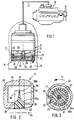
- FIG. 1 shows a flow pump for delivering fuel from a reservoir to the internal combustion engine Motor vehicle in a simplified representation
- Figure 2 in Enlarged representation of a designated II in Figure 1 Section of the flow pump according to a first Embodiment
- Figure 3 shows the impeller of the flow pump Figure 2 in a cross section perpendicular to its axis of rotation considered
- Figure 4 shows the impeller of the flow pump in one Section along line IV-IV in Figure 3
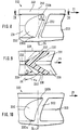
- Figure 5 the in Figure 1 II marked section of the flow pump according to a second embodiment
- Figure 6 the impeller Flow pump of Figure 5 in a cross section perpendicular to considered the axis of rotation
- Figure 7 shows the impeller Flow pump in a section along line VII-VII in Figure 6, FIG.
- FIG. 8 the impeller of the flow pump according to a first Embodiment in a side view in the direction of viewed its axis of rotation
- Figure 9 shows the impeller in one Section along line IX-IX in Figure 8
- Figure 10 a modified version of the impeller of Figure 8
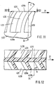
- Figure 11 das Impeller of the flow pump according to a second Embodiment in a side view in the direction of considered its axis of rotation
- Figure 12 the impeller in one Section along line XII-XII in Figure 11.
- FIGS. 1-7 a generic flow pump described.
- Figures 1-7 do not represent an embodiment of the invention.
- FIG. 1 shows a simplified representation of an aggregate 10, the in a common housing 12 a flow pump 14 and a Drive motor 15 for the flow pump 14 includes.
- the aggregate 10 is one in a fuel tank 16 Motor vehicle arranged and the flow pump 14 sucks during the operation of the unit 10 fuel from the Storage container 16 and conveys this via a pressure line 17 to the internal combustion engine 18 of the motor vehicle.
- the Flow pump 14 has a rotating one in a pump chamber 20 Impeller 22, with the pump chamber 20 in the direction of Axis of rotation 24 of the impeller 22 through a chamber wall 25, 26 in each case is limited.
- the flow pump 14 is shown in FIGS. 2 to 4 excerpts according to a first embodiment shown on the basis of which the structure as a so-called peripheral side channel pump is explained.
- the impeller 22 has at its two axially, that is called end faces directed in the direction of its axis of rotation 24 28, 29 each have a ring in the circumferential direction of the impeller 22 wings 30 arranged at a distance from one another. Between Wings 30 are each groove-like spaces 31 and the wings 30 are essentially flat. The reason of the groove-like intermediate spaces 31 is the axis of rotation 24 containing longitudinal sections viewed through the impeller 22 rounded, for example in the form of a Circular section.
- the wings 30 extend radially Direction with respect to the axis of rotation 24 of the impeller 22 from one radially inner end 30a to a radially outer end 30b on Outer periphery of the impeller 22.
- the wing rings of the two end faces 28, 29 approximately in the middle the axial width of the impeller 22 separating web 33 up to the end faces 28, 29 of the impeller 22.
- the wing rings of the impeller 22 act with one in the Pump chamber 20 formed annular delivery channel 34 for Pumping fuel together. Open into the delivery channel 34 the beginning of which has a suction opening 35 and at the end of which one Pressure port 36. The fuel to be pumped flows through the Suction opening 35 into the delivery channel 34 and flows out of this under increased pressure through the pressure opening 36.
- the Delivery channel 34 extends in the radial direction with respect to Axis of rotation 24 of the impeller 22 starting from the radially inner Ends 30a of the wings 30 to beyond their radially outer ends 30b out. Extends in the direction of the axis of rotation 24 of the impeller 22 the delivery channel 34 each over the end faces 28, 29 of the Impeller 22 addition.
- the delivery channel 34 is thus in the direction of Axis of rotation 24 of the impeller 22 laterally next to the blades 30 arranged and also extends over the outer circumference of the Impeller 22.
- the wings 30 are so inclined placed arranged that this starting from the web 33 to respective end faces 28, 29 at which the wings 30 end, Lead ahead in the direction of rotation 21 of the impeller 22.
- the wing 30 is not parallel to the axis of rotation 24 of the impeller 22 are arranged, that is at right angles to the respective end face 28, 29, but with the axis of rotation 24 one in the circumferential direction 21 of the impeller 22 include directed angle ⁇ .
- the angle ⁇ is between 25 ° and 60 °, preferably between 30 ° and 55 °. Due to this inclination of the wings 30, these are approximately parallel to that indicated by the arrows 40 in FIG.
- the flow pump 14 is according to one shown second embodiment, based on which the structure as a so-called Side channel pump is explained.
- the impeller 122 instructs its two axially directed end faces 128, 129 each a ring in the circumferential direction of the impeller 122 at a distance wings 130 arranged to each other, between each of which groove-like spaces 131 are present.
- the wings 130 of the two end faces 128, 129 of the impeller 122 are through one Web 133 in the direction of the axis of rotation 24 of the impeller 122 viewed separately from each other and are at their radially outer Ends 130b together by a closed ring 140 connected.
- the web 133 can in the radial direction with respect to the The axis of rotation 24 of the impeller 122 must be continuous, so that the two end faces 128, 129 of the impeller 122 completely are separated from one another, or the web 133 can be radial Direction end in front of the ring 140, so that between web 133 and Ring 140 in the area of the spaces 131 each have an opening 142 remains through which the two end faces 128, 129 of the Impeller 122 are connected.
- Chamber walls 125, 126 are each an annular delivery channel 144 and 145 are formed, the delivery channels 144, 145 the respective wreath of wings 130 in the end faces 128, 129 of the Impeller 122 are formed opposite.
- Delivery channel 144 opens at the beginning of the suction opening 135 and in the other conveyor channel 145 opens at the end of the Pressure opening 136.
- the two delivery channels 144, 145 have the outer circumference of the impeller 122, that is, over the outer circumference of the ring 140 no connection with each other.
- the wings 130 are as described in the first embodiment according to FIG 7 arranged so inclined that they start from Web 133 to the respective end face 128, 129, on which the Blade 130 ends, in the direction of rotation 21 of the impeller 122 hurry ahead.
- the angle ⁇ is between 25 ° and 60 °, preferably between 30 ° and 55 °.
- the impeller 222 is the flow pump 14 shown according to a first embodiment.
- the Flow pump 14 is like the second embodiment designed as a side channel pump and there are the two in figure 5 visible delivery channels available, each with the Wing ring of an end face of the impeller 222 with a Conveyor channel interacts.
- the impeller 222 points to its two axially directed end faces 228, 229 each have a ring of spaced apart in the circumferential direction Wings 230, between each of which groove-like spaces 23i are present, the base of which is rounded, for example in the form a circular section is formed.
- the wings 230 are on their radially outer ends 230b with one another via a ring 240 connected.
- edges 232 of the wings 230 with which these do not end at the respective end face 228, 229 of the impeller arranged radially with respect to the axis of rotation 24 of the impeller 222, rather, the edges 232 run at the radially outer ends 230b the wing 230 opposite its arrangement on the radially inner Ends 230a of the blades 230 in the circumferential direction 21 of the impeller 222 ahead.
- the edges 232 of the wings 230 on the respective Front side 228, 229 of the impeller 222 extend from the radially inner ends 230a of wings 230 to the radially outer ones Ends 230b of the wings 230 rectilinear.
- the wings 230 are also arranged so that they start in the circumferential direction from the web 233 separating the wings 230 of the two end faces 228, 229 from one another to the respective end face 228, 229 at which the wings 230 end Lead ahead 21 of impeller 222.
- the vanes 230 are not arranged parallel to the axis of rotation 24 of the impeller 222, but instead form an angle ⁇ directed in the direction of rotation 21 of the impeller 222 with the axis of rotation 24.
- the angle ⁇ is not constant over the course of the vanes 230 starting from their radially inner end 230a to their radially outer end 230b.
- the vanes 230 on the respective end face 228, 229 of the impeller 222 with the axis of rotation 24 form an angle ⁇ E directed in the circumferential direction 21 of the impeller 222, which is between 25 ° and 50 °, in particular between 30 ° and 45 ° is.
- the angle ⁇ E is preferably approximately 37 °.
- the vanes 230 on the respective end face 228, 229 of the impeller 222 with the axis of rotation 24 form an angle ⁇ A directed in the circumferential direction 21 of the impeller 222, which is between 45 ° and 70 °, in particular between 50 ° and 65 °.
- the angle ⁇ A is preferably approximately 60 °. Starting from the radially inner ends 230a of the vanes 230, the angle ⁇ increases linearly towards their radially outer ends 230b. This increase in the angle ⁇ starting from the radially inner ends 230a of the vanes 230 to their radially outer ends 230b results in the above-described arrangement of the edges 232 of the vanes 230 in the circumferential direction 21 of the impeller 222 by the angle ⁇
- the inner ends of web 233 are arranged in the cross section perpendicular to the axis of rotation 24 of the impeller 222, viewed approximately radially with respect to the axis of rotation 24, and are therefore not inclined as on their edge 232 located on the end face.
- FIG. 10 shows a variant of the impeller 322 Flow pump according to the first embodiment in one Side view shown.
- the impeller 322 is in the essentially the same as the first Embodiment, however, runs the edge 332 with which the Vane 330 does not end at the front of impeller 322 straight but curved.
- edge 332 is approximately radial with respect to FIG Axis of rotation 24 of the impeller 322 and the edge 332 extends to the radially outer ends 330b of the wings 330 continuously increasing in the direction of rotation 21 of the impeller 322.
- the angle ⁇ is the wing 330 with the Include axis of rotation 24 of the impeller 322 starting from the radially inner ends 330a of the wings 330 to their radially outer ends Ends 330b larger.
- the increase in the size of the angle ⁇ is not linear as in the first embodiment but reinforces to the radially outer ends 330b of FIG Wing 330 back.
- the inner ends of the wings 330 are perpendicular in cross section viewed approximately radially to the axis of rotation 24 of the impeller 322 with respect to the axis of rotation 24, so they are not as at their on Front edge 332 curved.
- the impeller 422 is the flow pump 14 according to a second embodiment.
- the Flow pump 14 is a peripheral side channel pump trained and has a conveyor channel as in the first Embodiment shown in Figure 2.
- the impeller 422 has 428,429 on its two axially directed end faces in each case a wreath at a distance in the circumferential direction wings 430 arranged to each other, between each of which Spaces 431 are present.
- the wings 430 extend in the radial direction with respect to the axis of rotation 24 of the impeller 422 from a radially inner end 430a to a radially outer end End 430b on the outer circumference of the impeller 422.
- the axes of rotation 24 of the impeller 422 extend the blades 430 starting from one the wreaths of the two faces 428,429 approximately in the middle of the axial width of the impeller 422 separating web 433 up to the end faces 428,429 of the impeller 422.
- the vanes 430 are as in the above described embodiments so inclined arranged that these starting from the web 433 to the respective End face 428,429, on which the wings 430 end, in Lead ahead in the direction of rotation 21 of the impeller 422. This means, that the wing 430 is not parallel to the axis of rotation 24 of the impeller 422 are arranged, but with the axis of rotation 24 one in Direction of rotation 21 of the impeller 422 directed angle ⁇ lock in.
- the angle ⁇ is between 25 ° and 50 °, especially between 30 ° and 45 °.
- The is preferably Angle ⁇ about 37 °.
- the angle ⁇ is over the radial extent the wing 430, that is between its radially inner ends 430a and their radially outer ends 430b approximately constant.
- the wings 430 extend in the direction of the axis of rotation 24 of the impeller 422 viewed between their radially inner ends 430a and hers radially outer ends 430b curved, but can be at a other version also run in a straight line.
- the radially inner ends 430a initially run approximately 430 radially with respect to the axis of rotation 24 of the impeller 422 and to the latter radially outer ends 430b take the curvature, that is, the Deviation from the radial arrangement too.
- the wings 430 In the area of their radially outer ends 430b close the wings 430 with one Axis of rotation 24 of the impeller 422 radial line 450 through the the radially outer ends 430b of the wing 430 is placed one in Direction of rotation 21 directed angle ⁇ .
- the angle is ⁇ between 30 ° and 60 °, in particular between 40 ° and 55 °.
- the angle ⁇ is preferably approximately 45 °.
- the arrangement of the wings 430 is necessary because a peripheral side channel pump the fuel to be pumped like a side channel pump in the radial area inner ends 430a of wings 430 into spaces 431 enters, but exits radially outwards.
- the wings 430 are in cross section perpendicular to the axis of rotation 24 of the impeller 422 viewed in the area of its inner arranged on the web 433 Ends are also curved in the circumferential direction 21 as at the end faces 428, 429 of the impeller 422.
Landscapes
- Engineering & Computer Science (AREA)
- Mechanical Engineering (AREA)
- General Engineering & Computer Science (AREA)
- Structures Of Non-Positive Displacement Pumps (AREA)
- Rotary Pumps (AREA)
Claims (11)
- Pompe à circulation pour transférer du carburant dans un réservoir (16) d'un moteur à combustion interne (18) d'un véhicule automobile, comprenant,caractérisée en ce queun rotor (322, 422) tournant dans une chambre de pompe (20), ce rotor ayant au moins sur une face frontale (228, 229 ; 428, 429) dirigée axialement, une couronne d'ailettes (230, 330, 430) écartées dans la direction périphérique, ces ailettes coopérant avec un canal de transfert annulaire (34, 144, 145) pour transférer le carburant,vues dans la direction radiale par rapport à l'axe de rotation (24) du rotor (222, 322, 422) par rapport à l'axe de rotation (24) les ailettes (230, 330, 430) sont inclinées pour que par rapport à au moins une face frontale dirigée axialement (228, 229 428, 429) du rotor (222, 322, 422) elles soient en avance dans la direction de circulation (21) du rotor (222, 322, 422) et que sur au moins une face frontale dirigée axialement (228, 229 ; 428, 429) du rotor (222, 322, 422), les ailettes (230, 330, 430) soient en avance avec leur extrémité radiale extérieure (230b, 330b, 430b) par rapport à leur extrémité radiale intérieure (230a, 330a, 430a) dans la direction de circulation (21) du rotor (222, 322, 422).
- Pompe à circulation selon la revendication 1,
caractérisée en ce que
les ailettes (330, 430) forment avec l'axe de rotation (24) du rotor, un angle (α) dirigé dans la direction de circulation (21) du rotor, cet angle étant compris entre (25° et 70°). - Pompe à circulation selon la revendication 1,
caractérisée en ce que
les ailettes (230, 330) sur au moins une face frontale dirigée axialement (228, 229) du rotor (222, 322), partant de leur extrémité radiale intérieure (230a, 330a) sont inclinées par rapport à une disposition radiale théorique (250), dans la direction de circulation (21), d'un angle (β) compris entre 20° et 45°. - Pompe à circulation selon l'une des revendications précédentes,
caractérisée en ce que
l'angle (α) d'inclinaison des ailettes (230, 330) par rapport à l'axe de rotation (24) du rotor (222, 322) augmente à partir de l'extrémité radiale intérieure (230a, 330a) des ailettes (230, 330) vers leur extrémité radiale extérieure (230b, 330b) . - Pompe à circulation selon la revendication 4,
caractérisée en ce quedans la zone de leur extrémité radiale intérieure (230a, 330a), les ailettes (230) sont inclinées d'un angle (αE) par rapport à l'axe de rotation (24) du rotor (222), cet angle étant compris entre 25° et 50° et,dans la zone de leur extrémité radiale extérieure (230b, 330b) les ailettes (230) sont inclinées d'un angle (αA) par rapport à l'axe de rotation (24) du rotor (222), cet angle étant compris entre 45° et 70°. - Pompe à circulation selon l'une des revendications précédentes,
caractérisée en ce que
les ailettes sont essentiellement planes. - Pompe à circulation selon l'une des revendications 1 à 5,
caractérisée en ce que
les ailettes (330, 430) sont courbées à partir de leur extrémité radiale intérieure (330a, 430a) vers leur extrémité radiale extérieure (330b, 430b) dans la direction de circulation (21) du rotor (322, 422). - Pompe à circulation selon la revendication 7,
caractérisée en ce que
les ailettes (330, 430) sont sensiblement radiales par rapport à l'axe de rotation (24) du rotor (322, 422) dans la zone de leur extrémité radiale intérieure (330a, 430a). - Pompe à circulation selon l'une des revendications précédentes,
caractérisée en ce queles extrémités radiales extérieures (230b, 330b) des ailettes (230, 330) sont reliées par un anneau fermé (240) et,le canal de transfert annulaire (145, 146) est réalisé dans une paroi (125, 126) qui délimite la chambre de pompe (20) dans la direction de l'axe de rotation (24) du rotor (222, 322) et ce canal s'étend dans la direction radiale par rapport à l'axe de rotation (24) entre l'extrémité radiale intérieure (230a, 330a) et l'extrémité radiale extérieure (230b, 330b) des ailettes (230, 330). - Pompe à circulation selon l'une des revendications 1 à 8,
caractérisée en ce qu'
au niveau de ses deux faces frontales axiales (28, 29), le rotor (422) comporte chaque fois une couronne d'ailettes (430) et le canal de transfert (34) s'étend des deux côtés des faces frontales (28, 29) du rotor (422) et sur sa périphérie extérieure. - Pompe à circulation selon la revendication 10,
caractérisée en ce que
les ailettes (430) du rotor (422) font avec l'axe de rotation (24) du rotor, un angle (a) dirigé dans la direction périphérique (21) du rotor, cet angle étant compris entre 25° et 50°, et en coupe perpendiculaire à l'axe de rotation (24), les ailettes (430) considérées dans la zone de leur extrémité radiale extérieure (430b) sont en avance par rapport à une disposition radiale (450) par rapport à l'axe de rotation (24) d'un angle (γ) dans la direction de circulation (21) du rotor (422), cet angle (γ) étant compris entre (30° et 60°).
Applications Claiming Priority (3)
| Application Number | Priority Date | Filing Date | Title |
|---|---|---|---|
| DE19504079 | 1995-02-08 | ||
| DE19504079A DE19504079B4 (de) | 1995-02-08 | 1995-02-08 | Strömungspumpe zum Fördern von Kraftstoff aus einem Vorratsbehälter zur Brennkraftmaschine eines Kraftfahrzeugs |
| PCT/DE1996/000024 WO1996024769A1 (fr) | 1995-02-08 | 1996-01-10 | Pompe a circulation destinee a amener du carburant d'un reservoir au moteur a combustion interne d'un vehicule |
Publications (3)
| Publication Number | Publication Date |
|---|---|
| EP0774077A1 EP0774077A1 (fr) | 1997-05-21 |
| EP0774077B1 true EP0774077B1 (fr) | 2000-08-23 |
| EP0774077B2 EP0774077B2 (fr) | 2006-04-05 |
Family
ID=7753421
Family Applications (1)
| Application Number | Title | Priority Date | Filing Date |
|---|---|---|---|
| EP96900265A Expired - Lifetime EP0774077B2 (fr) | 1995-02-08 | 1996-01-10 | Pompe a circulation destinee a amener du carburant d'un reservoir au moteur a combustion interne d'un vehicule |
Country Status (8)
| Country | Link |
|---|---|
| US (1) | US5807068A (fr) |
| EP (1) | EP0774077B2 (fr) |
| JP (1) | JPH09511812A (fr) |
| KR (1) | KR100382681B1 (fr) |
| CN (1) | CN1071420C (fr) |
| BR (1) | BR9605117A (fr) |
| DE (2) | DE19504079B4 (fr) |
| WO (1) | WO1996024769A1 (fr) |
Families Citing this family (33)
| Publication number | Priority date | Publication date | Assignee | Title |
|---|---|---|---|---|
| DE19615322A1 (de) * | 1996-04-18 | 1997-10-23 | Vdo Schindling | Peripheralpumpe |
| DE19615323A1 (de) * | 1996-04-18 | 1997-10-23 | Vdo Schindling | Peripheralpumpe |
| US5762469A (en) * | 1996-10-16 | 1998-06-09 | Ford Motor Company | Impeller for a regenerative turbine fuel pump |
| DE19719609A1 (de) * | 1997-05-09 | 1998-11-12 | Bosch Gmbh Robert | Aggregat zum Fördern von Kraftstoff aus einem Vorratsbehälter zur Brennkraftmaschine eines Kraftfahrzeuges |
| US6224323B1 (en) | 1997-08-07 | 2001-05-01 | Aisan Kogyo Kabushiki Kaisha | Impeller of motor-driven fuel pump |
| DE19757580A1 (de) | 1997-12-23 | 1999-07-01 | Bosch Gmbh Robert | Seitenkanalpumpe mit Seitenkanal im Ansaugdeckel zur Vermeidung verlustbehafteter Wirbelstrukturen |
| JP3756337B2 (ja) | 1999-02-09 | 2006-03-15 | 愛三工業株式会社 | 流体ポンプ |
| US6113363A (en) * | 1999-02-17 | 2000-09-05 | Walbro Corporation | Turbine fuel pump |
| DE19912314C2 (de) * | 1999-03-19 | 2002-10-10 | Siemens Ag | Förderpumpe |
| US6296439B1 (en) * | 1999-06-23 | 2001-10-02 | Visteon Global Technologies, Inc. | Regenerative turbine pump impeller |
| US6299406B1 (en) * | 2000-03-13 | 2001-10-09 | Ford Global Technologies, Inc. | High efficiency and low noise fuel pump impeller |
| DE10013908A1 (de) * | 2000-03-21 | 2001-09-27 | Mannesmann Vdo Ag | Förderpumpe |
| US6527506B2 (en) * | 2000-03-28 | 2003-03-04 | Delphi Technologies, Inc. | Pump section for fuel pump |
| US6439833B1 (en) * | 2000-08-31 | 2002-08-27 | Delphi Technologies, Inc. | V-blade impeller design for a regenerative turbine |
| US6425733B1 (en) | 2000-09-11 | 2002-07-30 | Walbro Corporation | Turbine fuel pump |
| US6533538B2 (en) * | 2000-12-07 | 2003-03-18 | Delphi Technologies, Inc. | Impeller for fuel pump |
| JP4827319B2 (ja) | 2001-05-09 | 2011-11-30 | 株式会社ミツバ | 液体ポンプのインペラ |
| JP2003193991A (ja) * | 2001-12-25 | 2003-07-09 | Aisan Ind Co Ltd | 燃料ポンプ |
| JP3964200B2 (ja) * | 2001-12-26 | 2007-08-22 | 愛三工業株式会社 | 燃料ポンプ |
| DE10202366A1 (de) * | 2002-01-23 | 2003-08-07 | Pierburg Gmbh | Seitenkanalpumpe |
| US7037066B2 (en) | 2002-06-18 | 2006-05-02 | Ti Group Automotive Systems, L.L.C. | Turbine fuel pump impeller |
| US6932562B2 (en) * | 2002-06-18 | 2005-08-23 | Ti Group Automotive Systems, L.L.C. | Single stage, dual channel turbine fuel pump |
| JP4692009B2 (ja) * | 2004-04-07 | 2011-06-01 | 株式会社デンソー | 燃料ポンプ用インペラおよびそれを用いた燃料ポンプ |
| JP2006022727A (ja) * | 2004-07-08 | 2006-01-26 | Aisan Ind Co Ltd | 燃料噴射弁 |
| JP4252507B2 (ja) * | 2004-07-09 | 2009-04-08 | 愛三工業株式会社 | 燃料ポンプ |
| JP4912090B2 (ja) * | 2006-08-30 | 2012-04-04 | 愛三工業株式会社 | インペラ及びインペラを用いた燃料ポンプ |
| GB2477178B (en) | 2010-02-18 | 2012-01-11 | Quail Res And Design Ltd | Improved Pump |
| US9249806B2 (en) | 2011-02-04 | 2016-02-02 | Ti Group Automotive Systems, L.L.C. | Impeller and fluid pump |
| DE102013220668A1 (de) * | 2013-10-14 | 2015-04-16 | Continental Automotive Gmbh | Laufrad für eine insbesondere als Seitenkanalgebläse ausgebildete Seitenkanal-Strömungsmaschine |
| DE102013220717B4 (de) * | 2013-10-14 | 2016-04-07 | Continental Automotive Gmbh | Pumpe |
| KR101888056B1 (ko) * | 2014-11-03 | 2018-08-13 | 주식회사 코아비스 | 다단 연료펌프 |
| DE102017215731A1 (de) | 2017-09-07 | 2019-03-07 | Robert Bosch Gmbh | Seitenkanalverdichter für ein Brennstoffzellensystem zur Förderung und/oder Verdichtung von einem gasförmigen Medium |
| US12000411B2 (en) | 2022-01-07 | 2024-06-04 | Phinia Delphi Luxembourg Sarl | Fluid pump impeller including blades extending from a hub to an outer ring and having a draft angle between adjacent blades that varies between the hub and the outer ring |
Citations (3)
| Publication number | Priority date | Publication date | Assignee | Title |
|---|---|---|---|---|
| US2042499A (en) * | 1933-09-15 | 1936-06-02 | Roots Connersville Blower Corp | Rotary pump |
| US2217211A (en) * | 1937-09-11 | 1940-10-08 | Roots Connersville Blower Corp | Rotary pump |
| US3095820A (en) * | 1960-02-29 | 1963-07-02 | Mcculloch Corp | Reentry rotary fluid pump |
Family Cites Families (11)
| Publication number | Priority date | Publication date | Assignee | Title |
|---|---|---|---|---|
| US1689579A (en) * | 1921-08-24 | 1928-10-30 | Arthur W Burks | Rotary pump |
| US1689570A (en) * | 1922-11-18 | 1928-10-30 | Rubber Latex Res Corp | Process of making reenforced hard rubber |
| US1973669A (en) * | 1931-01-12 | 1934-09-11 | Spoor Willem Lodewijk Joost | Rotary pump |
| DE1403575A1 (de) * | 1961-02-22 | 1968-11-28 | Mcculloch Corp | Wiedereintritts-Rotations-Stroemungsmittelpumpe |
| US3951567A (en) * | 1971-12-18 | 1976-04-20 | Ulrich Rohs | Side channel compressor |
| US3917431A (en) * | 1973-09-18 | 1975-11-04 | Dresser Ind | Multi-stage regenerative fluid pump |
| SU578497A1 (ru) * | 1975-09-29 | 1977-10-30 | Московское Ордена Ленина И Ордена Трудового Красного Знамени Высшее Техническое Училище Им.Н.Э.Баумана | Рабочее колесо вихревой машины |
| DE3327922C2 (de) * | 1983-08-03 | 1994-02-10 | Bosch Gmbh Robert | Kraftstofförderaggregat |
| DE3509374A1 (de) * | 1985-03-15 | 1986-09-25 | Robert Bosch Gmbh, 7000 Stuttgart | Einrichtung zum foerdern von kraftstoff aus einem vorratstank zur brennkraftmaschine eines kraftfahrzeuges |
| DE4020521A1 (de) * | 1990-06-28 | 1992-01-02 | Bosch Gmbh Robert | Peripheralpumpe, insbesondere zum foerdern von kraftstoff aus einem vorratstank zur brennkraftmaschine eines kraftfahrzeuges |
| US5265996A (en) * | 1992-03-10 | 1993-11-30 | Sundstrand Corporation | Regenerative pump with improved suction |
-
1995
- 1995-02-08 DE DE19504079A patent/DE19504079B4/de not_active Expired - Fee Related
-
1996
- 1996-01-10 KR KR1019960705575A patent/KR100382681B1/ko not_active Expired - Fee Related
- 1996-01-10 BR BR9605117A patent/BR9605117A/pt not_active IP Right Cessation
- 1996-01-10 EP EP96900265A patent/EP0774077B2/fr not_active Expired - Lifetime
- 1996-01-10 JP JP8523873A patent/JPH09511812A/ja not_active Abandoned
- 1996-01-10 CN CN96190011A patent/CN1071420C/zh not_active Expired - Fee Related
- 1996-01-10 WO PCT/DE1996/000024 patent/WO1996024769A1/fr not_active Ceased
- 1996-01-10 US US08/700,504 patent/US5807068A/en not_active Expired - Fee Related
- 1996-01-10 DE DE59605787T patent/DE59605787D1/de not_active Expired - Lifetime
Patent Citations (3)
| Publication number | Priority date | Publication date | Assignee | Title |
|---|---|---|---|---|
| US2042499A (en) * | 1933-09-15 | 1936-06-02 | Roots Connersville Blower Corp | Rotary pump |
| US2217211A (en) * | 1937-09-11 | 1940-10-08 | Roots Connersville Blower Corp | Rotary pump |
| US3095820A (en) * | 1960-02-29 | 1963-07-02 | Mcculloch Corp | Reentry rotary fluid pump |
Non-Patent Citations (1)
| Title |
|---|
| Maschinenfabriktechnik 21 (1972), Seiten 117-124 * |
Also Published As
| Publication number | Publication date |
|---|---|
| DE59605787D1 (de) | 2000-09-28 |
| JPH09511812A (ja) | 1997-11-25 |
| KR970702436A (ko) | 1997-05-13 |
| KR100382681B1 (ko) | 2003-08-21 |
| CN1145659A (zh) | 1997-03-19 |
| EP0774077B2 (fr) | 2006-04-05 |
| WO1996024769A1 (fr) | 1996-08-15 |
| CN1071420C (zh) | 2001-09-19 |
| BR9605117A (pt) | 1997-10-07 |
| DE19504079A1 (de) | 1996-08-14 |
| US5807068A (en) | 1998-09-15 |
| EP0774077A1 (fr) | 1997-05-21 |
| DE19504079B4 (de) | 2004-11-04 |
Similar Documents
| Publication | Publication Date | Title |
|---|---|---|
| EP0774077B2 (fr) | Pompe a circulation destinee a amener du carburant d'un reservoir au moteur a combustion interne d'un vehicule | |
| DE4343078B4 (de) | Aggregat zum Fördern von Kraftstoff aus einem Vorratstank zu einer Brennkraftmaschine | |
| EP0536159B1 (fr) | Organe pour l'alimentation du moteur a combustion interne d'un vehicule a moteur avec du carburant provenant d'un reservoir | |
| DE3429085A1 (de) | Fluessigkeitsringpumpe | |
| DE4318122C2 (de) | Aggregat zum Fördern von Kraftstoff aus einem Vorratstank zur Brennkraftmaschine eines Kraftfahrzeugs | |
| DE3235427A1 (de) | Fluegelpumpe | |
| EP0786058B1 (fr) | Boite de vitesses automatique, notamment pour vehicules a moteur | |
| EP0842366B1 (fr) | Unite pour le transport de carburant depuis un reservoir jusqu'au moteur a combustion interne d'un vehicule automobile | |
| DE19719609A1 (de) | Aggregat zum Fördern von Kraftstoff aus einem Vorratsbehälter zur Brennkraftmaschine eines Kraftfahrzeuges | |
| WO2000047899A1 (fr) | Pompe regenerative | |
| DE3804843A1 (de) | Kraftstoffeinspritzpumpe fuer brennkraftmaschinen | |
| EP0772743B1 (fr) | Pompe a liquide | |
| EP1828609B1 (fr) | Pompe rotative a ailettes | |
| WO2006063917A1 (fr) | Pompe a palettes coulissantes | |
| DE4340011B4 (de) | Peripheralpumpe, insbesondere zum Fördern von Kraftstoff aus einem Vorratstank zur Brennkraftmaschine eines Kraftfahrzeuges | |
| DE4326505C2 (de) | Peripheralpumpe, insbesondere zum Fördern von Kraftstoff aus einem Vorratstank zur Brennkraftmaschine eines Kraftfahrzeugs | |
| DE19528181A1 (de) | Peripheralpumpe, insbesondere zum Fördern von Kraftstoff aus einem Vorratstank zur Brennkraftmaschine eines Kraftfahrzeuges | |
| DE3936357C2 (fr) | ||
| DE8908579U1 (de) | Aggregat zum Fördern von Kraftstoff | |
| EP1891333A1 (fr) | Groupe de transport | |
| DE10054590B4 (de) | Kraftstoffpumpe | |
| DE4406112A1 (de) | Aggregat zum Fördern von Kraftstoff aus einem Vorratstank zu einer Brennkraftmaschine | |
| DE19927789A1 (de) | Flüssigkeitspumpe, insbesondere zum Fördern von Kraftstoff | |
| EP1392980A1 (fr) | Pompe d'ecoulement, notamment pour refouler du carburant entre un reservoir et le moteur a combustion interne d'une automobile | |
| EP1039140A2 (fr) | Pompe d'alimentation |
Legal Events
| Date | Code | Title | Description |
|---|---|---|---|
| PUAI | Public reference made under article 153(3) epc to a published international application that has entered the european phase |
Free format text: ORIGINAL CODE: 0009012 |
|
| 17P | Request for examination filed |
Effective date: 19970217 |
|
| AK | Designated contracting states |
Kind code of ref document: A1 Designated state(s): DE FR IT |
|
| 17Q | First examination report despatched |
Effective date: 19990510 |
|
| GRAG | Despatch of communication of intention to grant |
Free format text: ORIGINAL CODE: EPIDOS AGRA |
|
| GRAG | Despatch of communication of intention to grant |
Free format text: ORIGINAL CODE: EPIDOS AGRA |
|
| GRAH | Despatch of communication of intention to grant a patent |
Free format text: ORIGINAL CODE: EPIDOS IGRA |
|
| GRAH | Despatch of communication of intention to grant a patent |
Free format text: ORIGINAL CODE: EPIDOS IGRA |
|
| GRAA | (expected) grant |
Free format text: ORIGINAL CODE: 0009210 |
|
| AK | Designated contracting states |
Kind code of ref document: B1 Designated state(s): DE FR IT |
|
| REF | Corresponds to: |
Ref document number: 59605787 Country of ref document: DE Date of ref document: 20000928 |
|
| ITF | It: translation for a ep patent filed | ||
| ET | Fr: translation filed | ||
| PLBQ | Unpublished change to opponent data |
Free format text: ORIGINAL CODE: EPIDOS OPPO |
|
| PLBI | Opposition filed |
Free format text: ORIGINAL CODE: 0009260 |
|
| PLBF | Reply of patent proprietor to notice(s) of opposition |
Free format text: ORIGINAL CODE: EPIDOS OBSO |
|
| 26 | Opposition filed |
Opponent name: SIEMENS AG Effective date: 20010523 |
|
| PLBF | Reply of patent proprietor to notice(s) of opposition |
Free format text: ORIGINAL CODE: EPIDOS OBSO |
|
| PLAY | Examination report in opposition despatched + time limit |
Free format text: ORIGINAL CODE: EPIDOSNORE2 |
|
| PLBC | Reply to examination report in opposition received |
Free format text: ORIGINAL CODE: EPIDOSNORE3 |
|
| APBP | Date of receipt of notice of appeal recorded |
Free format text: ORIGINAL CODE: EPIDOSNNOA2O |
|
| APBQ | Date of receipt of statement of grounds of appeal recorded |
Free format text: ORIGINAL CODE: EPIDOSNNOA3O |
|
| APAA | Appeal reference recorded |
Free format text: ORIGINAL CODE: EPIDOS REFN |
|
| PG25 | Lapsed in a contracting state [announced via postgrant information from national office to epo] |
Ref country code: IT Free format text: LAPSE BECAUSE OF NON-PAYMENT OF DUE FEES;WARNING: LAPSES OF ITALIAN PATENTS WITH EFFECTIVE DATE BEFORE 2007 MAY HAVE OCCURRED AT ANY TIME BEFORE 2007. THE CORRECT EFFECTIVE DATE MAY BE DIFFERENT FROM THE ONE RECORDED. Effective date: 20050110 |
|
| APAH | Appeal reference modified |
Free format text: ORIGINAL CODE: EPIDOSCREFNO |
|
| APBU | Appeal procedure closed |
Free format text: ORIGINAL CODE: EPIDOSNNOA9O |
|
| PGFP | Annual fee paid to national office [announced via postgrant information from national office to epo] |
Ref country code: FR Payment date: 20060119 Year of fee payment: 11 |
|
| PUAH | Patent maintained in amended form |
Free format text: ORIGINAL CODE: 0009272 |
|
| STAA | Information on the status of an ep patent application or granted ep patent |
Free format text: STATUS: PATENT MAINTAINED AS AMENDED |
|
| 27A | Patent maintained in amended form |
Effective date: 20060405 |
|
| AK | Designated contracting states |
Kind code of ref document: B2 Designated state(s): DE FR IT |
|
| ET3 | Fr: translation filed ** decision concerning opposition | ||
| REG | Reference to a national code |
Ref country code: FR Ref legal event code: ST Effective date: 20070930 |
|
| PG25 | Lapsed in a contracting state [announced via postgrant information from national office to epo] |
Ref country code: FR Free format text: LAPSE BECAUSE OF NON-PAYMENT OF DUE FEES Effective date: 20070131 |
|
| PLAB | Opposition data, opponent's data or that of the opponent's representative modified |
Free format text: ORIGINAL CODE: 0009299OPPO |
|
| PGFP | Annual fee paid to national office [announced via postgrant information from national office to epo] |
Ref country code: DE Payment date: 20130326 Year of fee payment: 18 |
|
| REG | Reference to a national code |
Ref country code: DE Ref legal event code: R119 Ref document number: 59605787 Country of ref document: DE |
|
| REG | Reference to a national code |
Ref country code: DE Ref legal event code: R119 Ref document number: 59605787 Country of ref document: DE Effective date: 20140801 |
|
| PG25 | Lapsed in a contracting state [announced via postgrant information from national office to epo] |
Ref country code: DE Free format text: LAPSE BECAUSE OF NON-PAYMENT OF DUE FEES Effective date: 20140801 |