EP0774087B1 - Engrenage excentrique - Google Patents
Engrenage excentrique Download PDFInfo
- Publication number
- EP0774087B1 EP0774087B1 EP95929274A EP95929274A EP0774087B1 EP 0774087 B1 EP0774087 B1 EP 0774087B1 EP 95929274 A EP95929274 A EP 95929274A EP 95929274 A EP95929274 A EP 95929274A EP 0774087 B1 EP0774087 B1 EP 0774087B1
- Authority
- EP
- European Patent Office
- Prior art keywords
- gear
- gear ring
- ring
- eccentric
- application object
- Prior art date
- Legal status (The legal status is an assumption and is not a legal conclusion. Google has not performed a legal analysis and makes no representation as to the accuracy of the status listed.)
- Expired - Lifetime
Links
- 230000033001 locomotion Effects 0.000 claims description 33
- 230000008859 change Effects 0.000 claims description 6
- 230000001419 dependent effect Effects 0.000 claims description 5
- 230000000295 complement effect Effects 0.000 claims description 4
- 230000004323 axial length Effects 0.000 claims description 2
- 230000006835 compression Effects 0.000 claims 1
- 238000007906 compression Methods 0.000 claims 1
- 230000005540 biological transmission Effects 0.000 description 8
- 230000007246 mechanism Effects 0.000 description 4
- 238000007789 sealing Methods 0.000 description 4
- 230000008878 coupling Effects 0.000 description 3
- 238000010168 coupling process Methods 0.000 description 3
- 238000005859 coupling reaction Methods 0.000 description 3
- 239000004033 plastic Substances 0.000 description 3
- 230000008901 benefit Effects 0.000 description 2
- 238000010276 construction Methods 0.000 description 2
- 230000009467 reduction Effects 0.000 description 2
- 230000000694 effects Effects 0.000 description 1
- 239000004519 grease Substances 0.000 description 1
- 238000009434 installation Methods 0.000 description 1
- 230000001050 lubricating effect Effects 0.000 description 1
- 239000000463 material Substances 0.000 description 1
- 238000011089 mechanical engineering Methods 0.000 description 1
- 230000004048 modification Effects 0.000 description 1
- 238000012986 modification Methods 0.000 description 1
- 230000001105 regulatory effect Effects 0.000 description 1
- 238000007493 shaping process Methods 0.000 description 1
- 230000001131 transforming effect Effects 0.000 description 1
Images

Classifications
-
- F—MECHANICAL ENGINEERING; LIGHTING; HEATING; WEAPONS; BLASTING
- F16—ENGINEERING ELEMENTS AND UNITS; GENERAL MEASURES FOR PRODUCING AND MAINTAINING EFFECTIVE FUNCTIONING OF MACHINES OR INSTALLATIONS; THERMAL INSULATION IN GENERAL
- F16H—GEARING
- F16H1/00—Toothed gearings for conveying rotary motion
- F16H1/28—Toothed gearings for conveying rotary motion with gears having orbital motion
- F16H1/32—Toothed gearings for conveying rotary motion with gears having orbital motion in which the central axis of the gearing lies inside the periphery of an orbital gear
Definitions
- This invention relates to an eccentric gear for transmitting a torque or force from an input or driving, rotatable element to a driven element
- a driven element comprising two cooperating gear rings with differing pitch diameters, of which a first, outer gear ring with the largest diameter has a certain number of inwardly directed teeth and a second, inner gear ring has a smaller number of outwardly directed teeth of which only a minor number, e.g. one, is in engagement with the outer gear ring, in that the inner gear ring is mounted in bearings eccentrically relative to the outer one, the gear change between said driving and driven elements being dependent upon the total number of teeth in each gear ring.
- Eccentric gears of the sort generally related to above are previously known in different embodiments.
- SE 9203101-2 publication SE-B-470 497
- an eccentric gear is disclosed that is specially, although not exclusively, suitable for being used in industrial or other robots.
- the gear is delivered as an independent unit, which may be inserted between a driving source, for instance an electric motor, and a driven, rotating element of the robot or the application object in order to gear down a high rotation speed of an output shaft from the driving source to a lower speed of an input shaft that forms the driven element of the application object.
- An essential advantage of eccentric gears is that they in one single step make possible large gear change relations. Thus, in practice they manage gear changes in the range of 50:1 to 200:1.
- eccentric gears In comparison with other types of gears, in particular multiple gears, eccentric gears have a constructional simplicity that has been considered to offer an inexpensive solution to the generally occurring problem in mechanical engineering to attain large gear changes.
- eccentric gears that have been series-produced as independent or separate units for later application with the purchaser/user have had in common that they have always included both an input shaft or shaft part centrically mounted in bearings, and an output shaft or shaft part, likewise centrically mounted in bearings.
- the inner gear ring has then been provided on a ring- or disk-shaped body of a small axial extension, from which the down-geared rotary motion has been transferred to the output shaft via carrier mechanisms of a more or less complicated and thereby expensive nature.
- Each of the two shafts of the gear require not only a bearing, but also the installation space thereof; often in opposed ends of a more or less voluminous housing in which the tooth-carrying, eccentrically movable ring or disk body is built-in. Further, costly and space-demanding connections or couplings are required not only between the driving source and the input shaft of the gear but also between the output shaft of the gear and the driven rotary element comprised by the application object of the purchaser/user.
- a primary object of the invention is to provide an eccentric gear that not necessarily requires any output shaft and the bearings belonging thereto and which therefore does not require expensive couplings between the gear and the application object for its connection to the application object in question. Further, it is an object of the invention to provide an eccentric gear that may be connected to an arbitrary application object in a simple way. Still another object of the invention is to accomplish an eccentric gear which for its function requires very few components and which therefore can be produced to a very low cost with the ultimate purpose of making the use of the gear possible in application areas where high costs are unacceptable.
- the invention aims at providing a gear that is capable of setting the driven element of the application object not only in rotary motion but also in a simultaneous reciprocate, axial motion.
- the invention also aims at providing a gear that, despite a simple construction, manages to transform a rotary motion from the gear into an exclusively reciprocate motion of the driven element of the application object.
- the elongated body on which the inner eccentrically movable gear ring is formed has the shape of a casing or a casing-like part.
- this casing part can be used for carrying a third gear ring intended to be brought into engagement with an analogous gear ring that constitutes a part of the driven element of the application object, said driven element forming a stationary part in the space that determines the position of the cone apex around which the casing part moves during its nutating motion.
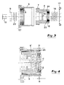
- reference numeral 1 generally designates an eccentric gear made according to the invention, which gear at its input side is connected to a driving source in the form of a motor 2, for instance an electric motor. At its output side, the gear 1 is connected to an application object which is schematically shown at reference numeral 3.
- this object is assumed to be in the form of a valve housing comprising a valve spindle 4 that is turn- or rotatable for the regulation of the appurtenant valve.
- the valve spindle 4 comprises a thread, it is also axially movable.
- One component in the gear 1 consists of an outer frame-forming ring 5 which on its inside has a first gear ring 6 arranged to cooperate in a known manner with a second gear ring 7 on a rotatable body designated 8.
- the first outer gear ring 6 has a larger pitch diameter than the gear ring 7 and has a certain number of inwardly directed teeth, while the inner gear ring 7 has a smaller number of outwardly directed teeth of which only a minor number, for instance one, is in engagement with the outer gear ring 6, in that the inner gear ring is eccentrically mounted in bearings relative to the outer one.
- the body 8 that carries the inner gear ring 7 at its one end is carried by a bearing 9, e.g.
- a ball bearing that is arranged outside an eccentric body 10 which in turn is co-rotatively connected with a shaft 11 pertaining to the motor 2 and which is centrically mounted in the same in bearings.
- the eccentric body 10 forms the driving, rotatable input element of the eccentric gear, to which the shaft 11 is connectable.
- the gear change of the gear is dependent upon the total number of teeth in the two gear rings 6, 7. Presume that the number of teeth in the outer gear ring 6 amounts to 90 while the number of teeth in the inner gear ring 7 amounts to 89.
- the inner gear ring 7 When the shaft 11 and the eccentric body 10 rotate, then the inner gear ring 7 will generate on the outer gear ring 6 like a planet wheel and thereby turn around its axis of symmetry in the opposite direction of rotation relative to shaft 11, more specifically by 1 tooth pitch since the difference in numbers of teeth is 1.
- the shaft 11 In order to make the inner gear ring 7 and, thereby, the body 11 rotate a whole revolution, the shaft 11 has to rotate 89 revolutions. In other terms, a gear change or a reduction in the number of revolutions of 89:1 is obtained.
- the body 8 carrying the inner gear ring 7 is elongated and has in the example according to fig 1 to 3 the shape of a casing or casing-like part, which, at its end being distanced from the gear ring 7, has a first means that is ready to be connected or be brought into engagement with a complementary second means on the valve spindle 4, which constitutes the element driven by the gear.
- said first engagement means consists of an internal third gear ring 12 that is connected or integrated with the free end portion of the casing part.
- the complementary engagement means on the valve spindle 4 consists of a cooperating fourth gear ring 13 with outwardly directed teeth, said ring being provided upon a disk-shaped body 14 which is co-rotatively connected with the valve spindle 4.
- the casing part 8 has a geometrical axis of symmetry designated A (see fig 2) which is oblique relative to an imaginary geometrical axis of symmetry B through the centre of the outer gear ring 6.
- A geometrical axis of symmetry
- the casing part is submitted to a nutating or tilting motion during which its axis of symmetry A moves like a generatrice along an imaginary conical surface, more specifically around a cone apex designated C that is axially distanced by a considerable stretch from the gear rings 6, 7.
- each one of the gear rings 6, 7 has a conical basic shape with small ends and large ends. More specifically, the conicity is such that the small ends of the gear rings point into the same direction.
- a shoulder 15 is arranged which according to the example has the form of an intermediate wall. Against this wall is placed the one end of a pressure spring 16, for instance a helical pressure spring, whose opposite end is placed against the tooth-carrying disk-body 14 being carried by the spindle shaft 4.
- the spring 16 has the purpose of always keeping the casing part 8 spring-tensioned in a direction towards the motor 2, more specifically for keeping the tooth/teeth of the inner gear ring 7 being engaged with analogous teeth on the outer gear ring 6 in a gap-free engagement with the latter. In this way, a distinct and silent force transmission is secured between the gear rings.
- a radial seal 17 preferably a standard seal, which according to the example in fig 1 to 3 has the shape of a cross-sectionally V-shaped, elastic ring, e.g. of plastic or rubber.
- the sealing ring 17 is located in the cross section D-D.
- the frame ring 5 has lugs 18, 19, a flange or similar means for fastening the gear 1 to, on one hand, the motor 2 and, on the other hand, the application object 3. More specifically, the lugs 18 allow a screw-fastening of the gear to a flange 20 on the motor 2, while the lugs 19 may be screwed to suitable connecting taps or means 21 which in turn are stiffly fastened to the application object 3. In its screw-fastened state as shown in fig 1, the frame ring is immovable in the space relative to both the motor 2 and the application object 3.
- a cup spring 22 operates between the bearing 9 and an internal shoulder in the casing part 8, with the purpose of keeping the bearing in place and lightly stressing the same axially in order to avoid any looseness.
- the comparatively elongated casing part 8 will perform a nutating or tilting motion when the inner gear ring 7 makes a generating motion against the outer gear ring 6 in a way similar to a planet wheel.
- the size of the angle ⁇ that the axis of symmetry A forms with the axis of symmetry B is determined by on one hand the size of the eccentricity of the gear rings 6, 7 and on the other hand the distance between the cross planes E-E and D-D. At a small distance between these cross planes, a comparatively large angle ⁇ is required for a certain eccentricity. With increasing distance between the cross planes, the angle a may be reduced.
- the angle ⁇ may lie within the range of 0,1 to 3°, suitably 0,2 to 2° or preferably 0,3 to 1°.
- the axial length of the casing part 8 should amount to at least 50 % of the diameter of the gear ring 7 and suitably more in order not to necessitate too large angles ⁇ .
- the inner gear ring 12 on the free end portion of the casing part 8 has a width that is smaller than the width of the outer gear ring 13 on the disk body 14.
- the inner edge of the gear ring 12 is located at a certain distance from a shoulder surface 23 in the casing part, whereby a gap 24 is created between the shoulder and the gear ring.
- a valve spindle 4 with threads may also be connected with the gear without losing the axial mobility that is necessary for adjusting the valve in question into different regulating positions. It should be obvious that the gear attends to a gear reduction of the relatively high rotation speed and low torque to a reduced rotation speed or deflection of angle of rotation, these being dependent as a function of the factual gear change, and an increased torque of the valve spindle 4.
- the gear may easily and quickly be connected to the valve spindle without the necessity of any special couplings of the kind that has been previously required between an output shaft mounted in bearings of the gear and the rotation element in question of the application object.
- the described gear assumes a very simple construction, comprising extremely few components, namely substantially only the frame ring 5, the casing part 8, the bearing 9 and the eccentric body 10, and where appropriate, the spring 16 and the sealing 17.
- the gear can be produced at a very low cost in comparison with previously known eccentric gears.
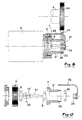
- fig 4 a modified embodiment is shown, according to which the V-shaped sealing ring 17 has been replaced by a simple O-ring 25. Also this sealing ring is located in the cross plane D-D in which the cone apex C of the casing part 8' is located.
- fig 3 it is indicated how the gear ring 12 exerts slewing motions with restricted motion deflections under the nutating motion of the casing part.
- a major part of the upper portion of the O-ring is shown situated somewhat to the right of the cross plane D-D, while the major part of the lower portion is shown to the left of the same plane.
- the O-ring 25, which is relatively stiff in radial direction, simplifies the assemblage of the gear relative to the spindle.
- the cone apex C should be located on the axis of symmetry B in order to obtain the best possible contact between the gear rings 6 and 7.
- gear ring 12 related with the casing part is shown as an inner ring intended to be connected with an outer gear ring on the driven element of the application object, also the reversed relation is possible, i.e., an outer gear ring on the casing part and an inner gear ring on the driven element.
- the gear comprises a casing part 8", which is mounted in bearings not only by means of a first eccentrically placed bearing 9, but also by means of a centrically placed second bearing 26 at the free end of the casing part.
- This bearing is kept in place by means of a holder which is designated 27 in its entirety and which comprises an angle-shaped arm 28 being stiffly connected with a frame ring 5', and a support ring 29 being carried by said arm.
- the eccentric body 10' which in this case has a counter-weight 30, has an extension 31 whose free end is mounted in bearings in the support ring 29.
- the casing part 8" has an external fifth gear ring 32 which forms the first engaging or force-transmitting means of the gear.
- the gear ring 32 engages with a gear belt 33 which in turn engages with a gear belt disk 34 on the driven shaft 4'.
- the gear ring 32 is located in one and the same cross plane as the cone apex around which the casing part 8" exerts its nutating motion. Also in this case the gear ring 32 makes a slewing or tilting motion which, however, has a limited deflection, wherefore the resilient or flexible gear belt 33 manages to absorb the motions in question without any problems.
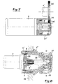
- fig 7 an embodiment is shown according to which the stationary holder 27' for the bearing 26' has the shape of a cover in which there is an opening 35 for a gear wheel 34' whose teeth are brought into direct engagement with the gear ring 32'.
- the other engaging means associated with the driven element 4' consists of the gear wheel 34' in lieu of the gear belt 33 as according to the embodiment of fig 5 and 6.
- FIG. 8 an embodiment is shown according to which the gear in question is formed for direct connection with a cable or chain transmission.
- an outer, carrying frame ring 5" is fixedly attached to a carrier 36 of a suitable type.
- the frame 5" carries a bearing 26" on which a chain wheel or sprocket 37 is rotatably mounted, which in turn is co-rotatively connected with a shaft 38 that constitutes an extension of a casing part designated 8"'.
- this casing part On its disk-shaped portion 39, this casing part carries an inner gear ring 7 which in a previously described manner cooperates with an outer gear ring 6 on the inside of a part-ring 5"' that is detachably connected with the frame ring 5".
- a motor 2 is connected with the gear.
- the wheel 37 has a toothing 40 for engaging with the chain in question. This toothing constitutes the first engaging means of the gear.
- said first engaging means 40 is located in the cross plane D-D in which the cone apex C as well as the bearing 26" are located.
- the distance between the cross plane D-D and the cross plane for the gear rings 6, 7 is comparatively large (larger than the diameter of the gear ring 7), implying that the obliquity angle ⁇ ° between the previously mentioned shafts A and B may be comparatively small.
- this angle amounts to merely about 0,20 - 0,30°.
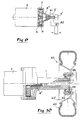
- an eccentric gear is schematically illustrated, which has the purpose of transforming a rotary motion of an output shaft of a motor 2 into an axial, reciprocating motion of a driven element, e.g. in the form of a swivelling arm 4" to an application object 3' in the form of a stationary holder.
- a screw or screw-shaped tap 41 is co-rotatively connected with the casing part 8"", the external thread of said screw or screw-shaped tap being in engagement with an internal thread in a through-hole through the holder 3'.
- the screw 41 When the screw 41 is brought to rotate by means of the eccentric gear, with a speed of rotation that is reduced in comparison with the speed of rotation of the motor 2, then the screw 41 will - thanks to the thread engagement - be submitted to an axial motion which is directed either to the left or to the right on the drawing, depending on the direction of rotation of the casing part. In turn, this axial motion of the screw is transformed into a slewing motion of the arm 4" that is pivotable relative to the holder 3' via a joint designated 42.
- the screw tap 41 may either be fixedly connected with the casing part 8"" or be provided with splines. Then the casing part, and thereby the cone apex C, will be moved axially relative to the object 3'. This motion is usually small and can be accepted.
- the threaded tap 41 may constitute the application object and be provided with splines which engage into corresponding splines in the casing part 8"" (cf. fig 1).
- a gear 1 has the purpose of transmitting a torque from a motor 2, e.g. a hydraulic motor, to a wheel 43 with a tyre, which wheel comprises a rubber tyre 43' and a rim part 43".
- a motor 2 e.g. a hydraulic motor
- the wheel 43 is mounted in a bearing 44 which is located in the same cross plane as the cone apex of a nutating casing part 8"', in a previously described manner.
- the tilting motions in question can be accepted.
- the rim part 43" forms the driven element of the application object, which element may be easily connected via a screw joint 46 with a ring flange 45 that is co-rotatively connected with the casing part 8'".
- the invention is not restricted merely to the embodiments as described and shown in the drawings.
- the outer gear ring may, e.g., be cylindrical at the same time as the inner gear ring is conical.
- both gear rings substantially cylinder-shaped.
- the body in question may also be formed in another way.
- the elongated body could also consist of a disk-shaped, tooth-carrying part and a central axial tap, being directly connected or integrated with the former.
- the wheel 37 may be modified in different ways in order to make possible the connection of the gear with other objects than just a chain.
- the wheel may for instance be formed for being connected with a transmission belt, e.g., a belt encompassed by a patient-lift, it being possible to effect the force transmission by a friction engagement between the wheel and the belt.
Landscapes
- Engineering & Computer Science (AREA)
- General Engineering & Computer Science (AREA)
- Mechanical Engineering (AREA)
- Retarders (AREA)
- Gears, Cams (AREA)
Claims (9)
- Engrenage excentrique destiné à transmettre un couple ou une force à un élément mené (4, 4', 4") mobile en rotation, d'un élément menant mobile en rotation ou d'entrée (10, 11), comprenant deux anneaux d'engrenage coopérants (6, 7) avec différents grands diamètres primitifs, dont un premier anneau extérieur (6) doté du plus grand diamètre a un certain nombre de dents dirigées vers l'intérieur et un second anneau d'engrenage intérieur a un plus petit nombre de dents dirigées vers l'extérieur, dont seulement un petit nombre, par exemple 1, est en prise avec l'anneau d'engrenage extérieur dans lequel l'anneau d'engrenage intérieur est monté dans des roulements de façon excentrique par rapport à celui qui est extérieur, le rapport de vitesse entre lesdits éléments menant et mené dépendant du nombre total de dents dans chaque anneau d'engrenage, caractérisé en ce qu'il est sous la forme d'une unité distincte (1) pouvant être reliée à un objet d'application arbitraire (3, 3') dans lequel l'élément mené (4, 4', 4") est compris, en ce que l'anneau d'engrenage intérieur (7) est relié ou intégré d'une façon connue en soi à un corps allongé mobile en rotation (8, 8', 8", 8"', 8""), dont l'axe de rotation géométrique (A) est oblique par rapport à un axe de symétrie géométrique imaginaire (B) passant par le centre de l'anneau d'engrenage extérieur (6) et qui, pendant le mouvement de génération de l'anneau d'engrenage intérieur (7) contre l'anneau d'engrenage extérieur, est soumis à un mouvement de nutation, pendant lequel l'axe de rotation (A) du corps se déplace comme une génératrice le long de la surface d'enveloppe d'un cône imaginaire, plus précisément autour d'un sommet de cône (C) qui est à une certaine distance axiale des anneaux d'engrenage (6, 7), et en ce que ledit corps, dans une zone sensiblement à la même distance des anneaux d'engrenage (6, 7) que ledit sommet de cône (C), est associé à un premier moyen (12, 32, 40, 41) qui est prêt à être couplé à un second moyen complémentaire (13, 33, 34') dépendant de l'élément mené (4, 4', 4") de l'objet d'application de (3, 3'), ou à être amené en prise avec celui-ci, afin de former conjointement avec ce second moyen une unité de transmission de force située sensiblement dans un plan (D-D) qui est perpendiculaire par rapport audit axe de symétrie (B), dans quel plan ledit sommet de sommet de cône (C) est situé.
- Engrenage excentrique selon la revendication 1, caractérisé en ce que le corps allongé a la forme d'un boítier ou d'une partie en forme de boítier (8, 8', 8", 8"', 8"").
- Engrenage excentrique selon la revendication 1 ou 2, caractérisé en ce que le premier moyen de prise ou de transmission force a la forme d'un troisième anneau d'engrenage (12) qui est disposé au niveau de la partie d'extrémité de la partie formant boítier (8) qui est à une certaine distance de l'anneau d'engrenage intérieur (7) et est destiné à être amené en prise avec un quatrième anneau d'engrenage analogue (13) qui fait partie de l'élément mené (4) de l'objet d'application (3) et forme ledit second moyen de prise, l'élément mené (4) de l'objet d'application formant une partie dont la position est déterminée spécialement et détermine la position dudit sommet de cône (C).
- Engrenage excentrique selon la revendication 3, caractérisé en ce que les dents du troisième anneau d'engrenage (12) ont une plus petite longueur axiale que les dents correspondantes situées dans le quatrième anneau d'engrenage (13), afin de permettre au troisième anneau d'engrenage de se déplacer axialement par rapport à la partie formant boítier (8) sans que les anneaux d'engrenage (12, 13) ne perdent leur engrènement l'un avec l'autre, et sans que le sommet de cône (C) ne change sa position par rapport à l'objet d'application.
- Engrenage excentrique selon la revendication 3 ou 4, dans lequel les premier et second anneaux d'engrenage (6, 7) ont une forme de base conique d'une manière connue en soi, avec de petites extrémités et de grandes extrémités, et sont en prise l'un dans l'autre, les petites extrémités étant dirigées dans la même direction, caractérisé en ce que, à l'intérieur de la partie formant boítier (8), est disposé un épaulement fixe (15), par exemple une paroi intermédiaire, contre laquelle une extrémité d'un ressort de compression (16) peut buter, dont l'extrémité opposée peut buter contre l'élément mené de l'objet d'application, de sorte que le ressort, dans un état comprimé, maintient les premier et second anneaux d'engrenage coniques (6, 7) en une prise dépourvue d'interstices et chargée de façon élastique l'un avec l'autre.
- Engrenage excentrique selon la revendication 5, caractérisé en ce que le premier anneau d'engrenage extérieur (6) est prévu sur l'intérieur d'un anneau formant cadre (5) qui comporte des moyens (18, 19) destinés à relier de façon rigide et immobile l'anneau à, d'une part, l'objet d'application (3) et, d'autre part, un moteur (2), par exemple un moteur électrique, avec un arbre de sortie (11) qui est monté de façon centrée dans des roulements de manière à entraíner un corps excentrique (10) qui constitue un élément menant pour l'engrenage.
- Engrenage excentrique selon la revendication 1 ou 2, caractérisé en ce que la partie formant boítier (8") est montée dans des roulements non seulement par un premier roulement disposé de façon excentrique (9) dans la zone dudit second anneau d'engrenage (7), mais aussi par un second roulement disposé de façon centrée (26) à l'extrémité opposée de la partie formant boítier, lequel second roulement est maintenu en place au moyen d'un support immobile (27) qui détermine la position dudit sommet de cône (C), et en ce que la partie formant boítier dans la zone du second roulement (26) comporte un cinquième anneau d'engrenage externe (32, 32') qui forme ledit premier moyen de prise et a pour but d'être amené en prise avec un second moyen de prise complémentaire, par exemple une roue d'engrenage (34') ou une courroie d'engrenage (33), qui est reliée à l'élément rotatif (4') de l'objet d'application.
- Engrenage excentrique selon la revendication 1, caractérisé en ce que le corps allongé est composé, d'une part, d'une partie en forme de boítier (8"') à laquelle le second anneau d'engrenage (7') est associé, et d'autre part, d'un taraud d'arbre (38) qui s'étend le long de l'étendue de la partie formant boítier, lequel taraud, à une extrémité extérieure libre, est relié de façon co-rotative à une roue mobile en rotation (37) sur laquelle le premier moyen de prise (40) est prévu, la roue (37) étant montée dans un roulement (26") qui est situé dans le même plan transversal que le sommet de cône (C) et est supporté par une partie en forme de tuyau ou d'anneau (5").
- Engrenage excentrique selon la revendication 1, caractérisé en ce qu'un taraud extérieur (41) est compris dans le corps allongé ou la partie formant boítier (8""), lequel taraud comporte un filetage externe qui est en prise avec un filetage interne dans un trou situé dans un support fixe (3'), et lequel taraud, lorsqu'il tourne, peut être mis en mouvement axial dans les deux directions par l'intermédiaire de ladite prise par filetage, par exemple afin d'influencer un bras ou une bielle (4").
Applications Claiming Priority (3)
| Application Number | Priority Date | Filing Date | Title |
|---|---|---|---|
| SE9402701 | 1994-08-12 | ||
| SE9402701A SE9402701L (sv) | 1994-08-12 | 1994-08-12 | Excenterväxel |
| PCT/SE1995/000815 WO1996005451A1 (fr) | 1994-08-12 | 1995-07-10 | Engrenage excentrique |
Publications (2)
| Publication Number | Publication Date |
|---|---|
| EP0774087A1 EP0774087A1 (fr) | 1997-05-21 |
| EP0774087B1 true EP0774087B1 (fr) | 1999-03-24 |
Family
ID=20394906
Family Applications (1)
| Application Number | Title | Priority Date | Filing Date |
|---|---|---|---|
| EP95929274A Expired - Lifetime EP0774087B1 (fr) | 1994-08-12 | 1995-07-10 | Engrenage excentrique |
Country Status (9)
| Country | Link |
|---|---|
| US (1) | US5913744A (fr) |
| EP (1) | EP0774087B1 (fr) |
| JP (1) | JP3670013B2 (fr) |
| AU (1) | AU3267795A (fr) |
| BR (1) | BR9508568A (fr) |
| DE (1) | DE69508586T2 (fr) |
| ES (1) | ES2131848T3 (fr) |
| SE (1) | SE9402701L (fr) |
| WO (1) | WO1996005451A1 (fr) |
Families Citing this family (14)
| Publication number | Priority date | Publication date | Assignee | Title |
|---|---|---|---|---|
| SE505916C2 (sv) * | 1996-01-15 | 1997-10-20 | Gustav Rennerfelt | Anordning för vridmomentöverföring |
| EP0861995A3 (fr) * | 1997-02-28 | 1998-09-16 | Harald Weisz | Engrenage planétaire avec jeu reduit |
| DE19907912C2 (de) * | 1998-02-25 | 2002-08-14 | Harald Weisz | Exzentergetriebe |
| SE513311C2 (sv) | 1998-12-29 | 2000-08-21 | Gustav Rennerfelt | Excenterväxel |
| DE50106732D1 (de) * | 2001-05-29 | 2005-08-18 | Hermle Berthold Maschf Ag | Werkstückhalteeinrichtung für Bearbeitungsmaschinen, insbesondere Fräs- und/oder Bohrmaschinen |
| SE526568C2 (sv) | 2003-06-17 | 2005-10-11 | Rilbe & Co Hb | Anordning för vridning av en stomme till en kran |
| ITBO20030406A1 (it) * | 2003-07-01 | 2005-01-02 | Magneti Marelli Powertrain Spa | Valvola a farfalla servoassistita e provvista di una molla |
| DE102005061188B4 (de) * | 2005-12-21 | 2007-10-18 | Keiper Gmbh & Co.Kg | Getriebestufe eines Stellantriebs |
| CN101495779B (zh) * | 2006-07-31 | 2013-01-02 | 丰田纺织株式会社 | 齿轮及使用该齿轮的联接装置 |
| DE102007000313A1 (de) * | 2007-06-06 | 2008-12-11 | Hilti Aktiengesellschaft | Elektrisches Handwerkzeuggerät mit Spindellockvorrichtung |
| US20130305992A1 (en) * | 2011-02-04 | 2013-11-21 | Micro System Co., Ltd. | Rotating and holding apparatus for semiconductor substrate and conveying apparatus of rotating and holding apparatus for semiconductor substrate |
| JP2015040599A (ja) * | 2013-08-22 | 2015-03-02 | シャープ株式会社 | 減速装置 |
| JP2015102065A (ja) * | 2013-11-27 | 2015-06-04 | アイシン精機株式会社 | 弁開閉時期制御装置 |
| TW201534525A (zh) * | 2014-03-03 | 2015-09-16 | Harmonic Innovation Technology Co Ltd | 高扭力動力模組 |
Family Cites Families (9)
| Publication number | Priority date | Publication date | Assignee | Title |
|---|---|---|---|---|
| EP0233303B1 (fr) * | 1986-02-19 | 1990-10-17 | Sumitomo Heavy Industries, Ltd | Engrenage planétaire |
| US4760759A (en) * | 1986-04-15 | 1988-08-02 | Blake William L | Geared ratio coupling |
| SE464828B (sv) * | 1987-01-26 | 1991-06-17 | Gustav Bernhard Rennerfelt | Roerelseoeverfoerande anordning |
| SE460921B (sv) * | 1987-01-26 | 1989-12-04 | Gustav Rennerfelt | Excentervaexel samt foerfarande foer grafisk framstaellning av kuggar |
| JPH0627532B2 (ja) * | 1987-04-13 | 1994-04-13 | 住友重機械工業株式会社 | 遊星歯車増減速機 |
| US5232412A (en) * | 1989-07-11 | 1993-08-03 | Yue Zheng | High efficiency gear transmission |
| JPH04160257A (ja) * | 1990-10-25 | 1992-06-03 | Sumitomo Heavy Ind Ltd | 内接噛合遊星歯車構造 |
| SE470497B (sv) * | 1992-10-22 | 1994-06-06 | Gustav Rennerfelt | Kopplingsanordning vid en excenterväxel |
| SE9302907L (sv) * | 1993-09-08 | 1995-02-20 | Gustav Rennerfelt | Excenterväxel samt förfarande för framställning av en dylik växel |
-
1994
- 1994-08-12 SE SE9402701A patent/SE9402701L/ not_active IP Right Cessation
-
1995
- 1995-07-10 ES ES95929274T patent/ES2131848T3/es not_active Expired - Lifetime
- 1995-07-10 BR BR9508568A patent/BR9508568A/pt not_active IP Right Cessation
- 1995-07-10 WO PCT/SE1995/000815 patent/WO1996005451A1/fr not_active Ceased
- 1995-07-10 EP EP95929274A patent/EP0774087B1/fr not_active Expired - Lifetime
- 1995-07-10 JP JP50722896A patent/JP3670013B2/ja not_active Expired - Lifetime
- 1995-07-10 DE DE69508586T patent/DE69508586T2/de not_active Expired - Lifetime
- 1995-07-10 US US08/776,923 patent/US5913744A/en not_active Expired - Lifetime
- 1995-07-10 AU AU32677/95A patent/AU3267795A/en not_active Abandoned
Also Published As
| Publication number | Publication date |
|---|---|
| AU3267795A (en) | 1996-03-07 |
| EP0774087A1 (fr) | 1997-05-21 |
| JPH10505400A (ja) | 1998-05-26 |
| JP3670013B2 (ja) | 2005-07-13 |
| SE502228C2 (sv) | 1995-09-18 |
| US5913744A (en) | 1999-06-22 |
| ES2131848T3 (es) | 1999-08-01 |
| SE9402701L (sv) | 1995-09-18 |
| DE69508586T2 (de) | 1999-09-02 |
| DE69508586D1 (de) | 1999-04-29 |
| WO1996005451A1 (fr) | 1996-02-22 |
| BR9508568A (pt) | 1997-10-21 |
| SE9402701D0 (sv) | 1994-08-12 |
Similar Documents
| Publication | Publication Date | Title |
|---|---|---|
| EP0774087B1 (fr) | Engrenage excentrique | |
| JP7081753B2 (ja) | 2つのフレクスプラインを備える変形量制限可能式波動減速機 | |
| US5893813A (en) | Speed reducer | |
| JP3763648B2 (ja) | 2軸押出機の駆動伝達装置 | |
| RU2744418C2 (ru) | Прецизионная планетарная передача | |
| US5401220A (en) | Speed reducer with planocentric gear arrangement | |
| JPH02107822A (ja) | 伝動結合される2つの軸の相対角度調節装置 | |
| US5351568A (en) | Rotary speed changing apparatus | |
| US5383821A (en) | Speed reducer | |
| US421297A (en) | James mills | |
| RU2123627C1 (ru) | Редуктор с циклоидальным зацеплением | |
| US20100236355A1 (en) | Variable eccentricity assembly | |
| US4337671A (en) | Apparatus for translating rotary movement to rectilinear movement | |
| JP2023521792A (ja) | 回転ベアリング及びギヤボックス | |
| EP0378978B1 (fr) | Transmission par engrenages | |
| JPH0338458B2 (fr) | ||
| CN1328623A (zh) | 向力传递构件提供张力用的拉紧器 | |
| CA1300929C (fr) | Transmission mecanique | |
| EP0638397A4 (fr) | Dispositif de poignet pour robot. | |
| US12350818B2 (en) | Joint device for robot | |
| GB2443833A (en) | Nested coil springs having cam means | |
| US4478100A (en) | Automatic transmission | |
| US3864982A (en) | Kinematic mechanism for the reversible conversion of reciprocating motion to rotary motion | |
| CN2480623Y (zh) | 带行星齿轮的圆周角传动装置 | |
| SU1129439A1 (ru) | Привод дл преобразовани непрерывного вращательного движени в шаговое вращательное |
Legal Events
| Date | Code | Title | Description |
|---|---|---|---|
| PUAI | Public reference made under article 153(3) epc to a published international application that has entered the european phase |
Free format text: ORIGINAL CODE: 0009012 |
|
| 17P | Request for examination filed |
Effective date: 19970207 |
|
| AK | Designated contracting states |
Kind code of ref document: A1 Designated state(s): DE ES FR GB IT |
|
| GRAG | Despatch of communication of intention to grant |
Free format text: ORIGINAL CODE: EPIDOS AGRA |
|
| 17Q | First examination report despatched |
Effective date: 19980602 |
|
| GRAG | Despatch of communication of intention to grant |
Free format text: ORIGINAL CODE: EPIDOS AGRA |
|
| GRAH | Despatch of communication of intention to grant a patent |
Free format text: ORIGINAL CODE: EPIDOS IGRA |
|
| GRAH | Despatch of communication of intention to grant a patent |
Free format text: ORIGINAL CODE: EPIDOS IGRA |
|
| GRAA | (expected) grant |
Free format text: ORIGINAL CODE: 0009210 |
|
| AK | Designated contracting states |
Kind code of ref document: B1 Designated state(s): DE ES FR GB IT |
|
| ITF | It: translation for a ep patent filed | ||
| REF | Corresponds to: |
Ref document number: 69508586 Country of ref document: DE Date of ref document: 19990429 |
|
| ET | Fr: translation filed | ||
| REG | Reference to a national code |
Ref country code: ES Ref legal event code: FG2A Ref document number: 2131848 Country of ref document: ES Kind code of ref document: T3 |
|
| PLBE | No opposition filed within time limit |
Free format text: ORIGINAL CODE: 0009261 |
|
| STAA | Information on the status of an ep patent application or granted ep patent |
Free format text: STATUS: NO OPPOSITION FILED WITHIN TIME LIMIT |
|
| 26N | No opposition filed | ||
| REG | Reference to a national code |
Ref country code: GB Ref legal event code: IF02 |
|
| PGFP | Annual fee paid to national office [announced via postgrant information from national office to epo] |
Ref country code: DE Payment date: 20140724 Year of fee payment: 20 |
|
| PGFP | Annual fee paid to national office [announced via postgrant information from national office to epo] |
Ref country code: GB Payment date: 20140725 Year of fee payment: 20 Ref country code: FR Payment date: 20140731 Year of fee payment: 20 Ref country code: ES Payment date: 20140729 Year of fee payment: 20 |
|
| PGFP | Annual fee paid to national office [announced via postgrant information from national office to epo] |
Ref country code: IT Payment date: 20140722 Year of fee payment: 20 |
|
| REG | Reference to a national code |
Ref country code: DE Ref legal event code: R071 Ref document number: 69508586 Country of ref document: DE |
|
| REG | Reference to a national code |
Ref country code: GB Ref legal event code: PE20 Expiry date: 20150709 |
|
| REG | Reference to a national code |
Ref country code: ES Ref legal event code: FD2A Effective date: 20151026 |
|
| PG25 | Lapsed in a contracting state [announced via postgrant information from national office to epo] |
Ref country code: GB Free format text: LAPSE BECAUSE OF EXPIRATION OF PROTECTION Effective date: 20150709 |
|
| PG25 | Lapsed in a contracting state [announced via postgrant information from national office to epo] |
Ref country code: ES Free format text: LAPSE BECAUSE OF EXPIRATION OF PROTECTION Effective date: 20150711 |