EP0774220A2 - Brosse à rouleau pour installations de lavage de voiture automatisé - Google Patents
Brosse à rouleau pour installations de lavage de voiture automatisé Download PDFInfo
- Publication number
- EP0774220A2 EP0774220A2 EP96114593A EP96114593A EP0774220A2 EP 0774220 A2 EP0774220 A2 EP 0774220A2 EP 96114593 A EP96114593 A EP 96114593A EP 96114593 A EP96114593 A EP 96114593A EP 0774220 A2 EP0774220 A2 EP 0774220A2
- Authority
- EP
- European Patent Office
- Prior art keywords
- working
- roller
- elements
- working element
- element carrier
- Prior art date
- Legal status (The legal status is an assumption and is not a legal conclusion. Google has not performed a legal analysis and makes no representation as to the accuracy of the status listed.)
- Granted
Links
Images



Classifications
-
- A—HUMAN NECESSITIES
- A46—BRUSHWARE
- A46B—BRUSHES
- A46B9/00—Arrangements of the bristles in the brush body
- A46B9/06—Arrangement of mixed bristles or tufts of bristles, e.g. wire, fibre, rubber
-
- B—PERFORMING OPERATIONS; TRANSPORTING
- B60—VEHICLES IN GENERAL
- B60S—SERVICING, CLEANING, REPAIRING, SUPPORTING, LIFTING, OR MANOEUVRING OF VEHICLES, NOT OTHERWISE PROVIDED FOR
- B60S3/00—Vehicle cleaning apparatus not integral with vehicles
- B60S3/04—Vehicle cleaning apparatus not integral with vehicles for exteriors of land vehicles
- B60S3/06—Vehicle cleaning apparatus not integral with vehicles for exteriors of land vehicles with rotary bodies contacting the vehicle
-
- A—HUMAN NECESSITIES
- A46—BRUSHWARE
- A46B—BRUSHES
- A46B13/00—Brushes with driven brush bodies or carriers
- A46B13/001—Cylindrical or annular brush bodies
-
- A—HUMAN NECESSITIES
- A46—BRUSHWARE
- A46B—BRUSHES
- A46B13/00—Brushes with driven brush bodies or carriers
- A46B13/001—Cylindrical or annular brush bodies
- A46B13/005—Cylindrical or annular brush bodies made up of a series of longitudinal strips or segments
Definitions
- the invention relates to a washing or polishing roller for vehicle washing systems, with a rotatably drivable roller core, which is provided with a combination of strip-shaped working elements made of soft textile or fur-like material and optionally stiffer, flexible supporting elements, each with several working elements on a working element carrier and several Support elements are arranged on a support element carrier connected in a rotationally fixed manner to the roller core and the working diameter of the working elements is greater than the effective diameter of the supporting elements when the roller rotates freely, so that essentially only the working elements come into contact with the vehicle surface.
- washing or polishing rollers are known from DE 93 01 695 U1 and US-A-4377878.
- the working elements consist of textile material, such as felt or fabric. These are usually tabs, the radially inner ends of which are fixed to a cup-shaped support which concentrically surrounds the roll core and is firmly connected to it. The outer ends of the tabs have slots running radially to the roll axis.
- the working elements can also consist of fur or fur-like material.
- supporting elements made of flexible material are provided between the working elements. These support elements have a shorter length in the radial direction than the working elements.
- Bristles which are preferably made of plastic, or plastic strips, which are slotted at their radially outer edge, can be provided as support elements.
- the radially inner ends of the support elements are fixed to the same support, who also carries the work elements.
- the radially different lengths of the working elements and the support elements mean that essentially only the working elements come into contact with the vehicle surface.
- the support elements have the task of supporting the softer working elements so that the roller does not collapse, especially when it rotates about a horizontal axis. In particular, however, they should give the roller a certain elasticity. If the rotating roller comes into contact with the vehicle surface, the working elements partially lie on the support elements and are elastically supported by the roller core at some distance from them.
- the support elements ensure that the active current consumption of the drive motor of the roller or the torque already increase before the vehicle surface has approached the roller core.
- control pulses are generated which remove the roller somewhat from the vehicle surface by means of suitable control elements, so that approximately the same immersion depth of the vehicle surface in the roller is always ensured.
- a control system may also be dispensed with.
- the bristles as support elements and the textile strips as working elements in the axial direction of the roller are arranged alternately next to one another on the roller either in spatially separate areas or in mixed configuration.
- a roller rotating about a vertical axis which is used to wash the side surfaces of a vehicle, should have bristles at least in its lower region and textile strips in its upper region.
- the invention is therefore based on the object of providing a washing or polishing roller for vehicle washing systems of the type mentioned at the outset in which damage to vehicle parts by stuck working elements is avoided and which can be produced at low cost.
- the invention is therefore based on the idea of arranging the working element carriers such that they can be rotated relative to the roller core, and in doing so also using the support elements connected to the roller core in a rotationally fixed manner as a type of slip clutch. Due to friction between the support elements and the working element carriers or the working elements themselves, a limited torque is transmitted, which normally allows the working elements to rotate at the same speed as the rest of the roller. Since the torque that can be transmitted by friction is determined only by the pressure forces and the coefficient of friction (coefficient of friction or coefficient of friction), mainly by the material and surface properties of the interacting surfaces and the amount and distribution of the surfaces existing liquid is determined, the maximum transferable torque is independent of the respective speed of the roller.
- the working element carriers are designed as disks made of flexible material. As practice has shown, such disks can be made relatively thin with a thickness of only a few millimeters. These disks can be provided with a central, circular recess and arranged directly on the roller core between two support element carriers arranged with a corresponding axial distance. It is also possible to mount the disk with its circular recess on the support element carrier between two radially rotating rows of bristles or rows of support elements. The bristles also support the flexible disc.
- Such disks can e.g. made from felt relatively cheap.
- This and the fact that the support elements are used as a slip clutch makes it possible to arrange a relatively large number of disks as work element carriers, for example at a mutual distance of 100 mm.
- the arrangement of a relatively large number of work element carriers has the advantage that when one of the work element carriers stands still because one of its work elements has got caught on a vehicle part, only a very small area or none at all remains unwashed.
- the rotating working elements of the neighboring working element carriers cover the working area of the stopped working elements completely or partially.
- the washing elements or polishing elements which act on and come into contact with the vehicle surface are designated by the collective expression "working elements".
- These working elements can consist of rags or strips of soft textile material, such as felt, fleece, fabric or the like, or of natural or artificial fur.
- bristles made of plastic or also strips made of flexible plastic, which are slit in the radial direction come into consideration as stiffer, flexible supporting elements. If necessary, the support elements could also consist of a suitable foam.
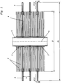
- the washing brush according to the invention has a roll core 1 which can be driven in rotation and which can consist of a tube.
- the support elements 2, preferably bristles, are fixed with their radially inner ends in a support element carrier 3.
- This can be a plastic mat.
- This initially flat plastic mat is placed around the roller core 1 and connected to the roller core in a rotationally fixed but interchangeable manner by means of suitable fastening means, for example screws.
- the support element carriers 3 have a relatively short axial length of, for example, 100 mm each. They are fixed on the roller core 1 at a mutual axial distance. This distance is dimensioned such that the working element carrier 4 described in more detail below has sufficient space between two adjacent supporting element carriers 3.
- the working element carrier 4 is expediently a disk made of flexible material.
- the disk can preferably consist of felt with a thickness of, for example, 4 mm. Instead of felt, however, other flexible materials such as fabric, plastic or the like can also be used.
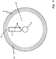
- the working element carrier 4 or 4 'designed as a disc has a central circular recess 5, the diameter of which is slightly larger than the diameter of the roller core 1, so that the disc 4, 4' is slightly bent can rotate on the roller core.
- the working element carrier 4 can also be rotatably arranged between two rows of bristles arranged at an axial distance from one another on a supporting element carrier 3 of greater length, for example 300 or 400 mm. The diameter of the circular recess 5 is then adapted to the diameter of the support element carrier 3 so that the working element carrier 4 can rotate relative to the support element carrier 3.
- the working element carrier 4 according to FIG. 3 is designed as a self-contained disc, it must be threaded onto the end of the roller core during assembly, after which a supporting element carrier is attached to the roller core.
- the roller is driven in rotation for washing or polishing a vehicle.
- the support element 3 Support elements 2 connected in a rotationally fixed manner to the roller core rotate together with the roller core. Since they are in contact with the working element carriers 4 and also the working elements 9, the working element carriers 4 and thus also the working elements 9 are carried along by friction and driven by the supporting elements 2. The rougher the surface of the working element carrier 4 and the further the working elements 9 with their radially inner ends dip into the supporting elements 2, in particular the bristles, the greater the maximum torque that can be transmitted from the supporting elements 2 to the working element carrier 4 or the working elements 9. If necessary, this torque can also be increased by projections or the like additionally attached to the working element carriers 4. If one of the working elements 9 sticks to a vehicle part, the maximum transmissible torque is overcome.
- the relevant work element 9 and the associated work element carrier are stopped while the remaining parts of the roller continue to rotate.
- the support elements or bristles 2 thus act like a slip clutch. At the same time, the support elements 2 have the desired cushioning effect.
- the working elements 9 initially lie over the support elements 2. If the contact pressure increases further, the drive motor of the roller also has a higher active current consumption. As a result of this higher active current consumption, a signal is emitted in a known manner to a servomotor, which then lifts the roller off the vehicle surface until the predetermined active current consumption is again available on the drive motor. By lifting the roller or the further movement of the vehicle relative to the roller, the stuck working element usually detaches itself from the relevant vehicle part and the relevant working element carrier 4 is then again caused by friction carried by the support elements 2.
- a working element carrier 4 ' can be provided with a radial slot 6. Thanks to this radial slot 6, the flexible working element carrier 4 'can be pushed from the side over the roller core 1, after which the slot 6 is closed by suitable connecting means.
- a Velcro fastener, metal or plastic straps or a thin plate 7, which is connected to the working element carrier 4 'by means of plastic rivets 8 or the like, can be used as suitable connecting means.
- the diameter of the working element carrier 4 corresponds approximately to the effective diameter D of the bristles. However, it can also be a little smaller.
- the lobe-shaped working elements 9 are expediently detachably connected to the working element carrier in the vicinity of the circumference thereof.
- Velcro closures come into question, one part 10a of which is sewn onto the working element carrier 4 and the other part of which is sewn onto the working element 9 or fastened in some other suitable manner.
- each working element 9 is connected to the working element carrier 4 on the upper side and the lower side via Velcro fasteners 10.
- the working elements 9 are arranged essentially in the plane of the disk-shaped working element carrier 4.
- the working elements 9 When the roller rotates freely, the working elements 9 also rotate in a radial plane. When the roller is at a standstill, they assume a different position due to their own weight. If they come into contact with the surface of the vehicle, the lobe-shaped working elements twist 9 and its radially outer regions nestle against the vehicle surface. When the contact pressure is increased, they lie almost completely over the vehicle surface and are then supported on their side facing away from the vehicle surface by the support elements 2.
- the width b of the working elements 9 is adjusted in relation to the axial distance a of the working element carrier 4 in such a way that the width b is substantially larger than the axial distance a. With an axial distance a of 100 mm, for example, the width b is approximately 100 mm.
- the working diameter D1 of the working elements 9 is the diameter that the radially outer ends of the working elements describe when the roller rotates freely. With an effective diameter D of the support elements 2 of 900 mm, the working diameter D1 can expediently be 1200 to 1300 mm.
- the working elements 9 made of felt can be divided into individual strips by slots 11 at their radially outer ends.
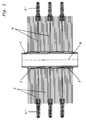
- the embodiment shown in FIG. 2 differs from the embodiment shown in FIG. 1 only in the material of the working elements.
- the working elements 9 ′′ consist of natural fur or synthetic fur. They are also connected to the working element carrier 4 by Velcro fasteners.
- the working element made of fur can be used to improve the cleaning effect 9 ′′ can also be divided into individual strips by slots 11 ′′, as shown in FIG. 3, below.
- the working element carrier 4 'designed as a disc consists of felt or fabric, there is a particularly advantageous design option.
- the working elements 9 ' can be formed by the radially outer area of the disk 4', in that the disk has a plurality of radial incisions 11 'in this area, which extend radially inward from its circumference.
- the working elements 9 ' are thus formed in one piece with the disc 4'.
- the slots 11 'and also the central recess 5 and the circumference of the disk can be punched out of a larger plate in a single operation using a suitable tool, as a result of which the production costs are substantially reduced. If the working elements 9 'wear out, the entire working element carrier 4' is simply exchanged for a new one, which requires less work than the removal and refastening of interchangeable working elements 9 according to FIG. 3.
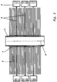
- the working elements 9 can also be connected to the working element carriers 4 in a different arrangement. While in the previously described exemplary embodiments the working elements 9 are each arranged in the plane of the disk-shaped working element carrier 4, the working elements 9 in the exemplary embodiment shown in FIG. 5 are arranged perpendicular to the plane of the working element carrier 4, ie parallel to the axis of rotation A of the roller. Here, too, the working elements 9 can be detachably connected to the working element carriers 4 in the manner described above, for example by means of Velcro fasteners or the like.
- the working element carrier 14 in each case comprises a ring 15 which is rotatably arranged on the roller core 1. Furthermore, the working elements 9 are each connected to the ring 15 by band 16. As in the previously described exemplary embodiments, the working elements 9 can be exchangeably fastened to the belts 16.
- the support elements 2, preferably the bristles mainly come into contact with the working elements 9, as a result of which their rotation is carried. The maximum torque can be changed by letting the working elements 9 extend more or less deeply into the bristles.
- the central recess 5 of the working element carrier 4 or 4 ' corresponds approximately to the diameter of the roller core 1 or the supporting element carrier 3
- the diameter D2 of the recess 5''is in Working element carrier 4 ′′ is substantially larger than the diameter d of the roller core 1 or the supporting element carrier 3.
- the working element carrier 4 ′′ is also radially movable with respect to the roller axis A.
- This radial mobility has the advantage that, in the case of strongly projecting parts of the vehicle surface, the relevant working element carrier 4 ′′ can be displaced with respect to the roller axis A, as is shown in FIG. 9.
- the working element carriers 4 ′′ provided above or below the displaced supporting element carrier keep their original position centered with respect to the roller axis A because they are in contact with vehicle parts that do not protrude as far. In this way, an even better washing or polishing effect can be achieved. Because there is one or more working element carriers opposite the roller axis A can shift with strongly projecting parts of the vehicle surface, the contact pressure of the roller does not increase or only insignificantly, so that due to the strongly projecting parts there is no premature lifting of the roller from the vehicle surface. Due to the radial mobility of the work element carrier, the work elements take on the contour of the vehicle before the roller is moved mechanically or electrically away from the vehicle by the increased contact pressure. It was found that a work element carrier shifted by projecting vehicle parts is automatically centered with respect to the roller axis when the work elements of the shifted work element carrier in question have left the projecting part again.
- the central recess 5 ′′ which is substantially larger than the diameter d of the roller core 1, also has a further advantage. You can make the diameter D2 of the recess 5 'so large that the working element carrier 4' 'can be pushed over the support elements 2 of the stationary roller for assembly.
- the support elements, in particular bristles, are bent towards the roller axis A when pushed over, but they spread again when the working element carrier in question has reached its predetermined position between two rows of bristles. The spreading of the bristles is also restored by the centrifugal force of the rotating roller.
- the working elements can either be easily detachably connected to the working element carriers or can also consist of one piece with them, as has been described with reference to FIG. 4.
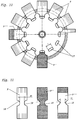
- FIGS. 10 and 11 shows a particularly cost-effective, exchangeable fastening of the working elements 9, 9 ′′, 9 ′′ ′′ to the working element carrier 4 designed as a disk.
- the working element carrier 4 which is made of flexible material, such as plastic, felt or fabric has on its radially outer region for holding each working element 9, 9 ′′, 9 ′′ ′′ an elongate cutout 17 which extends essentially in the circumferential direction.
- Each working element 9, 9 ′′, 9 ′′ ′′, as shown in FIG. 11, is designed in the form of a strip.
- the working element 9 consists of felt, the working element 9 ′′ made of fur, the working element 9 ′′ ′′ made of felt or fabric. It is equipped with fur at both ends.
- the width b of the working elements 9, 9 ′′, 9 ′′ ′′ is greater than the length l of the cutout 17.
- the working elements 9, 9 ′′, 9 ′′ ′′ each have two lateral recesses 18 in their central region. Through these recesses 18, the working elements 9, 9 ′′, 9 ′′ ′′ are tapered in their central region to a width b1, which corresponds approximately to the length l of the cutout 17.
- the working element is pulled halfway through the associated cutout 17.
- the width of the cutout 17 must be dimensioned accordingly large so that the working element can be pulled through in the folded or compressed state, although its width b is greater than the length l of the cutout 17.
- each working element 9, 9 ′′, 9 ′′ ′′ is very simple with the working element carrier 4 connectable and can be easily replaced even when worn. Both the work elements and the work element carrier can be produced by stamping. There is very little waste.
Landscapes
- Engineering & Computer Science (AREA)
- Mechanical Engineering (AREA)
- Brushes (AREA)
- Vehicle Cleaning, Maintenance, Repair, Refitting, And Outriggers (AREA)
- Finish Polishing, Edge Sharpening, And Grinding By Specific Grinding Devices (AREA)
- Cleaning By Liquid Or Steam (AREA)
- Electrical Discharge Machining, Electrochemical Machining, And Combined Machining (AREA)
- Polishing Bodies And Polishing Tools (AREA)
Applications Claiming Priority (2)
| Application Number | Priority Date | Filing Date | Title |
|---|---|---|---|
| DE19542544 | 1995-11-15 | ||
| DE19542544 | 1995-11-15 |
Publications (3)
| Publication Number | Publication Date |
|---|---|
| EP0774220A2 true EP0774220A2 (fr) | 1997-05-21 |
| EP0774220A3 EP0774220A3 (fr) | 1999-05-12 |
| EP0774220B1 EP0774220B1 (fr) | 2001-11-28 |
Family
ID=7777509
Family Applications (1)
| Application Number | Title | Priority Date | Filing Date |
|---|---|---|---|
| EP96114593A Expired - Lifetime EP0774220B1 (fr) | 1995-11-15 | 1996-09-12 | Brosse à rouleau pour installations de lavage de voiture automatisé |
Country Status (5)
| Country | Link |
|---|---|
| EP (1) | EP0774220B1 (fr) |
| KR (1) | KR970026614A (fr) |
| AT (1) | ATE209457T1 (fr) |
| DE (2) | DE59608315D1 (fr) |
| ES (1) | ES2167500T3 (fr) |
Cited By (1)
| Publication number | Priority date | Publication date | Assignee | Title |
|---|---|---|---|---|
| EP3213969B1 (fr) * | 2016-03-01 | 2023-06-14 | Favagrossa Edoardo S.r.l. | Brosse rotative pour systèmes de lavage, en particulier pour le lavage de véhicules |
Families Citing this family (6)
| Publication number | Priority date | Publication date | Assignee | Title |
|---|---|---|---|---|
| DE29806221U1 (de) * | 1998-02-28 | 1999-07-01 | WashTec Holding GmbH, 86153 Augsburg | Behandlungselemente für Bürsten von Autowasch- und Polieranlagen |
| ATE226797T1 (de) * | 1998-02-28 | 2002-11-15 | Washtec Holding Gmbh | Behandlungselemente für bürsten von autowasch- oder polieranlagen |
| DE29916541U1 (de) * | 1999-09-20 | 2001-02-08 | California Kleindienst Holding GmbH, 86153 Augsburg | Waschbürste für Kfz-Waschanlagen |
| IT1313977B1 (it) * | 1999-10-28 | 2002-09-26 | Favagrossa Edoardo Srl | Spazzole perfezionato particolarmente studiato per impianti dilavaggio automatico e/o per la lucidatura di autoveicoli in genere. |
| DE202008003088U1 (de) | 2007-09-17 | 2009-02-19 | Allguth Gmbh | Schnellwechselsystem für Autowaschaggregate |
| CA2854475C (fr) * | 2011-11-02 | 2016-07-19 | Belanger, Inc. | Moyeu eclaire pour un composant de systeme lavage de vehicules |
Family Cites Families (5)
| Publication number | Priority date | Publication date | Assignee | Title |
|---|---|---|---|---|
| US4324017A (en) * | 1980-09-16 | 1982-04-13 | Viehe John S | Rotary device for treating work surfaces |
| US4377878A (en) * | 1981-02-11 | 1983-03-29 | Pecora Daniel P | Vehicle finishing device |
| DE9301629U1 (de) * | 1993-02-05 | 1993-03-25 | Fa. Vöroka, 7519 Eppingen | Schwimmbadüberdachung aus mehreren auf Laufschienen verschiebbaren, bogenförmig gewölbten Teilschalen |
| DE9301692U1 (de) * | 1993-02-08 | 1994-06-09 | Kleindienst Gmbh, 86153 Augsburg | Waschbürste für Autowaschanlagen |
| DE9301695U1 (de) * | 1993-02-08 | 1994-06-09 | Kleindienst Gmbh, 86153 Augsburg | Textile Waschbürste mit Stützelementen für Autowaschanlagen |
-
1996
- 1996-09-12 DE DE59608315T patent/DE59608315D1/de not_active Expired - Fee Related
- 1996-09-12 AT AT96114593T patent/ATE209457T1/de not_active IP Right Cessation
- 1996-09-12 ES ES96114593T patent/ES2167500T3/es not_active Expired - Lifetime
- 1996-09-12 EP EP96114593A patent/EP0774220B1/fr not_active Expired - Lifetime
- 1996-11-13 DE DE19646783A patent/DE19646783C2/de not_active Expired - Fee Related
- 1996-11-14 KR KR1019960054089A patent/KR970026614A/ko not_active Withdrawn
Cited By (1)
| Publication number | Priority date | Publication date | Assignee | Title |
|---|---|---|---|---|
| EP3213969B1 (fr) * | 2016-03-01 | 2023-06-14 | Favagrossa Edoardo S.r.l. | Brosse rotative pour systèmes de lavage, en particulier pour le lavage de véhicules |
Also Published As
| Publication number | Publication date |
|---|---|
| EP0774220A3 (fr) | 1999-05-12 |
| EP0774220B1 (fr) | 2001-11-28 |
| DE19646783A1 (de) | 1997-05-22 |
| ES2167500T3 (es) | 2002-05-16 |
| KR970026614A (ko) | 1997-06-24 |
| DE59608315D1 (de) | 2002-01-10 |
| DE19646783C2 (de) | 1998-11-05 |
| ATE209457T1 (de) | 2001-12-15 |
Similar Documents
| Publication | Publication Date | Title |
|---|---|---|
| DE60123502T2 (de) | Verfahren und Vorrichtung zum Aufbringen von Klebestreifen | |
| DE2733091C2 (de) | Vorrichtung zur Bearbeitung der Oberfläche von unregelmäßige Konturen aufweisenden Körpern | |
| DE2822686C2 (fr) | ||
| EP0875171B1 (fr) | Cylindre de travail, en particulier cylindre de nettoyage pour installations de lavage pour véhicules | |
| DE2941293C2 (fr) | ||
| EP0774220B1 (fr) | Brosse à rouleau pour installations de lavage de voiture automatisé | |
| AT509612A1 (de) | Vorrichtung zum verarbeiten von garten-, erdgut und dergleichen | |
| DE69309217T2 (de) | Verfahren und Vorrichtung zum Schneiden einer Keilnut in einer Walze | |
| DE2121182C3 (de) | Kupplungsriemenscheibe für einen Riementrieb | |
| EP3219440A1 (fr) | Segment operatoire de machine de travail du sol, systeme adaptateur pour une machine de travail du sol, machine de travail du sol et outil associe | |
| EP3310235A1 (fr) | Appareil de nettoyage pour agir sur une surface à nettoyer | |
| DE19818499C2 (de) | Arbeitswalze, insbesondere Waschwalze für Fahrzeugwaschanlagen | |
| DE29518089U1 (de) | Wasch- oder Polierwalze für Fahrzeugwaschanlagen | |
| EP3835684A1 (fr) | Appareil de nettoyage autonome pour modules solaires | |
| EP0300279A2 (fr) | Méthode pour conditionner un tapis de fourage coupé et rouleaux conditionneurs pour la mise en oeuvre de ce procédé | |
| DE2734437C2 (de) | Krümelwalze für Bodenbearbeitungsmaschinen | |
| DE69115499T2 (de) | Federnde borsten-kassette für den rotor z.b. einer fegmaschine | |
| DE3636319A1 (de) | Vorrichtung bei rotoregge | |
| EP0865727B1 (fr) | Lame de coupe pour vis mélangeuse dans une remorque mélangeuse de fourage | |
| DE29620104U1 (de) | Streifenförmiges Arbeitselement für Wasch-, Trocknungs- und Polierwalzen | |
| DE19634545C1 (de) | Wasch- oder Polierwalze für Fahrzeugwaschanlagen | |
| DE1757691A1 (de) | Kreiselmaeher | |
| DE3431333A1 (de) | Bodenwalze fuer die ackerbestellung | |
| DE19704181C1 (de) | Wasch-, Trocknungs- oder Polierwalze für Fahrzeugwasch- und/oder -polieranlagen | |
| DE102007016191A1 (de) | Vorrichtung und Verfahren zum Reinigen von Auflageleisten |
Legal Events
| Date | Code | Title | Description |
|---|---|---|---|
| PUAI | Public reference made under article 153(3) epc to a published international application that has entered the european phase |
Free format text: ORIGINAL CODE: 0009012 |
|
| AK | Designated contracting states |
Kind code of ref document: A2 Designated state(s): AT BE CH DE DK ES FI FR GB IT LI LU NL PT SE |
|
| PUAL | Search report despatched |
Free format text: ORIGINAL CODE: 0009013 |
|
| AK | Designated contracting states |
Kind code of ref document: A3 Designated state(s): AT BE CH DE DK ES FI FR GB IT LI LU NL PT SE |
|
| RHK1 | Main classification (correction) |
Ipc: A46B 13/02 |
|
| 17P | Request for examination filed |
Effective date: 19990731 |
|
| RAP1 | Party data changed (applicant data changed or rights of an application transferred) |
Owner name: WASHTEC HOLDING GMBH |
|
| GRAG | Despatch of communication of intention to grant |
Free format text: ORIGINAL CODE: EPIDOS AGRA |
|
| GRAG | Despatch of communication of intention to grant |
Free format text: ORIGINAL CODE: EPIDOS AGRA |
|
| GRAH | Despatch of communication of intention to grant a patent |
Free format text: ORIGINAL CODE: EPIDOS IGRA |
|
| 17Q | First examination report despatched |
Effective date: 20001127 |
|
| GRAH | Despatch of communication of intention to grant a patent |
Free format text: ORIGINAL CODE: EPIDOS IGRA |
|
| GRAA | (expected) grant |
Free format text: ORIGINAL CODE: 0009210 |
|
| AK | Designated contracting states |
Kind code of ref document: B1 Designated state(s): AT BE CH DE DK ES FI FR GB IT LI LU NL PT SE |
|
| PG25 | Lapsed in a contracting state [announced via postgrant information from national office to epo] |
Ref country code: NL Free format text: LAPSE BECAUSE OF FAILURE TO SUBMIT A TRANSLATION OF THE DESCRIPTION OR TO PAY THE FEE WITHIN THE PRESCRIBED TIME-LIMIT Effective date: 20011128 Ref country code: GB Free format text: LAPSE BECAUSE OF FAILURE TO SUBMIT A TRANSLATION OF THE DESCRIPTION OR TO PAY THE FEE WITHIN THE PRESCRIBED TIME-LIMIT Effective date: 20011128 |
|
| REF | Corresponds to: |
Ref document number: 209457 Country of ref document: AT Date of ref document: 20011215 Kind code of ref document: T |
|
| REG | Reference to a national code |
Ref country code: CH Ref legal event code: EP |
|
| REG | Reference to a national code |
Ref country code: GB Ref legal event code: IF02 |
|
| REF | Corresponds to: |
Ref document number: 59608315 Country of ref document: DE Date of ref document: 20020110 |
|
| PG25 | Lapsed in a contracting state [announced via postgrant information from national office to epo] |
Ref country code: SE Free format text: LAPSE BECAUSE OF FAILURE TO SUBMIT A TRANSLATION OF THE DESCRIPTION OR TO PAY THE FEE WITHIN THE PRESCRIBED TIME-LIMIT Effective date: 20020228 Ref country code: PT Free format text: LAPSE BECAUSE OF FAILURE TO SUBMIT A TRANSLATION OF THE DESCRIPTION OR TO PAY THE FEE WITHIN THE PRESCRIBED TIME-LIMIT Effective date: 20020228 Ref country code: DK Free format text: LAPSE BECAUSE OF FAILURE TO SUBMIT A TRANSLATION OF THE DESCRIPTION OR TO PAY THE FEE WITHIN THE PRESCRIBED TIME-LIMIT Effective date: 20020228 |
|
| ET | Fr: translation filed | ||
| NLV1 | Nl: lapsed or annulled due to failure to fulfill the requirements of art. 29p and 29m of the patents act | ||
| REG | Reference to a national code |
Ref country code: ES Ref legal event code: FG2A Ref document number: 2167500 Country of ref document: ES Kind code of ref document: T3 |
|
| GBV | Gb: ep patent (uk) treated as always having been void in accordance with gb section 77(7)/1977 [no translation filed] |
Effective date: 20011128 |
|
| PGFP | Annual fee paid to national office [announced via postgrant information from national office to epo] |
Ref country code: ES Payment date: 20020812 Year of fee payment: 7 |
|
| PGFP | Annual fee paid to national office [announced via postgrant information from national office to epo] |
Ref country code: FR Payment date: 20020821 Year of fee payment: 7 |
|
| PGFP | Annual fee paid to national office [announced via postgrant information from national office to epo] |
Ref country code: FI Payment date: 20020822 Year of fee payment: 7 |
|
| PG25 | Lapsed in a contracting state [announced via postgrant information from national office to epo] |
Ref country code: LU Free format text: LAPSE BECAUSE OF NON-PAYMENT OF DUE FEES Effective date: 20020912 Ref country code: AT Free format text: LAPSE BECAUSE OF NON-PAYMENT OF DUE FEES Effective date: 20020912 |
|
| PG25 | Lapsed in a contracting state [announced via postgrant information from national office to epo] |
Ref country code: LI Free format text: LAPSE BECAUSE OF NON-PAYMENT OF DUE FEES Effective date: 20020930 Ref country code: CH Free format text: LAPSE BECAUSE OF NON-PAYMENT OF DUE FEES Effective date: 20020930 Ref country code: BE Free format text: LAPSE BECAUSE OF NON-PAYMENT OF DUE FEES Effective date: 20020930 |
|
| PLBE | No opposition filed within time limit |
Free format text: ORIGINAL CODE: 0009261 |
|
| STAA | Information on the status of an ep patent application or granted ep patent |
Free format text: STATUS: NO OPPOSITION FILED WITHIN TIME LIMIT |
|
| PGFP | Annual fee paid to national office [announced via postgrant information from national office to epo] |
Ref country code: DE Payment date: 20021111 Year of fee payment: 7 |
|
| 26N | No opposition filed | ||
| BERE | Be: lapsed |
Owner name: *WASHTEC HOLDING G.M.B.H. Effective date: 20020930 |
|
| REG | Reference to a national code |
Ref country code: CH Ref legal event code: PL |
|
| PG25 | Lapsed in a contracting state [announced via postgrant information from national office to epo] |
Ref country code: FI Free format text: LAPSE BECAUSE OF NON-PAYMENT OF DUE FEES Effective date: 20030912 |
|
| PG25 | Lapsed in a contracting state [announced via postgrant information from national office to epo] |
Ref country code: ES Free format text: LAPSE BECAUSE OF NON-PAYMENT OF DUE FEES Effective date: 20030913 |
|
| PG25 | Lapsed in a contracting state [announced via postgrant information from national office to epo] |
Ref country code: DE Free format text: LAPSE BECAUSE OF NON-PAYMENT OF DUE FEES Effective date: 20040401 |
|
| PG25 | Lapsed in a contracting state [announced via postgrant information from national office to epo] |
Ref country code: FR Free format text: LAPSE BECAUSE OF NON-PAYMENT OF DUE FEES Effective date: 20040528 |
|
| REG | Reference to a national code |
Ref country code: FR Ref legal event code: ST |
|
| REG | Reference to a national code |
Ref country code: ES Ref legal event code: FD2A Effective date: 20030913 |
|
| PG25 | Lapsed in a contracting state [announced via postgrant information from national office to epo] |
Ref country code: IT Free format text: LAPSE BECAUSE OF NON-PAYMENT OF DUE FEES;WARNING: LAPSES OF ITALIAN PATENTS WITH EFFECTIVE DATE BEFORE 2007 MAY HAVE OCCURRED AT ANY TIME BEFORE 2007. THE CORRECT EFFECTIVE DATE MAY BE DIFFERENT FROM THE ONE RECORDED. Effective date: 20050912 |
|
| REG | Reference to a national code |
Ref country code: DE Ref legal event code: R082 Ref document number: 59608315 Country of ref document: DE |