EP0774239A2 - Appareil émetteur de lumière destiné à la polymérisation - Google Patents
Appareil émetteur de lumière destiné à la polymérisation Download PDFInfo
- Publication number
- EP0774239A2 EP0774239A2 EP96117180A EP96117180A EP0774239A2 EP 0774239 A2 EP0774239 A2 EP 0774239A2 EP 96117180 A EP96117180 A EP 96117180A EP 96117180 A EP96117180 A EP 96117180A EP 0774239 A2 EP0774239 A2 EP 0774239A2
- Authority
- EP
- European Patent Office
- Prior art keywords
- light
- curing device
- lens
- edge filter
- converging lens
- Prior art date
- Legal status (The legal status is an assumption and is not a legal conclusion. Google has not performed a legal analysis and makes no representation as to the accuracy of the status listed.)
- Granted
Links
- 230000005855 radiation Effects 0.000 claims abstract description 15
- 239000011521 glass Substances 0.000 claims abstract description 4
- 238000010521 absorption reaction Methods 0.000 claims description 4
- 229910052736 halogen Inorganic materials 0.000 claims description 3
- 150000002367 halogens Chemical class 0.000 claims description 3
- 239000000203 mixture Substances 0.000 claims 1
- 239000002250 absorbent Substances 0.000 abstract 1
- 230000008021 deposition Effects 0.000 abstract 1
- 230000002349 favourable effect Effects 0.000 description 4
- 230000003287 optical effect Effects 0.000 description 4
- 238000009423 ventilation Methods 0.000 description 3
- 238000001816 cooling Methods 0.000 description 2
- 239000005548 dental material Substances 0.000 description 2
- 230000000694 effects Effects 0.000 description 2
- 230000017525 heat dissipation Effects 0.000 description 2
- 239000002184 metal Substances 0.000 description 2
- 238000006116 polymerization reaction Methods 0.000 description 2
- 230000003595 spectral effect Effects 0.000 description 2
- 238000010276 construction Methods 0.000 description 1
- 238000011161 development Methods 0.000 description 1
- 230000018109 developmental process Effects 0.000 description 1
- 230000005670 electromagnetic radiation Effects 0.000 description 1
- 238000010438 heat treatment Methods 0.000 description 1
- 230000035699 permeability Effects 0.000 description 1
- 229920000642 polymer Polymers 0.000 description 1
Images
Classifications
-
- A—HUMAN NECESSITIES
- A61—MEDICAL OR VETERINARY SCIENCE; HYGIENE
- A61C—DENTISTRY; APPARATUS OR METHODS FOR ORAL OR DENTAL HYGIENE
- A61C19/00—Dental auxiliary appliances
- A61C19/003—Apparatus for curing resins by radiation
- A61C19/004—Hand-held apparatus, e.g. guns
Definitions
- the invention relates to a light curing device according to the preamble of claim 1, which is particularly suitable for curing dental polymers that can be polymerized under the influence of light.
- Such a light curing device is known from DE-OS 32 37 510.
- the light source is surrounded by a reflector, which is intended to focus the emerging light radiation on a converging lens.
- the plano-convex converging lens, the flat surface of which faces the light source, is then intended to focus the light rays entering there onto the light entry of a light guide.
- spectral lamps are to be used as light sources which are quite large and heavy in order to enable the introduction of monochromatic light radiation into the light guide.
- the known light curing device has a flexible light guide with a length of 2 m.
- the user is restricted in his freedom of movement by the connection via the light guide.
- a comparatively long and flexible light guide is always in danger of being broken. Even if external damage may not then be apparent, the light output of the light guide is reduced considerably without the operator noticing.
- hand-held devices are known per se, for example from DE-OS 42 11 230. Such hand-held devices usually have comparatively compact arrangements and Light sources of high energy density used, which often leads to thermal problems. Despite the comparatively high expenditure of energy, the light yield in these handheld devices can be improved.
- the invention has for its object to provide a light curing device according to the preamble of claim 1, which is improved in terms of luminous efficacy, easier to handle and yet ensures a luminous efficacy ensuring complete polymerization even over a long period.
- a light yield that is particularly favorable for light curing can be achieved despite the use of a compact hand-held device.
- the compact universal halogen lamps are used, which are also considerably cheaper than spectral lamps, the luminous efficacy is surprisingly good and does not lead to inadmissible heating in the patient's mouth or for the dental material to be hardened.
- the edge filter evaporated onto the converging lens has a particularly good reflective effect for undesired radiation, without the light radiation emitted by the halogen lamp being appreciably impeded.
- the edge filter has a particularly good permeability in the frequency range desired for the polymerization.
- the light curing device according to the invention can be implemented particularly advantageously as a hand-held device. However, there are individual advantages when it is implemented as a fixed device with a flexible light guide.
- the edge filter is applied to a convex surface of the converging lens. As far as the heat radiation reaching the edge filter is reflected, the heat radiation diverges, which is particularly favorable for heat dissipation.
- a particularly advantageous embodiment of the light curing device has a reflector which adjoins the collecting lens and / or the edge filter, the reflector cone extending between the light source and the edge filter and / or the collecting lens and the cone angle opening towards the light source.
- This reflector increases the light output after the radiation emitted in the light source is reflected and fed to the converging lens and, at the same time, improves the heat dissipation from the edge filter in a double function, in particular if the conical reflector sleeve has a metallic reflection layer.
- the converging lens is designed as a plane-convex lens, the convex surface of which, in particular, faces the light source.
- This configuration is particularly favorable in terms of assembly and the introduction of light into the light guide. Light rays reflected by the entry of light are immediately reflected back on the flat surface of the converging lens, so that they again Have the opportunity to enter the light guide.
- the converging lens is made of heat absorption glass, infrared radiation that passes through is largely absorbed and increases the temperature.
- the converging lens is spaced from the light guide, so that there is no risk that the light guide is heated inadmissibly.
- the absorption properties also serve to destroy residual heat, it being understood that with this configuration it can be advantageous to attach the edge filter to the surface facing the light guide in order to prevent the emission of heat radiation towards the light guide.
- edge filters can also be vapor-deposited on both sides of the converging lens if necessary.
- edge filter Even if basically other types of edge filter application are possible, it is preferred to vapor-deposit the edge filter. In this way, a uniform and small layer thickness with optimally low pass loss in the pass region of the filter can be achieved.
- the converging lens can be extended by further lenses in order to improve the optical quality.
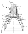
- the only figure shows a section through part of a light curing device according to the invention, showing the light guide and the converging lens.
- a light curing device 10 has a light guide 12, a converging lens 14 and a reflector 16, which are mounted in a common housing 18.
- the housing 18 also supports a light source, not shown, which is optionally provided with a reflector known per se and is arranged further to the left in the drawing.
- the light guide 12 is only partially shown in the drawing and extends with a possibly slightly bent tip over several centimeters in order to allow easy access to all necessary areas in a patient's mouth.
- the light curing device is designed as a hand-held device and for this purpose has a structure as is known per se, for example from DE-OS-42 11 230, to which reference is made in full in this respect.
- the housing 18 has a plurality of ventilation openings 20, 22 which extend essentially in a ring-shaped manner coaxial to the optical axis 24, each interrupted by ribs 26, 28 which are evenly distributed around the circumference.
- the housing is equipped in a manner known per se with a fan which is arranged behind the lamp and is operated in such a way that the ventilation openings 20, 22 act as an air inlet opening. Accordingly, very cold air sweeps along the area surrounding the converging lens 14 and the reflector 16 and brings a comparatively good cooling effect there.
- the converging lens 14 is mounted in the housing via a separate holding sleeve 30 which also carries the light guide 12.
- the light guide 12 is supported in the holding sleeve 30 via a socket 32.
- the arrangement of the converging lens 14 and the light guide 12 in the holding sleeve 30 is chosen such that a light entry 34 of the light guide 12 is clearly spaced from the converging lens 14. In the illustrated embodiment, the distance is greater than the maximum strength of the Collecting lens 14.
- the focal point of the collecting lens 14 is somewhat behind the light entry 34.
- the converging lens 14 is designed as a plano-convex lens, the flat surface facing the light guide 14 and the convex surface facing the light source. On the side facing the light source, it is vapor-coated with an edge filter 36. In addition, it is formed from a heat absorption glass that largely absorbs infrared radiation. This arrangement ensures that, in spite of the direct proximity to the light guide 12, practically only light with the desired wavelength range enters the light guide 12. For example, the edge filter can also be equipped so that unwanted UV radiation is filtered out. The spherical design of the edge filter 36 also leads to the fact that the radiation which is not transmitted is reflected over a large area and in a distributed manner.
- the reflector 16 which is located in the direct air flow on the flow channel 38 and is well cooled.
- the edge filter 36 and thus the converging lens 14 are also formed in thermal proximity to the reflector 16, and an additional, directly adjacent flow channel is opened via the ventilation opening 22, which contributes to good cooling.
- the lens 14 is supported in such a way that it is clamped between the holding sleeve 30 and the reflector 16 via a retaining ring 40, which may be elastic.
- the reflector 16 is screwed from the inside to the housing 18 so that the screw connection supports the holding sleeve 30, the converging lens 14, the holding ring 40 and the reflector 16 in succession on a corresponding holding flange 42 of the housing.
- the light radiation emitted by the light source is partially refracted in accordance with the course of the light beam 44 and then enters the light guide 12 parallel to the optical axis 24. Part it is reflected on the reflector 16, as is shown in the light beam 46, and then enters the converging lens 14 after appropriate refraction in order to emerge from it again parallel to the optical axis 24.
- this only applies to light beams with wavelengths that are passed through the edge filter 36.
- the reflector 16 is designed as a metal part and therefore has good thermal conductivity properties.
- an internally mirrored plastic part can be used instead, it being in any case favorable that the reflector widens conically towards the light source.
- the converging lens is suitably provided with an edge filter, which prevents light or electromagnetic radiation with an undesired wavelength from entering the light guide 12.
Landscapes
- Health & Medical Sciences (AREA)
- General Health & Medical Sciences (AREA)
- Veterinary Medicine (AREA)
- Epidemiology (AREA)
- Life Sciences & Earth Sciences (AREA)
- Animal Behavior & Ethology (AREA)
- Oral & Maxillofacial Surgery (AREA)
- Public Health (AREA)
- Dentistry (AREA)
- Dental Tools And Instruments Or Auxiliary Dental Instruments (AREA)
- Heating, Cooling, Or Curing Plastics Or The Like In General (AREA)
- Radiation-Therapy Devices (AREA)
- Surface Treatment Of Glass Fibres Or Filaments (AREA)
- Glass Compositions (AREA)
- Non-Portable Lighting Devices Or Systems Thereof (AREA)
Applications Claiming Priority (2)
| Application Number | Priority Date | Filing Date | Title |
|---|---|---|---|
| DE19542985 | 1995-11-17 | ||
| DE19542985A DE19542985C2 (de) | 1995-11-17 | 1995-11-17 | Lichthärtgerät |
Publications (3)
| Publication Number | Publication Date |
|---|---|
| EP0774239A2 true EP0774239A2 (fr) | 1997-05-21 |
| EP0774239A3 EP0774239A3 (fr) | 1997-12-17 |
| EP0774239B1 EP0774239B1 (fr) | 2002-05-29 |
Family
ID=7777769
Family Applications (1)
| Application Number | Title | Priority Date | Filing Date |
|---|---|---|---|
| EP96117180A Expired - Lifetime EP0774239B1 (fr) | 1995-11-17 | 1996-10-25 | Appareil émetteur de lumière destiné à la polymérisation |
Country Status (6)
| Country | Link |
|---|---|
| EP (1) | EP0774239B1 (fr) |
| JP (1) | JP2995160B2 (fr) |
| AT (1) | ATE218050T1 (fr) |
| AU (1) | AU691130B2 (fr) |
| CA (1) | CA2189498C (fr) |
| DE (2) | DE19542985C2 (fr) |
Cited By (4)
| Publication number | Priority date | Publication date | Assignee | Title |
|---|---|---|---|---|
| EP1260195A1 (fr) * | 2001-05-18 | 2002-11-27 | Firma Ivoclar Vivadent AG | Adapteur pour guides de lumière |
| EP0801932B1 (fr) * | 1996-04-17 | 2003-09-24 | DEVELODENT GmbH | Instrument dentaire |
| EP1985255A1 (fr) * | 1997-06-20 | 2008-10-29 | BioLase Technology, Inc. | Système de brosse à dents et dentifrice émettant un rayonnement électromagnétique |
| CN114364338A (zh) * | 2019-09-19 | 2022-04-15 | 3M创新有限公司 | 用于加热牙科材料的装置 |
Citations (2)
| Publication number | Priority date | Publication date | Assignee | Title |
|---|---|---|---|---|
| DE3237510A1 (de) | 1982-10-09 | 1984-04-12 | Schütz-Dental GmbH, 6365 Rosbach | Polymerisationsgeraet |
| DE4211230A1 (de) | 1992-04-03 | 1993-10-07 | Ivoclar Ag Schaan | Wiederaufladbares Lichthärtgerät |
Family Cites Families (9)
| Publication number | Priority date | Publication date | Assignee | Title |
|---|---|---|---|---|
| US4385344A (en) * | 1980-08-29 | 1983-05-24 | Dentsply Research & Development Corp. | Visible light apparatus for curing photo-curable compositions |
| US4716296A (en) * | 1982-04-26 | 1987-12-29 | Surgicorp | Apparatus for curing dental restorative composites |
| DE8226439U1 (de) * | 1982-09-20 | 1983-02-03 | Schütz-Dental GmbH, 6365 Rosbach | Lichtpolymerisationsgeraet |
| ATE44450T1 (de) * | 1983-05-06 | 1989-07-15 | Dentsply Int Inc | Geraet zum aushaerten von medizinischen und prothetischen gegenstaenden durch licht. |
| DE3405049A1 (de) * | 1984-02-13 | 1985-08-14 | ESPE Fabrik pharmazeutischer Präparate GmbH, 8031 Seefeld | Dentales bestrahlungsgeraet |
| DE3820413C1 (en) * | 1988-06-15 | 1989-11-23 | Kaltenbach & Voigt Gmbh & Co, 7950 Biberach, De | Dental handpiece for emitting radiation |
| DE8815147U1 (de) * | 1988-12-06 | 1990-04-05 | Petz, Günter, 8500 Nürnberg | Vorrichtung zum Polymerisieren von halogenlichthärtenden Kunststoffmaterialien |
| DE9214727U1 (de) * | 1992-10-29 | 1993-05-27 | Siemens AG, 8000 München | Objektiv für eine Fernsehkamera zur Aufnahme von Bildern im sichtbaren und infraroten Spektralbereich |
| JPH07303665A (ja) * | 1994-05-11 | 1995-11-21 | Osada Res Inst Ltd | 光重合用ハンドピース |
-
1995
- 1995-11-17 DE DE19542985A patent/DE19542985C2/de not_active Expired - Fee Related
-
1996
- 1996-10-25 EP EP96117180A patent/EP0774239B1/fr not_active Expired - Lifetime
- 1996-10-25 AT AT96117180T patent/ATE218050T1/de not_active IP Right Cessation
- 1996-10-25 DE DE59609257T patent/DE59609257D1/de not_active Expired - Fee Related
- 1996-11-04 AU AU70571/96A patent/AU691130B2/en not_active Ceased
- 1996-11-04 CA CA002189498A patent/CA2189498C/fr not_active Expired - Fee Related
- 1996-11-15 JP JP8305297A patent/JP2995160B2/ja not_active Expired - Fee Related
Patent Citations (2)
| Publication number | Priority date | Publication date | Assignee | Title |
|---|---|---|---|---|
| DE3237510A1 (de) | 1982-10-09 | 1984-04-12 | Schütz-Dental GmbH, 6365 Rosbach | Polymerisationsgeraet |
| DE4211230A1 (de) | 1992-04-03 | 1993-10-07 | Ivoclar Ag Schaan | Wiederaufladbares Lichthärtgerät |
Cited By (4)
| Publication number | Priority date | Publication date | Assignee | Title |
|---|---|---|---|---|
| EP0801932B1 (fr) * | 1996-04-17 | 2003-09-24 | DEVELODENT GmbH | Instrument dentaire |
| EP1985255A1 (fr) * | 1997-06-20 | 2008-10-29 | BioLase Technology, Inc. | Système de brosse à dents et dentifrice émettant un rayonnement électromagnétique |
| EP1260195A1 (fr) * | 2001-05-18 | 2002-11-27 | Firma Ivoclar Vivadent AG | Adapteur pour guides de lumière |
| CN114364338A (zh) * | 2019-09-19 | 2022-04-15 | 3M创新有限公司 | 用于加热牙科材料的装置 |
Also Published As
| Publication number | Publication date |
|---|---|
| CA2189498C (fr) | 2001-12-04 |
| EP0774239B1 (fr) | 2002-05-29 |
| CA2189498A1 (fr) | 1997-05-18 |
| DE59609257D1 (de) | 2002-07-04 |
| ATE218050T1 (de) | 2002-06-15 |
| DE19542985A1 (de) | 1997-06-19 |
| JP2995160B2 (ja) | 1999-12-27 |
| AU691130B2 (en) | 1998-05-07 |
| AU7057196A (en) | 1997-05-22 |
| EP0774239A3 (fr) | 1997-12-17 |
| JPH09168551A (ja) | 1997-06-30 |
| DE19542985C2 (de) | 2000-11-16 |
Similar Documents
| Publication | Publication Date | Title |
|---|---|---|
| DE3328090C2 (de) | Lichtübertragungsvorrichtung | |
| EP0437182B1 (fr) | Appareil à fibres optiques pour le traitement photodynamique de tumeurs | |
| DE19943393C1 (de) | Bestrahlungsgerät für Dentalwerkstoffe | |
| DE10117347B4 (de) | Laserbehandlungsgeräte mit Beleuchtungsystem | |
| EP0003312A1 (fr) | Appareil d'irradiation pour le durcissement de masses photodurcissables | |
| WO2013050587A1 (fr) | Mélangeur de lumière | |
| DE19654276A1 (de) | Vorrichtung zur berührungslosen Temperaturmessung | |
| DD274871B5 (de) | Polarisiertes licht ausstrahlende behandlungsleuchte | |
| DE19543570B4 (de) | Beleuchtungseinheit für ein Endoskop | |
| DE69904917T2 (de) | Beleuchtungseinrichtung zur erzeugung eines schattenfreien operationsfeldes | |
| EP3390895A2 (fr) | Homogénéisateur à source de lumière | |
| EP1112458A1 (fr) | Appareil d'eclairage | |
| DE3804732A1 (de) | Vorrichtung zum buendeln elektromagnetischer strahlung | |
| DE2607249A1 (de) | Uv - bestrahlungsgeraet | |
| WO1994007085A1 (fr) | Projecteur de signalisation | |
| EP1894516B1 (fr) | Système d'éclairage pour la production de lumière et l'introduction de la lumière dans une extrémité proximale d'un câble à fibres optiques d'un dispositif d'observation pour l'endoscopie ou la microscopie | |
| DE19542985C2 (de) | Lichthärtgerät | |
| DE10308602A1 (de) | Röntgenortungslichtsystem | |
| DE102012209013B4 (de) | Optisches Element und ein Leuchtmodul | |
| EP0166364A2 (fr) | Dispositif destiné à l'irradiation de matériaux dentaires | |
| WO2005116711A1 (fr) | Transducteur d'ouverture, dispositif d'eclairage pour un appareil d'observation optique et dispositif de couplage pour injecter la lumiere d'une source lumineuse dans l'extremite d'entree d'un guide d'ondes | |
| DE10145901A1 (de) | Leuchte, insbesondere Begrenzungs- oder Blinklichtleuchte für ein Kraftfahrzeug | |
| DE9421685U1 (de) | Sekundäraußenleuchte | |
| DE3427461A1 (de) | Lichtabgabevorrichtung, insbesondere fuer kraftfahrzeuge | |
| EP1902246B1 (fr) | Systemes de reflecteurs |
Legal Events
| Date | Code | Title | Description |
|---|---|---|---|
| PUAI | Public reference made under article 153(3) epc to a published international application that has entered the european phase |
Free format text: ORIGINAL CODE: 0009012 |
|
| AK | Designated contracting states |
Kind code of ref document: A2 Designated state(s): AT CH DE FR GB IT LI SE |
|
| PUAL | Search report despatched |
Free format text: ORIGINAL CODE: 0009013 |
|
| AK | Designated contracting states |
Kind code of ref document: A3 Designated state(s): AT CH DE FR GB IT LI SE |
|
| 17P | Request for examination filed |
Effective date: 19980114 |
|
| 17Q | First examination report despatched |
Effective date: 20000714 |
|
| RAP1 | Party data changed (applicant data changed or rights of an application transferred) |
Owner name: IVOCLAR VIVADENT AG |
|
| GRAG | Despatch of communication of intention to grant |
Free format text: ORIGINAL CODE: EPIDOS AGRA |
|
| GRAG | Despatch of communication of intention to grant |
Free format text: ORIGINAL CODE: EPIDOS AGRA |
|
| GRAH | Despatch of communication of intention to grant a patent |
Free format text: ORIGINAL CODE: EPIDOS IGRA |
|
| GRAH | Despatch of communication of intention to grant a patent |
Free format text: ORIGINAL CODE: EPIDOS IGRA |
|
| GRAA | (expected) grant |
Free format text: ORIGINAL CODE: 0009210 |
|
| AK | Designated contracting states |
Kind code of ref document: B1 Designated state(s): AT CH DE FR GB IT LI SE |
|
| REF | Corresponds to: |
Ref document number: 218050 Country of ref document: AT Date of ref document: 20020615 Kind code of ref document: T |
|
| REG | Reference to a national code |
Ref country code: GB Ref legal event code: FG4D Free format text: NOT ENGLISH |
|
| REG | Reference to a national code |
Ref country code: CH Ref legal event code: NV Representative=s name: KELLER & PARTNER PATENTANWAELTE AG Ref country code: CH Ref legal event code: EP |
|
| GBT | Gb: translation of ep patent filed (gb section 77(6)(a)/1977) |
Effective date: 20020529 |
|
| REF | Corresponds to: |
Ref document number: 59609257 Country of ref document: DE Date of ref document: 20020704 |
|
| ET | Fr: translation filed | ||
| PLBE | No opposition filed within time limit |
Free format text: ORIGINAL CODE: 0009261 |
|
| STAA | Information on the status of an ep patent application or granted ep patent |
Free format text: STATUS: NO OPPOSITION FILED WITHIN TIME LIMIT |
|
| 26N | No opposition filed |
Effective date: 20030303 |
|
| PGFP | Annual fee paid to national office [announced via postgrant information from national office to epo] |
Ref country code: AT Payment date: 20061023 Year of fee payment: 11 |
|
| PGFP | Annual fee paid to national office [announced via postgrant information from national office to epo] |
Ref country code: SE Payment date: 20061024 Year of fee payment: 11 Ref country code: GB Payment date: 20061024 Year of fee payment: 11 Ref country code: CH Payment date: 20061024 Year of fee payment: 11 |
|
| PGFP | Annual fee paid to national office [announced via postgrant information from national office to epo] |
Ref country code: IT Payment date: 20061031 Year of fee payment: 11 |
|
| PGFP | Annual fee paid to national office [announced via postgrant information from national office to epo] |
Ref country code: DE Payment date: 20061219 Year of fee payment: 11 |
|
| EUG | Se: european patent has lapsed | ||
| GBPC | Gb: european patent ceased through non-payment of renewal fee |
Effective date: 20071025 |
|
| REG | Reference to a national code |
Ref country code: CH Ref legal event code: PL |
|
| PG25 | Lapsed in a contracting state [announced via postgrant information from national office to epo] |
Ref country code: LI Free format text: LAPSE BECAUSE OF NON-PAYMENT OF DUE FEES Effective date: 20071031 Ref country code: DE Free format text: LAPSE BECAUSE OF NON-PAYMENT OF DUE FEES Effective date: 20080501 Ref country code: CH Free format text: LAPSE BECAUSE OF NON-PAYMENT OF DUE FEES Effective date: 20071031 |
|
| PG25 | Lapsed in a contracting state [announced via postgrant information from national office to epo] |
Ref country code: AT Free format text: LAPSE BECAUSE OF NON-PAYMENT OF DUE FEES Effective date: 20071025 |
|
| REG | Reference to a national code |
Ref country code: FR Ref legal event code: ST Effective date: 20080630 |
|
| PG25 | Lapsed in a contracting state [announced via postgrant information from national office to epo] |
Ref country code: SE Free format text: LAPSE BECAUSE OF NON-PAYMENT OF DUE FEES Effective date: 20071026 |
|
| PGFP | Annual fee paid to national office [announced via postgrant information from national office to epo] |
Ref country code: FR Payment date: 20061020 Year of fee payment: 11 |
|
| PG25 | Lapsed in a contracting state [announced via postgrant information from national office to epo] |
Ref country code: GB Free format text: LAPSE BECAUSE OF NON-PAYMENT OF DUE FEES Effective date: 20071025 |
|
| PG25 | Lapsed in a contracting state [announced via postgrant information from national office to epo] |
Ref country code: FR Free format text: LAPSE BECAUSE OF NON-PAYMENT OF DUE FEES Effective date: 20071031 |
|
| PG25 | Lapsed in a contracting state [announced via postgrant information from national office to epo] |
Ref country code: IT Free format text: LAPSE BECAUSE OF NON-PAYMENT OF DUE FEES Effective date: 20071025 |