EP0774333A2 - Moule de vulcanisation de pneumatiques avec système d'évacuation d'air - Google Patents
Moule de vulcanisation de pneumatiques avec système d'évacuation d'air Download PDFInfo
- Publication number
- EP0774333A2 EP0774333A2 EP96118423A EP96118423A EP0774333A2 EP 0774333 A2 EP0774333 A2 EP 0774333A2 EP 96118423 A EP96118423 A EP 96118423A EP 96118423 A EP96118423 A EP 96118423A EP 0774333 A2 EP0774333 A2 EP 0774333A2
- Authority
- EP
- European Patent Office
- Prior art keywords
- valve
- cavern
- collar
- housing
- facing away
- Prior art date
- Legal status (The legal status is an assumption and is not a legal conclusion. Google has not performed a legal analysis and makes no representation as to the accuracy of the status listed.)
- Granted
Links
- 238000013022 venting Methods 0.000 title description 5
- 238000004073 vulcanization Methods 0.000 claims abstract description 22
- 238000009423 ventilation Methods 0.000 claims description 37
- 238000004519 manufacturing process Methods 0.000 claims description 10
- 229920002959 polymer blend Polymers 0.000 claims description 7
- 230000006835 compression Effects 0.000 claims description 6
- 238000007906 compression Methods 0.000 claims description 6
- 238000013459 approach Methods 0.000 claims description 2
- 238000004049 embossing Methods 0.000 claims description 2
- 229910052751 metal Inorganic materials 0.000 claims description 2
- 239000002184 metal Substances 0.000 claims description 2
- 230000002093 peripheral effect Effects 0.000 claims 1
- 238000000605 extraction Methods 0.000 abstract 1
- 238000002347 injection Methods 0.000 description 6
- 239000007924 injection Substances 0.000 description 6
- 239000000243 solution Substances 0.000 description 6
- 239000011148 porous material Substances 0.000 description 5
- 238000007789 sealing Methods 0.000 description 5
- 238000013461 design Methods 0.000 description 4
- 238000000034 method Methods 0.000 description 4
- 238000007493 shaping process Methods 0.000 description 4
- 238000012360 testing method Methods 0.000 description 4
- 210000002105 tongue Anatomy 0.000 description 4
- 229910000831 Steel Inorganic materials 0.000 description 3
- 238000003780 insertion Methods 0.000 description 3
- 230000037431 insertion Effects 0.000 description 3
- 239000000463 material Substances 0.000 description 3
- 239000010959 steel Substances 0.000 description 3
- NINIDFKCEFEMDL-UHFFFAOYSA-N Sulfur Chemical compound [S] NINIDFKCEFEMDL-UHFFFAOYSA-N 0.000 description 2
- 238000010521 absorption reaction Methods 0.000 description 2
- 230000000181 anti-adherent effect Effects 0.000 description 2
- 238000005452 bending Methods 0.000 description 2
- 238000007664 blowing Methods 0.000 description 2
- 238000004140 cleaning Methods 0.000 description 2
- 230000003749 cleanliness Effects 0.000 description 2
- 238000004132 cross linking Methods 0.000 description 2
- 238000005553 drilling Methods 0.000 description 2
- 230000000694 effects Effects 0.000 description 2
- 238000000227 grinding Methods 0.000 description 2
- 238000007689 inspection Methods 0.000 description 2
- 238000012423 maintenance Methods 0.000 description 2
- 238000000465 moulding Methods 0.000 description 2
- -1 polytetrafluoroethylene Polymers 0.000 description 2
- 229910052717 sulfur Inorganic materials 0.000 description 2
- 239000011593 sulfur Substances 0.000 description 2
- 241001136792 Alle Species 0.000 description 1
- 230000009471 action Effects 0.000 description 1
- 229910052782 aluminium Inorganic materials 0.000 description 1
- XAGFODPZIPBFFR-UHFFFAOYSA-N aluminium Chemical compound [Al] XAGFODPZIPBFFR-UHFFFAOYSA-N 0.000 description 1
- 239000011248 coating agent Substances 0.000 description 1
- 238000000576 coating method Methods 0.000 description 1
- 230000001427 coherent effect Effects 0.000 description 1
- 230000001186 cumulative effect Effects 0.000 description 1
- 239000004205 dimethyl polysiloxane Substances 0.000 description 1
- 238000005516 engineering process Methods 0.000 description 1
- 238000001125 extrusion Methods 0.000 description 1
- 238000005429 filling process Methods 0.000 description 1
- 206010016766 flatulence Diseases 0.000 description 1
- 230000006870 function Effects 0.000 description 1
- 238000010438 heat treatment Methods 0.000 description 1
- 238000007373 indentation Methods 0.000 description 1
- 238000001746 injection moulding Methods 0.000 description 1
- 238000009434 installation Methods 0.000 description 1
- 238000003754 machining Methods 0.000 description 1
- 230000013011 mating Effects 0.000 description 1
- 230000007246 mechanism Effects 0.000 description 1
- 238000003801 milling Methods 0.000 description 1
- 238000012946 outsourcing Methods 0.000 description 1
- 230000000149 penetrating effect Effects 0.000 description 1
- 239000004033 plastic Substances 0.000 description 1
- 229920003023 plastic Polymers 0.000 description 1
- 229920000435 poly(dimethylsiloxane) Polymers 0.000 description 1
- 229920000642 polymer Polymers 0.000 description 1
- 229920001343 polytetrafluoroethylene Polymers 0.000 description 1
- 239000004810 polytetrafluoroethylene Substances 0.000 description 1
- 230000002265 prevention Effects 0.000 description 1
- 230000002787 reinforcement Effects 0.000 description 1
- 230000000284 resting effect Effects 0.000 description 1
- 230000008719 thickening Effects 0.000 description 1
- 230000007704 transition Effects 0.000 description 1
- 239000002699 waste material Substances 0.000 description 1
- 238000004804 winding Methods 0.000 description 1
Images


Classifications
-
- B—PERFORMING OPERATIONS; TRANSPORTING
- B29—WORKING OF PLASTICS; WORKING OF SUBSTANCES IN A PLASTIC STATE IN GENERAL
- B29C—SHAPING OR JOINING OF PLASTICS; SHAPING OF MATERIAL IN A PLASTIC STATE, NOT OTHERWISE PROVIDED FOR; AFTER-TREATMENT OF THE SHAPED PRODUCTS, e.g. REPAIRING
- B29C33/00—Moulds or cores; Details thereof or accessories therefor
- B29C33/10—Moulds or cores; Details thereof or accessories therefor with incorporated venting means
-
- B—PERFORMING OPERATIONS; TRANSPORTING
- B29—WORKING OF PLASTICS; WORKING OF SUBSTANCES IN A PLASTIC STATE IN GENERAL
- B29D—PRODUCING PARTICULAR ARTICLES FROM PLASTICS OR FROM SUBSTANCES IN A PLASTIC STATE
- B29D30/00—Producing pneumatic or solid tyres or parts thereof
- B29D30/02—Solid tyres ; Moulds therefor
-
- B—PERFORMING OPERATIONS; TRANSPORTING
- B29—WORKING OF PLASTICS; WORKING OF SUBSTANCES IN A PLASTIC STATE IN GENERAL
- B29D—PRODUCING PARTICULAR ARTICLES FROM PLASTICS OR FROM SUBSTANCES IN A PLASTIC STATE
- B29D30/00—Producing pneumatic or solid tyres or parts thereof
- B29D30/06—Pneumatic tyres or parts thereof (e.g. produced by casting, moulding, compression moulding, injection moulding, centrifugal casting)
- B29D30/0601—Vulcanising tyres; Vulcanising presses for tyres
- B29D30/0606—Vulcanising moulds not integral with vulcanising presses
- B29D2030/0607—Constructional features of the moulds
- B29D2030/0617—Venting devices, e.g. vent plugs or inserts
-
- B—PERFORMING OPERATIONS; TRANSPORTING
- B29—WORKING OF PLASTICS; WORKING OF SUBSTANCES IN A PLASTIC STATE IN GENERAL
- B29L—INDEXING SCHEME ASSOCIATED WITH SUBCLASS B29C, RELATING TO PARTICULAR ARTICLES
- B29L2030/00—Pneumatic or solid tyres or parts thereof
Definitions
- the invention relates to a vulcanization mold for the manufacture of pneumatic tires with a plurality of between 1,000 and 3,000 vent holes.
- each tire vulcanization mold has to be vented so that the green tire attaches itself to the shaping tools of the vulcanization mold by inflating from the inside.
- the blank drives air in front of it radially on the outside; where this air cannot flow out, it is compressed to a pressure just below the applied inflation pressure.
- the application of pressure leads to an increase in the air dissolving capacity in the rubber, even then the air dissolving capacity is extremely small.
- Tire tread patterns are usually very detailed with longitudinal and transverse grooves and numerous, sometimes even sinuous, cuts that separate different positives such as blocks and bars. From a pneumatic point of view, the generally numerous protrusions of the shape radially inward, which mold the later tire negatives, divide the air volume to be discharged into mutually insulated chambers, each of which requires at least one ventilation channel.
- a large number of thin bores which run approximately perpendicular to the surface to be molded, are arranged in the molding tools for venting of molds, which open into ventilation channels of the outer components of the mold.
- These holes have a diameter of approximately 0.7 to 1.5 mm depending on the required drilling depth and thus on the size of the tires.
- a typical car summer tire shape has about 1,500 vent holes, a typical car winter tire shape has about 2,500 vent holes.
- European patent application 0 311 550 published in April 89, teaches to insert a pin with a circular cross section with a slightly smaller outside diameter than the inside diameter of the vent hole on the tire-shaping side in each of the known ventilation channels.
- each ventilation channel has projections which hold the respective pin, probably by means of an interference fit.
- EP-PA 0 591 745 proposes to use open-pore material at certain points of the shape that shape the tire and a pore size of less than 0.05 mm. This porosity should be large enough to allow air to escape quickly enough and small enough to prevent rubber from penetrating into the pores with subsequent blockage.
- this measure allows the ventilation gaps to be cleaned, the affected shape segment being broken down into its sub-segments.
- such shapes are very expensive due to the large number of mating surfaces, which, moreover, in most modern tire treads could not be flat but should be curved in accordance with the transverse groove course of the finished tire.
- European patent application 0 451 832 which is somewhat younger in priority than European patent application 0 440 040, also teaches the arrangement of ventilation gaps by means of fine, puzzle-like subdivision of the mold segments.
- DE-OS 19 33 816 see claim 6
- JP-A-76 91 423, JP-A-51-119776 and US Pat. Nos. 4,691,431 and 4,708,609 also point in this direction.
- German laid-open documents 22 00 314 from July 1973, 25 24 538 from December 1976 and 31 42 288 from May 1983 disclose devices for the production of non-driven injection molded parts.
- a single ventilation channel is arranged concentrically to the axis of rotation of the cavity and opens into an evacuator, which creates a largely vacuum in the mold before the polymer mixture starts to be injected.
- the residual air pressure can be very low because there is only one sealing surface, which also has a short arc length.
- a valve with a conical valve disc closes the ventilation channel.
- valve closure is effected directly (DE-OS 22 00 314 and DE-OS 31 42 288) by the impact of the polymer mixture flow on the cavity-side surface of the valve plate or indirectly (DE-OS 25 24 538) by the delivery pressure acting on one side caused bending of a plate, which is transferred to the valve plate by a sliding mechanism.
- the very early closing of the valve ensures that none of the polymer mixture penetrates into the gap between the seat surface and the conical surface of the valve disc facing away from the cavity. In this way, complete freedom from streaking is achieved and a sticking problem of the valve is avoided from the outset; a weak coil spring is therefore sufficient to open the valve when the finished vulcanized part, in particular the rubber sealing ring, is removed.
- This ventilation technique lives with the problem that the amount of residual air still present in the mold can no longer escape from the - early - closing time of the valve, but is compressed.
- This disadvantage is acceptable in good injection molds because very small amounts of residual air can be reached.
- the extruders that deliver the polymer mixture reach between 100 and 400 bar, usually around 300 bar, depending on the type of delivery pressure.
- the extremely small amount of residual air in injection molds can be compressed enormously, so that from here, at the end of the filling process, the residual air volume has shrunk to practically zero. This also increases the air absorption in the rubber through solution.
- the inventors have set themselves the task of creating a vulcanization mold that enables the production of practically non-driven pneumatic tires without machining.
- each vent hole contains a valve which is designed so that it is closed by the approaching of the blank surface and is opened again during demolding, so that the next blank to be vulcanized is embossed again with the valves open.
- each of the valves to be arranged in a vent hole according to the invention has a movable valve insert with a stem and a plate arranged thereon, which is designed as a truncated cone on the side facing away from the cavern and with an at least substantially flat surface on the side facing the cavern, the truncated surface the valve disk interacts with an adapted surface of the relevant segment of the vulcanization mold or a valve housing.
- Each of the valves is pressed into the closed position when the polymer mixture strikes while embossing the green tire, which is preferably a pneumatic tire, but conversely a weak spring pushes each of the valves into the open position when the finished tire is removed.
- the valve closes "too early", in the solution presented here for preferably evacuator-free ventilation of tire vulcanization molds, the numerous tiny valves close much more precisely - in particular not too early, which is the rule Safety is extremely important - because they are each arranged at the end of a polymer flow branch and not near the beginning. It is accepted that some of the valves close a shade too late for 100% prevention of drive-out.
- the toroidal shoots accepted in this way have had an average ring diameter of 2.8 mm, a ring width of approx. 0.3 mm and a height of approx. 0.25 mm in previous attempts; the shoots are so small that, at least in most market segments, a subsequent shoot removal is unnecessary.
- an anti-adhesive coating for example - as known per se from DE-OS 39 03 899 and EP-PA 0 228 652 - polytetrafluoroethylene or polydimethylsiloxane are recommended.
- each valve has its own, preferably cylindrical, housing, against which all movable components of the valve are held captive.
- “captive” means that no individual parts can be lost when shipping from the valve manufacturer or when screwing in or screwing out; this does not mean that the valve can no longer be dismantled.
- the valve disk can be easily dismantled for regular (albeit so far unexamined) inspection, for example via a snap lock, as detailed in claims 7 to 13 and in two exemplary embodiments.
- the valve housings (12) preferably have an outer diameter between 2.0 and 6.0 mm, more preferably between 2.0 and 4.5 mm for car tires, and more preferably between 3.0 and 6.0 mm for heavy trucks.
- the outer diameter of the valve housing should be larger than the inner diameter of the associated vent hole in the mold segment when the valve is removed.
- the oversize should be 50 to 150 ⁇ m compared to the bore, correspondingly more with a larger housing diameter and less with a smaller housing diameter.
- each valve of the vulcanization mold according to the invention has a stop on the side of the valve stem facing away from the cavern, which limits the movement of the valve insert into the open position, more preferably for valves in the shape of passenger car tires in a path between 0.3 and 1, 2 mm and for molds for heavy truck tires in a path between 0.5 and 2.0 mm.
- the extent to which the valve opening movement is limited is also referred to below as the valve lift.
- valve insert should be removable from the valve housing or - if the valve inserts are arranged without a housing directly in the respective mold segment - from the mold segment, even when using a stop to limit the valve closing path; just such a stop stands in the way of disassembly in the direction of the cavern.
- claim 7 proposes to realize the path limitation by means of a snap closure, which is designed with play, between the valve stem and the valve housing or the respective molded segment. All valve inserts can be dismantled without loosening hundreds of screw connections; the snap lock of each valve insert should be designed so that a strong pull in the direction of the cavern for disassembly and a strong push in for assembly is sufficient. Further details can be found in the exemplary embodiments and claims 8 and 9 and 10 to 13.
- Figure 1a shows in longitudinal section the left half of a mold segment 10 of a vulcanization mold 1 according to the invention;
- the vulcanization mold 1 is divided radially in the tread area as usual - but not necessary for the invention - the segments 10 are therefore radially movable.
- This segment 10 originates from the area that molds the tread area of the tire.
- Radially divided shapes usually have 7 to 13 segments 10 in the tread area, mostly 7 or 9 in car tire shapes, mostly 9 or 11 in light truck tire shapes and 11 or 13 in heavy truck tire shapes.
- vulcanization molds are generally operated in a flat arrangement, that is to say with the axis of rotation in a vertical position; the blanks are easier to insert and the vulcanized tires can be removed more easily.
- the two side parts of the mold are accordingly called the top and bottom of the mold.
- the number of ventilation openings 2 required per surface area is smaller in the side parts than in the segments 10 because the shape to be molded is not so complicated there.
- the venting in the axially movable side parts 10 is preferably carried out by means of the same valves 3 as in the radially movable segments 10; Because, apart from the less dense arrangement of the ventilation openings 2, there are no differences between the ventilation of the radially movable segments 10 and the axially movable side parts 10, the reference symbol 10 applies to both types of segments.
- valve 3 is arranged in each vent hole 2.
- the mold segment is shown in Fig. 1a without a blank; as a result, all vent valves 3 are opened in conjunction with a weak compression spring 11, as can be seen more clearly in the larger figure 2.
- the valve plates 6 protrude into the cavern.
- the return spring to reach the opening position should be as weak as possible and as strong - taking into account weight, friction and manufacturing tolerances - as necessary; In order to reach the opening position safely, it is sufficient, according to previous tests, if the pre-tension (more precisely: the pre-compression) is 1.5 times the sum of the dead weight of the valve insert and half the spring weight.
- the blank of a tire 14 is now to be inserted in a mold 1 of this type, as shown in FIG. 1 a, with open ventilation channels 2 as a result of opened valves 3.
- Figure 1b shows in an analogous representation to Figure 1a the moment when - towards the end of the "residual lifting" - the blank of the tire 14 to be embossed and vulcanized, precisely in the groove bases of the form 1, which mold the resulting areas of the tread pattern and where most ventilation channels 2 open on the cavern side, comes to the system.
- the rubber which already has a certain structural strength, presses the valves 3 against the only weak resistance of the respective compression spring into the closed position shown here.
- “Residual lifting” is understood in the tire technical language to mean the small remainder of the entire elevation or bombage, which is achieved by flatulence within the vulcanization mold and by which the profile shaping is achieved or - in the case of very deep profiles and / or very rigid reinforcements - is at least completed.
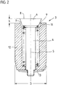
- FIG 2 shows in the same sectional plane as Figure 1 on a scale of 20: 1 a single vent valve 3 with a valve insert 4.
- the valve insert 4 comprises at least one valve plate 6 and a valve stem 5.
- the spring 11 is centered on a shoulder of the valve plate 6.
- a stop 13 with an internal thread is screwed onto the side facing away from the cavern, cooperating with an external thread on the corresponding end of the valve stem 5.
- the valve disk 6 has an end face 8 which is adapted to the shape of the cavity and is therefore essentially flat. The green tire attaches itself to this when the remainder is raised.
- the valve disc 6 is also designed as a truncated cone 7 suitable in diameter and in the cone angle to the inner conical surface 9.
- the cone angle to the dash-dotted longitudinal axis of the valve insert should be between 15 ° and 60 °; The angle of 22 ° shown here has proven itself.
- each valve insert 4 in a separate, essentially cylindrical housing 12. Together with the compression spring 11 and the stops 13, this results in a structural unit which captively summarizes all the individual parts of the valve 3;
- Such a valve 3 can be obtained completely pre-assembled from the valve manufacturer and used by the mold maker in appropriately prepared ventilation holes from the cavern.
- the insertion is preferably carried out by driving into a narrow hole; an interference fit is achieved.
- an inner bore diameter d (see FIG. 1a) of 3.35 mm with an outer housing diameter D of 3.5 mm.
- the housing 12 advantageously has a taper at the end facing away from the cavern.
- the spring 11 is preferably designed as a wire coil spring with about 10 free turns and one turn resting on a block at both ends; with a steeper winding of the spring, it appears possible to achieve a small twist of the valve insert about the dash-dotted longitudinal axis each time it opens and closes. In this way, a closing effect that is particularly uniform over the circumference of the valve plate could be achieved even longer.
- valve 3 is designed without a housing, the inner conical surface 9 must of course be drilled or milled directly at the appropriate point on the shaped segment.
- Figure 3 shows in the same sectional plane as Figure 2 and on the same scale 20: 1, a single vent valve 3 with a limitation of the valve stroke h by a defined play in a snap lock, which includes a spiral spring 16 to be inserted as a separate component.
- the valve stem 5 with the frustoconical surface 18.1 of the collar 18 facing the cavern, which is arranged on the end of the valve stem 5 facing away from the cavern, strikes the end face 16.3 of the spiral spring 16 facing away from the cavern.
- Fig. 4a shows this spiral spring 16 individually on the same scale in plan view with an external C-shaped part 16.2, which can be bent so far that the spring 16 from the side facing away from the cavern, so in Figure 3 from below, are introduced can snap into the shaft of the housing and then into the groove 15, which is arranged on the inside of the valve housing 12 or - in the case of a housingless design - in the bore in the segment in a plane perpendicular to the longitudinal axis of the valve 3.
- the spiral spring 16 also has inwardly pointing, elastically flexible legs 16.1, which are dimensioned such that they engage in the groove 17 of the valve stem 5 shown in FIG.
- the legs 16.1 should preferably stand so far that the valve insert 4 can move between the stops 18.1 and 17.1 without jamming along its dash-dotted longitudinal axis.
- these limbs 16.1 are spread from the cavern when the valve stem 5 is assembled by means of a leading conical surface 18.2 which is arranged at the end facing away from the cavern and which forms a collar-like thickening 18 of the valve stem 5 at the end of the valve stem 5 facing away from the cavern heard.
- a sleeve can be pressed or screwed in from the side facing away from the cavity up to the spring.
- the inwardly facing legs 16.1 engage in a groove 17 of the valve stem 5, which (17) is delimited to the side facing away from the cavern by the conical surface 18.1 and to the side facing the cavern by the preferably flat surface 17.1.
- the groove width w17 of the groove 17 is larger by an amount than the spring width 16; this amount is somewhat larger than the valve stroke h, so that in the closed position of the valve 3, the groove end face 17.1, which participates in the closing movement, does not penetrate as far as the end face 16.4 of the spiral spring 16 facing the cavern, thereby avoiding overdetermination in the path limitation of the valve insert 4 and thus it is possible to insert the outer conical surface 7 of the valve plate 6 into the inner conical surface 9, which results in a perfect closing of the valve 3 and freedom from misalignment between the end surface 8 of the valve plate 6 and the surrounding cavern surface.
- w16 is preferably only slightly smaller than w15 so that the clearance of approx. 20 ⁇ m required for insertion is reached.
- the above requirement is then simplified to: w17 - w16> h.
- FIG. 4b shows, in a manner analogous to that of FIG. 4a, such a variant of the spiral spring 16, in which the legs which are denoted by 16.6 here do not connect to the C-shaped part, here 16.5, not towards the inside but towards the outside.
- the legs 16.6 should engage in the housing groove 15 and the C-shaped part 16.5 in the groove 17 of the valve stem 5.
- FIG. 5 shows, in an analogous representation to FIG. 3, a single vent valve 3 with a limitation of the valve opening path by a defined play in a snap lock, here too the deflection required for a snap lock is achieved as a bend, but not as a bend of a separate spiral spring, but as a bend of the slotted end of the valve stem 5 facing away from the cavern, thus appearing at the bottom of the drawing.
- the slitting is achieved by only one slit 19, as shown here. Then, as shown, the slot 19 must be quite wide, in order not only to allow a sufficient spring deflection of the two remaining tongues towards one another during assembly and disassembly through the opening 12.1 of the housing 12 facing away from the cavity, but also in the direction perpendicular to it further longitudinal section plane through the valve 3.
- the collar 18 at the end of the valve stem 5 facing away from the cavern has a boundary surface 18.1 facing the cavern. It serves as a stop surface to limit the valve opening and is placed so that it should correspond to a valve stroke of approximately 0.5 mm in the desired opening position - which, with a valve disc diameter of approximately 2.8 mm and a cone angle to the longitudinal axis of 22 °, corresponds to shown here - on the surface of the housing 12 facing away from the cavern - or an equivalent surface in the case without a housing - strikes. The opening stroke is limited by this striking.
- the depth of the slot 19 or of the slots on the end of the shaft 5 facing away from the cavern is small enough to provide sufficient resistance to unintentional removal of the valve insert in combination with the tongue stiffness thus maintained, and on the other hand large enough to make the tongues so flexible that disassembly is tolerably easy.
Landscapes
- Engineering & Computer Science (AREA)
- Mechanical Engineering (AREA)
- Moulds For Moulding Plastics Or The Like (AREA)
- Heating, Cooling, Or Curing Plastics Or The Like In General (AREA)
- Organic Low-Molecular-Weight Compounds And Preparation Thereof (AREA)
- Check Valves (AREA)
Applications Claiming Priority (2)
| Application Number | Priority Date | Filing Date | Title |
|---|---|---|---|
| DE19543276A DE19543276C1 (de) | 1995-11-20 | 1995-11-20 | Reifenvulkanisationsform mit Entlüftung |
| DE19543276 | 1995-11-20 |
Publications (3)
| Publication Number | Publication Date |
|---|---|
| EP0774333A2 true EP0774333A2 (fr) | 1997-05-21 |
| EP0774333A3 EP0774333A3 (fr) | 1997-08-20 |
| EP0774333B1 EP0774333B1 (fr) | 2001-01-31 |
Family
ID=7777956
Family Applications (1)
| Application Number | Title | Priority Date | Filing Date |
|---|---|---|---|
| EP96118423A Expired - Lifetime EP0774333B1 (fr) | 1995-11-20 | 1996-11-16 | Moule de vulcanisation de pneumatiques avec système d'évacuation d'air |
Country Status (19)
| Country | Link |
|---|---|
| EP (1) | EP0774333B1 (fr) |
| JP (1) | JPH09141660A (fr) |
| KR (1) | KR100484002B1 (fr) |
| CN (1) | CN1066667C (fr) |
| AT (1) | ATE199002T1 (fr) |
| AU (1) | AU710458B2 (fr) |
| BR (1) | BR9605614A (fr) |
| CA (1) | CA2190720A1 (fr) |
| CZ (1) | CZ291837B6 (fr) |
| DE (2) | DE19543276C1 (fr) |
| ES (1) | ES2155564T3 (fr) |
| HU (1) | HU219783B (fr) |
| MY (1) | MY117718A (fr) |
| PL (1) | PL180855B1 (fr) |
| PT (1) | PT774333E (fr) |
| RU (1) | RU2189311C2 (fr) |
| TR (1) | TR199600886A2 (fr) |
| TW (1) | TW362061B (fr) |
| ZA (1) | ZA967689B (fr) |
Cited By (16)
| Publication number | Priority date | Publication date | Assignee | Title |
|---|---|---|---|---|
| GB2339163A (en) * | 1998-05-27 | 2000-01-19 | Dunlop Tyres Ltd | Mould vents |
| WO2003070443A1 (fr) * | 2002-02-25 | 2003-08-28 | Kabushiki Kaisha Bridgestone | Moule de vulcanisation d'article moule en caoutchouc, et procede de nettoyage dudit moule |
| US6871831B1 (en) | 2003-12-19 | 2005-03-29 | The Goodyear Tire & Rubber Company | Mold vent |
| WO2009007493A1 (fr) | 2007-07-11 | 2009-01-15 | Wd Racing Oy | Soupape de ventilation d'air d'un moule de vulcanisation |
| US7645131B2 (en) | 2006-03-03 | 2010-01-12 | Glebus Alloys Europe, S.R.O. | Venting valve to be used in venting bores of vulcanization molds |
| CN101323154B (zh) * | 2007-06-13 | 2010-12-15 | 韩国轮胎株式会社 | 轮胎硫化模具的通风装置 |
| CN106141600A (zh) * | 2016-07-01 | 2016-11-23 | 宜兴市凯诚模具有限公司 | 一种汽车轮胎模具的加工工艺 |
| CN106738495A (zh) * | 2017-02-08 | 2017-05-31 | 高密同创气门芯有限公司 | 排气装置、其组装方法及具有该排气装置的轮胎模具 |
| WO2017211476A1 (fr) | 2016-06-06 | 2017-12-14 | Continental Reifen Deutschland Gmbh | Unité de ventilation pour un moule de vulcanisation d'un pneumatique de véhicule |
| US10118357B2 (en) | 2017-01-10 | 2018-11-06 | Continental Reifen Deutschland Gmbh | Holder for arranging a foil on a mold surface of a sidewall shell of a vulcanizing mold and a vulcanizing mold having such a holder |
| DE102017223310A1 (de) | 2017-12-20 | 2019-06-27 | Contitech Mgw Gmbh | Verfahren zur Herstellung eines geformten Hohlkörpers und Vorrichtung zur Durchführung des Verfahrens |
| DE102018203053A1 (de) | 2018-03-01 | 2019-09-05 | Continental Reifen Deutschland Gmbh | Vulkanisationsform |
| DE102018205607A1 (de) | 2018-04-13 | 2019-10-17 | Continental Reifen Deutschland Gmbh | Vulkanisationsform |
| WO2021144504A1 (fr) * | 2020-01-16 | 2021-07-22 | Wd Racing Oy | Soupape de mise à l'atmosphère et procédé de montage de tige de soupape d'une soupape de mise à l'atmosphère |
| US11090842B2 (en) | 2017-04-12 | 2021-08-17 | Wd Racing Oy | Valve insert and air venting valve |
| US12072030B2 (en) | 2020-01-16 | 2024-08-27 | Wd Racing Oy | Venting valve and method of mounting valve stem of venting valve |
Families Citing this family (66)
| Publication number | Priority date | Publication date | Assignee | Title |
|---|---|---|---|---|
| GB9623770D0 (en) * | 1996-11-15 | 1997-01-08 | Sp Tyres Uk Ltd | Mould vents |
| GB9708584D0 (en) * | 1997-04-29 | 1997-06-18 | Sp Tyres Uk Ltd | Mould vents |
| DE19900596A1 (de) * | 1999-01-11 | 2000-07-13 | Dunlop Gmbh | Reifenvulkanisationsform mit in Entlüftungsbohrungen angebrachten Sperrorganen |
| WO2000006358A2 (fr) | 1998-07-27 | 2000-02-10 | Dunlop Gmbh | Moule de vulcanisation de pneumatiques comportant des organes de blocage places dans des orifices de ventilation |
| DE19833730C2 (de) * | 1998-07-27 | 2002-11-21 | Dunlop Gmbh | Reifenvulkanisationsform mit in Entlüftungsbohrungen angebrachten Ventilen |
| DE10050195C1 (de) * | 2000-10-09 | 2002-02-28 | Fraunhofer Ges Forschung | Verfahren zum Entfernen von Elementen, insbesondere Ventilen, die zumindest partiell in einer Wandung sitzen |
| JP3589644B2 (ja) | 2000-12-07 | 2004-11-17 | 日本碍子株式会社 | タイヤ成形用金型 |
| JP2002240042A (ja) * | 2001-02-15 | 2002-08-28 | Bridgestone Corp | タイヤ加硫成型用金型 |
| KR100410785B1 (ko) * | 2001-06-28 | 2003-12-18 | 한국타이어 주식회사 | 타이어 가류금형의 벤트피스 |
| DE10155931A1 (de) | 2001-11-14 | 2003-05-22 | Dunlop Gmbh | Vulkanisationsform zur Herstellung technischer Gummiprodukte |
| KR20030069699A (ko) * | 2002-02-22 | 2003-08-27 | 송영호 | 타이어 가류 금형의 에어 플러그 |
| JP2004082692A (ja) * | 2002-06-28 | 2004-03-18 | Ngk Insulators Ltd | フラップベントピース設置組立体、フラップベントピースの設置構造及び設置方法、並びにタイヤ成形用金型 |
| JP3717895B2 (ja) * | 2002-07-04 | 2005-11-16 | 韓国タイヤ株式会社 | タイヤ加硫金型のベント装置 |
| KR100498023B1 (ko) * | 2002-12-02 | 2005-07-01 | 한국타이어 주식회사 | 타이어 가류금형의 벤트장치 |
| JP4277989B2 (ja) * | 2003-07-07 | 2009-06-10 | 横浜ゴム株式会社 | タイヤ成形用金型およびタイヤ成形用金型のベントホールに使用するプラグ |
| EP1833649B1 (fr) | 2004-12-28 | 2013-02-13 | PIRELLI TYRE S.p.A. | Procede et appareil de fabrication de pneus d'autos |
| CN101076439B (zh) | 2004-12-28 | 2011-08-24 | 倍耐力轮胎股份公司 | 制造车轮轮胎的方法和设备 |
| BRPI0406493A (pt) * | 2004-12-30 | 2006-09-05 | Unilever Nv | dispositivo, equipamento e processo de fabricação de artigo de limpeza com uma massa fluìda e possuindo formas complexas e uso do artigo de limpeza |
| WO2006080378A1 (fr) * | 2005-01-28 | 2006-08-03 | Yugenkaisha T & K Corporation | Piece de conduit et matrice avec une piece de conduit attachee a celle-ci |
| KR101006894B1 (ko) * | 2008-09-17 | 2011-01-12 | 한국타이어 주식회사 | 타이어 가류 금형의 벤트 장치 |
| JP5195392B2 (ja) * | 2008-12-18 | 2013-05-08 | 横浜ゴム株式会社 | 加硫モールド用ベントユニットおよび加硫モールド |
| DE102009021697B4 (de) * | 2009-02-17 | 2015-04-02 | Ftm Formentechnik U. Metallbau Gmbh | Reinigung von Formen zur Herstellung von Reifenprofilen |
| EP2425954B1 (fr) | 2009-04-28 | 2016-03-30 | Asahi Kasei Construction Materials Corporation | Dispositif pour former une plaque en mousse de résine thermodurcissable et procédé de fabrication d'une plaque en mousse de résine thermodurcissable |
| JP5593688B2 (ja) * | 2009-12-02 | 2014-09-24 | 横浜ゴム株式会社 | タイヤ成形金型用プラグ、タイヤ成形金型及びタイヤ |
| DE102009059253B4 (de) | 2009-12-22 | 2020-12-03 | Continental Reifen Deutschland Gmbh | Vulkanisierform und Verwendung eines Entlüftungsmittels als Haltemittel von gestanzten Folien |
| JP2011198090A (ja) | 2010-03-19 | 2011-10-06 | Fuji Xerox Co Ltd | 印刷ジョブ情報管理装置、印刷装置、印刷ジョブ情報管理プログラム |
| TW201132482A (en) * | 2010-03-23 | 2011-10-01 | Xiang-Hong You | Structure of degasing set of tire mold |
| DE102010043045A1 (de) * | 2010-10-28 | 2012-05-03 | Bayerische Motoren Werke Aktiengesellschaft | Formwerkzeug mit Evakuierungseinrichtung |
| DE102010060901B4 (de) * | 2010-11-30 | 2016-02-04 | Continental Reifen Deutschland Gmbh | Vorrichtung zur Montage von Entlüftungsventilen in Formsegmente einer Vulkanisationsform für Fahrzeugreifen |
| CN102649299B (zh) * | 2011-02-24 | 2014-09-03 | 横滨橡胶株式会社 | 轮胎硫化用模具 |
| DE102011050409A1 (de) | 2011-05-17 | 2012-11-22 | Continental Reifen Deutschland Gmbh | Vulkanisierform für Fahrzeugreifen |
| DE102011053207A1 (de) | 2011-09-02 | 2013-03-07 | Continental Reifen Deutschland Gmbh | Verfahren zur Reinigung von Formteilen bzw. Formsegmenten einer Reifenvulkanisationsform |
| DE102011053663A1 (de) | 2011-09-16 | 2013-03-21 | Continental Reifen Deutschland Gmbh | Vulkanisierform für Fahrzeugreifen und Fahrzeugluftreifen, welcher mit einer vorgenannten Vulkanisierform heizgepresst ist |
| DE102012104500B4 (de) | 2012-05-24 | 2022-01-13 | Continental Reifen Deutschland Gmbh | Vulkanisierform für Fahrzeugreifen |
| DE102012106809A1 (de) | 2012-07-26 | 2014-02-20 | Continental Reifen Deutschland Gmbh | Verfahren und Vorrichtung zur Unterstützung des Entformens eines vulkanisierten Fahrzeugluftreifens |
| DE102013108384A1 (de) | 2013-08-05 | 2015-02-05 | Continental Reifen Deutschland Gmbh | Vulkanisierform für Fahrzeugreifen und Fahrzeugreifen, welcher mit einer vorgenannten Vulkanisierform heizgepresst ist |
| DE102013110664A1 (de) | 2013-09-26 | 2015-03-26 | Continental Reifen Deutschland Gmbh | Entlüftungsmittel für eine Vulkanisierform für Fahrzeugreifen |
| DE102013225160A1 (de) | 2013-12-06 | 2015-06-11 | Continental Reifen Deutschland Gmbh | Vulkanisierform für Winter- und Allseason- Fahrzeugreifen |
| DE102013225280A1 (de) | 2013-12-09 | 2015-06-11 | Continental Reifen Deutschland Gmbh | Vulkanisierform für Fahrzeugreifen |
| FR3024068B1 (fr) * | 2014-07-22 | 2016-08-12 | Michelin & Cie | Moule pour la vulcanisation d'un pneumatique comportant des elements mobiles obtenus par frittage laser |
| DE102014216869B4 (de) | 2014-08-25 | 2025-09-25 | Continental Reifen Deutschland Gmbh | Vulkanisationswerkzeug |
| JP6453018B2 (ja) * | 2014-10-01 | 2019-01-16 | 東洋ゴム工業株式会社 | 加硫成形装置 |
| KR101600324B1 (ko) | 2014-11-10 | 2016-03-21 | 한국타이어 주식회사 | 타이어 가류 금형의 스프링 벤트 장치 |
| JP6514049B2 (ja) * | 2015-06-09 | 2019-05-15 | 株式会社ブリヂストン | ゴム物品用モールド及びゴム物品用モールドの製造方法 |
| DE102015213027A1 (de) | 2015-07-13 | 2017-01-19 | Continental Reifen Deutschland Gmbh | Vulkanisierform für Fahrzeugreifen |
| DE102016206949B4 (de) * | 2016-04-25 | 2021-11-11 | Vitesco Technologies GmbH | Verfahren zur Herstellung einer Baueinheit, Vulkanisationswerkzeug und Baueinheit |
| KR101689650B1 (ko) * | 2016-06-02 | 2016-12-27 | 주식회사 메가산업 | 타이어 가류금형용 스프링벤트 |
| DE102016209916A1 (de) | 2016-06-06 | 2017-12-07 | Continental Reifen Deutschland Gmbh | Entlüftungseinheit für eine Vulkanisationsform eines Fahrzeugluftreifens |
| DE102016209912A1 (de) * | 2016-06-06 | 2017-12-07 | Continental Reifen Deutschland Gmbh | Entlüftungseinheit für eine Vulkanisationsform eines Fahrzeugluftreifens |
| DE102016209910A1 (de) | 2016-06-06 | 2017-12-07 | Continental Reifen Deutschland Gmbh | Entlüftungseinheit für eine Vulkanisationsform eines Fahrzeugluftreifens |
| USD825721S1 (en) | 2016-07-11 | 2018-08-14 | Wd Racing Oy | Valve insert |
| IT201600126146A1 (it) * | 2016-12-14 | 2018-06-14 | Bridgestone Corp | Stampo di vulcanizzazione di una fascia battistrada |
| FR3080559B1 (fr) * | 2018-04-30 | 2021-04-30 | Michelin & Cie | Element moulant avec fente d'evacuation de l'air et secteur de micro-moulage |
| JP7083700B2 (ja) * | 2018-05-31 | 2022-06-13 | Toyo Tire株式会社 | タイヤ加硫金型及び空気入りタイヤの製造方法 |
| FI128331B (en) | 2018-10-11 | 2020-03-31 | Wd Racing Oy | The vent valve |
| DE102018218010A1 (de) | 2018-10-22 | 2020-04-23 | Contitech Mgw Gmbh | Vorrichtung zur Herstellung eines geformten Hohlkörpers |
| CZ308197B6 (cs) * | 2018-12-21 | 2020-06-24 | GOTTSCHOL ALCUILUX CZ, spol. s r. o. | Odvzdušňovací ventil do odvzdušňovacích otvorů vulkanizačních forem |
| CN109435293B (zh) * | 2018-12-27 | 2024-07-02 | 山东同创精密科技有限公司 | 一种排气装置及轮胎模具 |
| JP6741097B1 (ja) * | 2019-02-25 | 2020-08-19 | 横浜ゴム株式会社 | タイヤ加硫装置および方法 |
| CN109940794B (zh) * | 2019-04-30 | 2024-10-18 | 山东豪迈机械科技股份有限公司 | 一种排气装置及轮胎模具 |
| CN110027138B (zh) * | 2019-06-12 | 2019-12-13 | 山东豪迈机械科技股份有限公司 | 排气装置及轮胎模具 |
| US12420305B2 (en) | 2019-08-12 | 2025-09-23 | Louisiana-Pacific Corp. | Coating process for engineered-wood panels or components |
| KR102086810B1 (ko) * | 2019-08-29 | 2020-03-09 | 이춘성 | 금형 코어의 가스 배출장치 |
| FR3107202B1 (fr) | 2020-02-19 | 2024-02-16 | Gottschol Alcuilux Cz | Soupape de désaération sur les orifices d'évacuation des moules de vulcanisation |
| FR3137867B1 (fr) | 2022-07-13 | 2024-06-14 | Michelin & Cie | Système et Procédé d’Acquisition et de Détermination des Axes des Soupapes dans des Moules de Vulcanisation de Pneumatiques |
| FR3141369B1 (fr) | 2022-10-27 | 2024-09-20 | Michelin & Cie | Système et Procédé d’Acquisition et de Détermination des Axes des Soupapes dans des Moules de Vulcanisation de Pneumatiques |
Citations (26)
| Publication number | Priority date | Publication date | Assignee | Title |
|---|---|---|---|---|
| US3377662A (en) | 1965-04-20 | 1968-04-16 | Bridgestone Tire Co Ltd | Metal mold having vent plug means for shaping a plastic article and vulcanizing a rubber article |
| DE1933816A1 (de) | 1969-07-03 | 1971-01-14 | Herbert Maschf L | Vulkanisierform fuer Fahrzeugreifen |
| DE2200314A1 (de) | 1972-01-05 | 1973-07-12 | Continental Gummi Werke Ag | Spritzgiessform zum herstellen von gummioder kunststoffartikeln |
| DE2210099A1 (de) | 1972-03-02 | 1973-09-06 | Dunlop Ag | Verfahren und vorrichtung zur ausformung von gegenstaenden aus waermehaertenden werkstoffen, insbesondere von fahrzeugluftreifen |
| JPS5191423A (fr) | 1975-02-07 | 1976-08-11 | ||
| JPS51119776A (en) | 1975-04-14 | 1976-10-20 | Bridgestone Tire Co Ltd | Metal mold for vulcanizing tire |
| DE2524538A1 (de) | 1975-06-03 | 1976-12-16 | Continental Gummi Werke Ag | Spritzgiessform zum herstellen von gummi- oder kunststoffartikeln |
| DE3142288A1 (de) | 1981-10-24 | 1983-05-05 | Continental Gummi-Werke Ag, 3000 Hannover | Spritzgiessform zum herstellen von gummi- oder kunststoffartikeln |
| US4573894A (en) | 1984-11-23 | 1986-03-04 | The B. F. Goodrich Company | Apparatus for ventless tire molding |
| US4597929A (en) | 1984-11-23 | 1986-07-01 | The B. F. Goodrich Company | Method for ventless tire molding and tire resulting therefrom |
| EP0228652A2 (fr) | 1985-12-27 | 1987-07-15 | Dow Corning Corporation | Revêtement de moule pour démoulage multiple |
| US4691431A (en) | 1984-10-31 | 1987-09-08 | Sumitomo Rubber Industries, Ltd. | Method of making a metal mold for tire vulcanization |
| US4708609A (en) | 1984-03-22 | 1987-11-24 | Bridgestone Corporation | Tire manufacturing mold |
| DE3622598A1 (de) | 1986-07-05 | 1988-04-28 | Elastogran Polyurethane Gmbh | Formwerkzeug fuer mehrkomponenten-kunststoffe, insbesondere polyurethan |
| US4812281A (en) | 1987-12-14 | 1989-03-14 | The Goodyear Tire & Rubber Company | Pressurization of tire mold vents |
| EP0311550A2 (fr) | 1987-10-06 | 1989-04-12 | The Goodyear Tire & Rubber Company | Bouchon pour évent de moule |
| US4881881A (en) | 1988-02-08 | 1989-11-21 | The Uniroyal Goodrich Tire Company | Plug-resistant arch-vents for a tire mold |
| DE3903899A1 (de) | 1989-02-10 | 1990-08-16 | Continental Ag | Vulkanisierform fuer kautschukartikel |
| DE3914649A1 (de) | 1989-05-02 | 1990-11-08 | Az Formen & Maschbau Gmbh | Entlueftete reifenform |
| EP0414630A1 (fr) | 1989-08-23 | 1991-02-27 | The Goodyear Tire & Rubber Company | Détanchement de pneumatiques hors des moules |
| EP0440040A2 (fr) | 1990-01-31 | 1991-08-07 | Maschinenbau Herbert GmbH & Co. | Segment profilé pour moule de vulcanisation de pneus |
| EP0451832A2 (fr) | 1990-04-13 | 1991-10-16 | PIRELLI COORDINAMENTO PNEUMATICI S.p.A. | Moule pour la vulcanisation des pneus et procédé de sa fabrication |
| EP0468154A2 (fr) | 1990-07-27 | 1992-01-29 | Uniroyal Goodrich Licensing Services, Inc. | Moule pour pneu, procédé de moulage et pneu ainsi obtenu |
| EP0518899A1 (fr) | 1990-03-07 | 1992-12-23 | Fct Sa | Systeme d'evacuation d'air pour moules de vulcanisation de pneumatiques. |
| US5283022A (en) | 1989-09-29 | 1994-02-01 | The Uniroyal Goodrich Tire Company | Restrictor for tire mold vent passage and method of use |
| EP0591745A2 (fr) | 1992-10-07 | 1994-04-13 | Compagnie Generale Des Etablissements Michelin-Michelin & Cie | Moule pour pneumatiques, et procédé de moulage de pneumatiques |
Family Cites Families (12)
| Publication number | Priority date | Publication date | Assignee | Title |
|---|---|---|---|---|
| US2865052A (en) * | 1955-10-04 | 1958-12-23 | Hooker Chemical Corp | Vented mold for plastic materials |
| GB922788A (en) * | 1958-08-25 | 1963-04-03 | Dunlop Rubber Co | Venting means for moulds |
| NL7610516A (nl) * | 1975-09-30 | 1977-04-01 | Sekisui Plastics | Stoomafvoerinrichting. |
| US4021168A (en) * | 1976-02-12 | 1977-05-03 | The General Tire & Rubber Company | Tire mold having washered nails inserted in the vents |
| US4347212A (en) * | 1980-08-26 | 1982-08-31 | Corn States Metal Fabricators, Inc. | Method for forming a tire |
| US4492554A (en) * | 1980-08-26 | 1985-01-08 | Corn States Metal Fabricators, Inc. | Valve unit for a mold vent |
| US4436497A (en) * | 1982-10-27 | 1984-03-13 | The Goodyear Tire & Rubber Company | Mold and vent plug therefor |
| JPS6147216A (ja) * | 1984-08-11 | 1986-03-07 | Bridgestone Corp | ゴム又はプラスチツク成型品の製法及び該製法に用いるモ−ルド |
| SU1502365A2 (ru) * | 1987-06-26 | 1989-08-23 | С.П.Кривошеий, Н.А.Юдников, А.А.Вачаев и Д.К.Иваньшин | Устройство дл отвода газов из полости пресс-формы |
| US4759701A (en) * | 1987-09-18 | 1988-07-26 | Corn States Metal Fabricators, Inc. | Venting unit for a rubber article forming mold having vents |
| DE4007049A1 (de) * | 1990-03-07 | 1991-09-12 | Hoechst Ag | Verfahren zur herstellung von 3'-aminopropyl-2-sulfatoethylsulfon |
| KR970006948Y1 (ko) * | 1994-04-12 | 1997-07-11 | 금호타이어 주식회사 | 타이어 가루용 블래더 가류몰드의 공기 배출장치 |
-
1995
- 1995-11-20 DE DE19543276A patent/DE19543276C1/de not_active Expired - Lifetime
-
1996
- 1996-08-05 CZ CZ19962308A patent/CZ291837B6/cs not_active IP Right Cessation
- 1996-08-06 HU HU9602172A patent/HU219783B/hu unknown
- 1996-08-12 PL PL96315650A patent/PL180855B1/pl unknown
- 1996-08-16 JP JP8216372A patent/JPH09141660A/ja active Pending
- 1996-08-28 RU RU96116933/12A patent/RU2189311C2/ru active
- 1996-09-12 ZA ZA967689A patent/ZA967689B/xx unknown
- 1996-09-13 MY MYPI96003805A patent/MY117718A/en unknown
- 1996-10-23 TW TW085112998A patent/TW362061B/zh not_active IP Right Cessation
- 1996-11-07 TR TR96/00886A patent/TR199600886A2/xx unknown
- 1996-11-15 AU AU71784/96A patent/AU710458B2/en not_active Expired
- 1996-11-16 ES ES96118423T patent/ES2155564T3/es not_active Expired - Lifetime
- 1996-11-16 PT PT96118423T patent/PT774333E/pt unknown
- 1996-11-16 AT AT96118423T patent/ATE199002T1/de active
- 1996-11-16 DE DE59606405T patent/DE59606405D1/de not_active Expired - Lifetime
- 1996-11-16 EP EP96118423A patent/EP0774333B1/fr not_active Expired - Lifetime
- 1996-11-19 CA CA002190720A patent/CA2190720A1/fr not_active Abandoned
- 1996-11-19 BR BR9605614A patent/BR9605614A/pt not_active IP Right Cessation
- 1996-11-20 CN CN96119203A patent/CN1066667C/zh not_active Expired - Lifetime
- 1996-11-20 KR KR1019960055536A patent/KR100484002B1/ko not_active Expired - Lifetime
Patent Citations (26)
| Publication number | Priority date | Publication date | Assignee | Title |
|---|---|---|---|---|
| US3377662A (en) | 1965-04-20 | 1968-04-16 | Bridgestone Tire Co Ltd | Metal mold having vent plug means for shaping a plastic article and vulcanizing a rubber article |
| DE1933816A1 (de) | 1969-07-03 | 1971-01-14 | Herbert Maschf L | Vulkanisierform fuer Fahrzeugreifen |
| DE2200314A1 (de) | 1972-01-05 | 1973-07-12 | Continental Gummi Werke Ag | Spritzgiessform zum herstellen von gummioder kunststoffartikeln |
| DE2210099A1 (de) | 1972-03-02 | 1973-09-06 | Dunlop Ag | Verfahren und vorrichtung zur ausformung von gegenstaenden aus waermehaertenden werkstoffen, insbesondere von fahrzeugluftreifen |
| JPS5191423A (fr) | 1975-02-07 | 1976-08-11 | ||
| JPS51119776A (en) | 1975-04-14 | 1976-10-20 | Bridgestone Tire Co Ltd | Metal mold for vulcanizing tire |
| DE2524538A1 (de) | 1975-06-03 | 1976-12-16 | Continental Gummi Werke Ag | Spritzgiessform zum herstellen von gummi- oder kunststoffartikeln |
| DE3142288A1 (de) | 1981-10-24 | 1983-05-05 | Continental Gummi-Werke Ag, 3000 Hannover | Spritzgiessform zum herstellen von gummi- oder kunststoffartikeln |
| US4708609A (en) | 1984-03-22 | 1987-11-24 | Bridgestone Corporation | Tire manufacturing mold |
| US4691431A (en) | 1984-10-31 | 1987-09-08 | Sumitomo Rubber Industries, Ltd. | Method of making a metal mold for tire vulcanization |
| US4597929A (en) | 1984-11-23 | 1986-07-01 | The B. F. Goodrich Company | Method for ventless tire molding and tire resulting therefrom |
| US4573894A (en) | 1984-11-23 | 1986-03-04 | The B. F. Goodrich Company | Apparatus for ventless tire molding |
| EP0228652A2 (fr) | 1985-12-27 | 1987-07-15 | Dow Corning Corporation | Revêtement de moule pour démoulage multiple |
| DE3622598A1 (de) | 1986-07-05 | 1988-04-28 | Elastogran Polyurethane Gmbh | Formwerkzeug fuer mehrkomponenten-kunststoffe, insbesondere polyurethan |
| EP0311550A2 (fr) | 1987-10-06 | 1989-04-12 | The Goodyear Tire & Rubber Company | Bouchon pour évent de moule |
| US4812281A (en) | 1987-12-14 | 1989-03-14 | The Goodyear Tire & Rubber Company | Pressurization of tire mold vents |
| US4881881A (en) | 1988-02-08 | 1989-11-21 | The Uniroyal Goodrich Tire Company | Plug-resistant arch-vents for a tire mold |
| DE3903899A1 (de) | 1989-02-10 | 1990-08-16 | Continental Ag | Vulkanisierform fuer kautschukartikel |
| DE3914649A1 (de) | 1989-05-02 | 1990-11-08 | Az Formen & Maschbau Gmbh | Entlueftete reifenform |
| EP0414630A1 (fr) | 1989-08-23 | 1991-02-27 | The Goodyear Tire & Rubber Company | Détanchement de pneumatiques hors des moules |
| US5283022A (en) | 1989-09-29 | 1994-02-01 | The Uniroyal Goodrich Tire Company | Restrictor for tire mold vent passage and method of use |
| EP0440040A2 (fr) | 1990-01-31 | 1991-08-07 | Maschinenbau Herbert GmbH & Co. | Segment profilé pour moule de vulcanisation de pneus |
| EP0518899A1 (fr) | 1990-03-07 | 1992-12-23 | Fct Sa | Systeme d'evacuation d'air pour moules de vulcanisation de pneumatiques. |
| EP0451832A2 (fr) | 1990-04-13 | 1991-10-16 | PIRELLI COORDINAMENTO PNEUMATICI S.p.A. | Moule pour la vulcanisation des pneus et procédé de sa fabrication |
| EP0468154A2 (fr) | 1990-07-27 | 1992-01-29 | Uniroyal Goodrich Licensing Services, Inc. | Moule pour pneu, procédé de moulage et pneu ainsi obtenu |
| EP0591745A2 (fr) | 1992-10-07 | 1994-04-13 | Compagnie Generale Des Etablissements Michelin-Michelin & Cie | Moule pour pneumatiques, et procédé de moulage de pneumatiques |
Cited By (23)
| Publication number | Priority date | Publication date | Assignee | Title |
|---|---|---|---|---|
| GB2339163B (en) * | 1998-05-27 | 2002-12-24 | Dunlop Tyres Ltd | Mould vents |
| GB2339163A (en) * | 1998-05-27 | 2000-01-19 | Dunlop Tyres Ltd | Mould vents |
| WO2003070443A1 (fr) * | 2002-02-25 | 2003-08-28 | Kabushiki Kaisha Bridgestone | Moule de vulcanisation d'article moule en caoutchouc, et procede de nettoyage dudit moule |
| US7360749B2 (en) | 2002-02-25 | 2008-04-22 | Kabushiki Kaisha Bridgestone | Rubber molded article vulcanizing mold, and method for cleaning the same |
| US6871831B1 (en) | 2003-12-19 | 2005-03-29 | The Goodyear Tire & Rubber Company | Mold vent |
| RU2428307C2 (ru) * | 2006-03-03 | 2011-09-10 | ГЛЕБУС ЭЛЛОЙЗ ЮРОП, с.р.о. | Выпускной клапан, используемый в выпускных каналах вулканизационных форм |
| US7645131B2 (en) | 2006-03-03 | 2010-01-12 | Glebus Alloys Europe, S.R.O. | Venting valve to be used in venting bores of vulcanization molds |
| CN101323154B (zh) * | 2007-06-13 | 2010-12-15 | 韩国轮胎株式会社 | 轮胎硫化模具的通风装置 |
| US8801996B2 (en) | 2007-07-11 | 2014-08-12 | Wd Racing Oy | Air venting valve of vulcanising mould |
| WO2009007493A1 (fr) | 2007-07-11 | 2009-01-15 | Wd Racing Oy | Soupape de ventilation d'air d'un moule de vulcanisation |
| US8287260B2 (en) | 2007-07-11 | 2012-10-16 | Wd Racing Oy | Air venting valve of vulcanising mould |
| WO2017211476A1 (fr) | 2016-06-06 | 2017-12-14 | Continental Reifen Deutschland Gmbh | Unité de ventilation pour un moule de vulcanisation d'un pneumatique de véhicule |
| CN106141600A (zh) * | 2016-07-01 | 2016-11-23 | 宜兴市凯诚模具有限公司 | 一种汽车轮胎模具的加工工艺 |
| US10118357B2 (en) | 2017-01-10 | 2018-11-06 | Continental Reifen Deutschland Gmbh | Holder for arranging a foil on a mold surface of a sidewall shell of a vulcanizing mold and a vulcanizing mold having such a holder |
| CN106738495A (zh) * | 2017-02-08 | 2017-05-31 | 高密同创气门芯有限公司 | 排气装置、其组装方法及具有该排气装置的轮胎模具 |
| CN106738495B (zh) * | 2017-02-08 | 2023-08-11 | 高密同创气门芯有限公司 | 排气装置、其组装方法及具有该排气装置的轮胎模具 |
| US11090842B2 (en) | 2017-04-12 | 2021-08-17 | Wd Racing Oy | Valve insert and air venting valve |
| DE102017223310A1 (de) | 2017-12-20 | 2019-06-27 | Contitech Mgw Gmbh | Verfahren zur Herstellung eines geformten Hohlkörpers und Vorrichtung zur Durchführung des Verfahrens |
| DE102018203053A1 (de) | 2018-03-01 | 2019-09-05 | Continental Reifen Deutschland Gmbh | Vulkanisationsform |
| DE102018205607A1 (de) | 2018-04-13 | 2019-10-17 | Continental Reifen Deutschland Gmbh | Vulkanisationsform |
| WO2021144504A1 (fr) * | 2020-01-16 | 2021-07-22 | Wd Racing Oy | Soupape de mise à l'atmosphère et procédé de montage de tige de soupape d'une soupape de mise à l'atmosphère |
| US12072030B2 (en) | 2020-01-16 | 2024-08-27 | Wd Racing Oy | Venting valve and method of mounting valve stem of venting valve |
| EP4090524B1 (fr) * | 2020-01-16 | 2024-12-04 | Wd Racing Oy | Vanne d'évacuation et procédé de montage d'une tige de vanne d'une vanne d'évacuation |
Also Published As
| Publication number | Publication date |
|---|---|
| PT774333E (pt) | 2001-07-31 |
| CZ230896A3 (en) | 1997-07-16 |
| JPH09141660A (ja) | 1997-06-03 |
| TR199600886A2 (tr) | 1997-06-21 |
| AU710458B2 (en) | 1999-09-23 |
| ATE199002T1 (de) | 2001-02-15 |
| KR970025900A (ko) | 1997-06-24 |
| MY117718A (en) | 2004-07-31 |
| HUP9602172A2 (en) | 1997-06-30 |
| PL315650A1 (en) | 1997-05-26 |
| CN1066667C (zh) | 2001-06-06 |
| MX9605708A (es) | 1997-09-30 |
| CZ291837B6 (cs) | 2003-06-18 |
| AU7178496A (en) | 1997-05-29 |
| RU2189311C2 (ru) | 2002-09-20 |
| ZA967689B (en) | 1997-05-27 |
| PL180855B1 (pl) | 2001-04-30 |
| HUP9602172A3 (en) | 1998-03-02 |
| DE19543276C1 (de) | 1997-02-06 |
| EP0774333A3 (fr) | 1997-08-20 |
| ES2155564T3 (es) | 2001-05-16 |
| KR100484002B1 (ko) | 2005-08-29 |
| EP0774333B1 (fr) | 2001-01-31 |
| HU219783B (hu) | 2001-08-28 |
| BR9605614A (pt) | 1998-08-18 |
| CN1154291A (zh) | 1997-07-16 |
| HU9602172D0 (en) | 1996-09-30 |
| TW362061B (en) | 1999-06-21 |
| CA2190720A1 (fr) | 1997-05-21 |
| DE59606405D1 (de) | 2001-03-08 |
Similar Documents
| Publication | Publication Date | Title |
|---|---|---|
| DE19543276C1 (de) | Reifenvulkanisationsform mit Entlüftung | |
| DE60114275T2 (de) | Verfahren zur Herstellung eines verstärkten thermoplastischen Werkstücks und Form | |
| EP0548703B1 (fr) | Procédé et dispositif pour la fabrication des pneumatiques | |
| EP0458250B1 (fr) | Procédé et dispositif de démoulage de la bande de garantie d'un capuchon de fermeture | |
| DE19928863A1 (de) | Fahrzeugreifen | |
| EP0036908A1 (fr) | Anneau de sécurité pour bandages pneumatiques de véhicule | |
| DE69514308T2 (de) | Entlüftung von Formen | |
| DE60304884T2 (de) | Segmentierte reifenform zur verringerung von grat | |
| DE2640640A1 (de) | Reifenform zur erzielung eines laufflaechenmusters | |
| EP1004123B1 (fr) | Procede et moule pour fabriquer des isolateurs type parapluie | |
| DE68925690T2 (de) | Modelliertes Metall-Elastomer-Verbundrad, Verfahren und Apparatur zu dessen Formung | |
| EP1518653B1 (fr) | Organes de blocage pour les orifices d'éventation d'un moule de vulcanisation et moule comportant ces organes de blocage | |
| DE1231421B (de) | Entlueftungsvorrichtung fuer eine Vulkanisierform | |
| DE102012101526A1 (de) | Reifenvulkanisierform | |
| EP3077186A1 (fr) | Moule de vulcanisation pour pneumatiques toutes saisons et d'hiver pour véhicule automobile, procédé de fabrication du moule de vulcanisation et pneumatique pour véhicule automobile | |
| DE3311856A1 (de) | Innenschlauch fuer luftreifen sowie vorrichtung zu seiner herstellung | |
| DE4341683A1 (de) | Profilsegmentsystem, insbesondere für Reifenvulkanisierformen und Verfahren zur Herstellung eines Profilsegments eines solchen Systems | |
| DE9411461U1 (de) | Vorrichtung zum Hochdruckformen von Felgenkränzen | |
| CH703721A1 (de) | Blasformwerkzeug mit einem abhebbaren Formteil. | |
| DE102018207743A1 (de) | Entlüftungseinheit für eine Vulkanisationsform eines Fahrzeugluftreifens und Vulkanisationsform | |
| EP3727782B1 (fr) | Procédé de fabrication d'un corps creux moulé et dispositif pour la mise en oeuvre dudit procédé | |
| DE1805178A1 (de) | Vulkanisierform fuer Fahrzeugluftreifen | |
| DE2305199A1 (de) | Reifen | |
| EP3539761A1 (fr) | Unité d'aération pour un moule de vulcanisation d'un pneumatique de véhicule et moule de vulcanisation | |
| EP2570248B1 (fr) | Forme vulcanisée pour pneus de véhicules |
Legal Events
| Date | Code | Title | Description |
|---|---|---|---|
| PUAI | Public reference made under article 153(3) epc to a published international application that has entered the european phase |
Free format text: ORIGINAL CODE: 0009012 |
|
| AK | Designated contracting states |
Kind code of ref document: A2 Designated state(s): AT BE CH DE DK ES FI FR GB GR IE IT LI LU NL PT SE |
|
| PUAL | Search report despatched |
Free format text: ORIGINAL CODE: 0009013 |
|
| AK | Designated contracting states |
Kind code of ref document: A3 Designated state(s): AT BE CH DE DK ES FI FR GB GR IE IT LI LU NL PT SE |
|
| 17P | Request for examination filed |
Effective date: 19970714 |
|
| 17Q | First examination report despatched |
Effective date: 19990809 |
|
| GRAG | Despatch of communication of intention to grant |
Free format text: ORIGINAL CODE: EPIDOS AGRA |
|
| GRAG | Despatch of communication of intention to grant |
Free format text: ORIGINAL CODE: EPIDOS AGRA |
|
| GRAH | Despatch of communication of intention to grant a patent |
Free format text: ORIGINAL CODE: EPIDOS IGRA |
|
| GRAH | Despatch of communication of intention to grant a patent |
Free format text: ORIGINAL CODE: EPIDOS IGRA |
|
| GRAA | (expected) grant |
Free format text: ORIGINAL CODE: 0009210 |
|
| AK | Designated contracting states |
Kind code of ref document: B1 Designated state(s): AT BE CH DE DK ES FI FR GB GR IE IT LI LU NL PT SE |
|
| PG25 | Lapsed in a contracting state [announced via postgrant information from national office to epo] |
Ref country code: IE Free format text: LAPSE BECAUSE OF FAILURE TO SUBMIT A TRANSLATION OF THE DESCRIPTION OR TO PAY THE FEE WITHIN THE PRESCRIBED TIME-LIMIT Effective date: 20010131 |
|
| REF | Corresponds to: |
Ref document number: 199002 Country of ref document: AT Date of ref document: 20010215 Kind code of ref document: T |
|
| REG | Reference to a national code |
Ref country code: CH Ref legal event code: EP |
|
| REG | Reference to a national code |
Ref country code: IE Ref legal event code: FG4D Free format text: GERMAN |
|
| REF | Corresponds to: |
Ref document number: 59606405 Country of ref document: DE Date of ref document: 20010308 |
|
| ITF | It: translation for a ep patent filed | ||
| PG25 | Lapsed in a contracting state [announced via postgrant information from national office to epo] |
Ref country code: DK Free format text: LAPSE BECAUSE OF FAILURE TO SUBMIT A TRANSLATION OF THE DESCRIPTION OR TO PAY THE FEE WITHIN THE PRESCRIBED TIME-LIMIT Effective date: 20010430 |
|
| PG25 | Lapsed in a contracting state [announced via postgrant information from national office to epo] |
Ref country code: GR Free format text: LAPSE BECAUSE OF FAILURE TO SUBMIT A TRANSLATION OF THE DESCRIPTION OR TO PAY THE FEE WITHIN THE PRESCRIBED TIME-LIMIT Effective date: 20010504 |
|
| REG | Reference to a national code |
Ref country code: ES Ref legal event code: FG2A Ref document number: 2155564 Country of ref document: ES Kind code of ref document: T3 |
|
| GBT | Gb: translation of ep patent filed (gb section 77(6)(a)/1977) |
Effective date: 20010426 |
|
| ET | Fr: translation filed | ||
| REG | Reference to a national code |
Ref country code: PT Ref legal event code: SC4A Free format text: AVAILABILITY OF NATIONAL TRANSLATION Effective date: 20010426 |
|
| REG | Reference to a national code |
Ref country code: IE Ref legal event code: FD4D |
|
| PG25 | Lapsed in a contracting state [announced via postgrant information from national office to epo] |
Ref country code: LI Free format text: LAPSE BECAUSE OF NON-PAYMENT OF DUE FEES Effective date: 20011130 Ref country code: CH Free format text: LAPSE BECAUSE OF NON-PAYMENT OF DUE FEES Effective date: 20011130 |
|
| PLBE | No opposition filed within time limit |
Free format text: ORIGINAL CODE: 0009261 |
|
| STAA | Information on the status of an ep patent application or granted ep patent |
Free format text: STATUS: NO OPPOSITION FILED WITHIN TIME LIMIT |
|
| REG | Reference to a national code |
Ref country code: GB Ref legal event code: IF02 |
|
| 26N | No opposition filed | ||
| REG | Reference to a national code |
Ref country code: CH Ref legal event code: PL |
|
| REG | Reference to a national code |
Ref country code: PT Ref legal event code: PC4A Owner name: CONTINENTAL REIFEN DEUTSCHLAND GMBH, DE Effective date: 20101207 |
|
| REG | Reference to a national code |
Ref country code: GB Ref legal event code: 732E Free format text: REGISTERED BETWEEN 20110310 AND 20110316 |
|
| REG | Reference to a national code |
Ref country code: NL Ref legal event code: SD Effective date: 20110318 |
|
| REG | Reference to a national code |
Ref country code: ES Ref legal event code: PC2A Owner name: CONTINENTAL REIFEN DEUTSCHLAND GMBH Effective date: 20120118 |
|
| PGFP | Annual fee paid to national office [announced via postgrant information from national office to epo] |
Ref country code: DE Payment date: 20141130 Year of fee payment: 19 |
|
| REG | Reference to a national code |
Ref country code: DE Ref legal event code: R231 Ref document number: 59606405 Country of ref document: DE |
|
| PG25 | Lapsed in a contracting state [announced via postgrant information from national office to epo] |
Ref country code: DE Free format text: LAPSE BECAUSE OF THE APPLICANT RENOUNCES Effective date: 20150605 |
|
| REG | Reference to a national code |
Ref country code: FR Ref legal event code: PLFP Year of fee payment: 20 |
|
| PGFP | Annual fee paid to national office [announced via postgrant information from national office to epo] |
Ref country code: FI Payment date: 20151111 Year of fee payment: 20 Ref country code: IT Payment date: 20151125 Year of fee payment: 20 Ref country code: GB Payment date: 20151118 Year of fee payment: 20 Ref country code: LU Payment date: 20151119 Year of fee payment: 20 |
|
| PGFP | Annual fee paid to national office [announced via postgrant information from national office to epo] |
Ref country code: AT Payment date: 20151119 Year of fee payment: 20 Ref country code: NL Payment date: 20151118 Year of fee payment: 20 Ref country code: FR Payment date: 20151119 Year of fee payment: 20 Ref country code: SE Payment date: 20151118 Year of fee payment: 20 Ref country code: PT Payment date: 20151116 Year of fee payment: 20 Ref country code: BE Payment date: 20151118 Year of fee payment: 20 Ref country code: ES Payment date: 20151111 Year of fee payment: 20 |
|
| REG | Reference to a national code |
Ref country code: NL Ref legal event code: MK Effective date: 20161115 |
|
| REG | Reference to a national code |
Ref country code: GB Ref legal event code: PE20 Expiry date: 20161115 |
|
| REG | Reference to a national code |
Ref country code: AT Ref legal event code: MK07 Ref document number: 199002 Country of ref document: AT Kind code of ref document: T Effective date: 20161116 |
|
| PG25 | Lapsed in a contracting state [announced via postgrant information from national office to epo] |
Ref country code: GB Free format text: LAPSE BECAUSE OF EXPIRATION OF PROTECTION Effective date: 20161115 |
|
| REG | Reference to a national code |
Ref country code: ES Ref legal event code: FD2A Effective date: 20170224 |
|
| PG25 | Lapsed in a contracting state [announced via postgrant information from national office to epo] |
Ref country code: PT Free format text: LAPSE BECAUSE OF EXPIRATION OF PROTECTION Effective date: 20161124 |
|
| PG25 | Lapsed in a contracting state [announced via postgrant information from national office to epo] |
Ref country code: ES Free format text: LAPSE BECAUSE OF EXPIRATION OF PROTECTION Effective date: 20161117 |