EP0774626A2 - Four ménager à panneau frontal continu - Google Patents
Four ménager à panneau frontal continu Download PDFInfo
- Publication number
- EP0774626A2 EP0774626A2 EP96201937A EP96201937A EP0774626A2 EP 0774626 A2 EP0774626 A2 EP 0774626A2 EP 96201937 A EP96201937 A EP 96201937A EP 96201937 A EP96201937 A EP 96201937A EP 0774626 A2 EP0774626 A2 EP 0774626A2
- Authority
- EP
- European Patent Office
- Prior art keywords
- door
- oven
- panel
- knob
- door panel
- Prior art date
- Legal status (The legal status is an assumption and is not a legal conclusion. Google has not performed a legal analysis and makes no representation as to the accuracy of the status listed.)
- Granted
Links
- 238000012544 monitoring process Methods 0.000 claims abstract description 9
- 230000002093 peripheral effect Effects 0.000 claims description 2
- 238000010411 cooking Methods 0.000 abstract description 5
- 238000000034 method Methods 0.000 abstract description 3
- 239000011521 glass Substances 0.000 description 12
- 239000002184 metal Substances 0.000 description 5
- 239000011810 insulating material Substances 0.000 description 2
- 238000004140 cleaning Methods 0.000 description 1
- 239000002131 composite material Substances 0.000 description 1
- 239000003292 glue Substances 0.000 description 1
Images

Classifications
-
- F—MECHANICAL ENGINEERING; LIGHTING; HEATING; WEAPONS; BLASTING
- F24—HEATING; RANGES; VENTILATING
- F24C—DOMESTIC STOVES OR RANGES ; DETAILS OF DOMESTIC STOVES OR RANGES, OF GENERAL APPLICATION
- F24C15/00—Details
- F24C15/02—Doors specially adapted for stoves or ranges
- F24C15/04—Doors specially adapted for stoves or ranges with transparent panels
-
- F—MECHANICAL ENGINEERING; LIGHTING; HEATING; WEAPONS; BLASTING
- F24—HEATING; RANGES; VENTILATING
- F24C—DOMESTIC STOVES OR RANGES ; DETAILS OF DOMESTIC STOVES OR RANGES, OF GENERAL APPLICATION
- F24C7/00—Stoves or ranges heated by electric energy
- F24C7/08—Arrangement or mounting of control or safety devices
- F24C7/082—Arrangement or mounting of control or safety devices on ranges, e.g. control panels, illumination
Definitions
- the present invention relates to a domestic oven with a continuous front panel.
- Electric, gas or combination ovens are known, either of the type for fitting into a modular unit or of the free-standing type, in which the front loading aperture is closed by an openable door releasably hinged to the body of the oven and of a composite metal/glass structure forming a transparent window to allow the monitoring of the cooking process without the need to open the door.
- control panel or display which is fixed to the body of the oven and houses the devices for controlling the oven, generally a mechanical timer and a switch or tap associated with a thermostatic regulator element.
- the door has a handle for opening it, fixed to the metal structure of the door which forms a support frame for an inner glass panel (removable for cleaning) and a continuous outer panel of screen-printed glass which extends over the entirety of the door.
- the handle is generally positioned near or above the transparent window in the door and, in many cases, projects substantially both so that it can be gripped correctly and to ensure that it is well insulated from the heat and thus comfortable to the touch.
- This position does not, however, allow full and easy viewing into the oven unless the angle of viewing between the user and the door is greatly increased or the user bends down, assuming a highly uncomfortable position, in order to check how the food is cooking.
- experience reveals that the monitoring window is rarely used, the user frequently preferring to open the door to obtain a better view but at the expense of considerable heat loss, which lowers the temperature of the oven and in some cases may interfere with the cooking process.
- control devices are, to advantage, provided with operating knobs either of the push-pull or bistable type, normally arranged flush with the outer surface of the door so that they are operable when the door is open but which can also be made to project through their respective apertures by a push-button action so that any desired control and adjustment operation can easily be carried out with the door closed.
- This push-button action which allows control and adjustment operations to be carried out with the door closed, also gives intrinsic protection against improper handling of the controls.
- the oven door handle is, to advantage, constituted by an elongate slot-like aperture near the upper edge of the door and facing a corresponding recess in the control panel thereby leaving the surface of the door entirely free for the provision of a larger monitoring window, thus reducing the aforesaid problems regarding the opening of the oven door.
- the oven-door structure thus formed is not only especially ergonomic, it also satisfies aesthetic requirements for elegance and simplicity of design which ensures that it will fit well with modular units since, when the oven door is closed, the front of the oven is formed by a single flat, continuous panel with no raised surfaces.
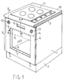
- a domestic oven comprises a body 1 of rectangular box shape supported on a base 2 and closed at the front by an oven panel or door 3, hinged at the bottom (by hinges 4, 5) to the body 1 so as to be releasable.
- the oven door 3 is constituted in known manner by an outer glass panel 6 and a metal inner support frame 7 which supports a removable inner glass window 8 separated from the outer panel by a heat-insulating cavity.
- the oven door 3 differs from those in known domestic ovens in that it extends up to the top 9 of the body of the oven which generally bears a continuous work surface 10, shown in section, of a modular kitchen unit.
- a gas or electric hob 11, in itself entirely conventional, may be fitted into the work surface 10 or may form part of the oven itself and be fixed to the body 1.
- the oven door 3 thus covers the front control panel of the oven where the knobs 12, 13 are arranged for controlling a timer and a thermostatic regulator respectively, and possibly other devices (oven light, grill, spit).
- control knobs 12, 13, housed in the thickness of the oven door are operable when the oven door is open but are also accessible through apertures in the oven door so they can be operated even when the door is closed.
- knobs are of the bi-stable or push-pull type so that, if pressure is exerted on them, they slide axially along their axes of rotation and project a convenient distance, of the order of 15-20mm, from the outer surface of the door 3 so that they can be gripped and turned even when the oven door is closed.
- the extension of the door 3 to the top of the oven 1 enables a monitoring window to be provided in the door 3 which also extends upwardly, as illustrated, thereby giving an easy view of the inner chamber of the oven.
- the broken line 14 indicates the upper edge of the door of a conventional domestic oven while the broken line 15 represents the upper edge of the monitoring window, again in a conventional oven.
- the front of the oven forms a single, homogeneous unit, without the break constituted by the gap between the door and the control panel.
- the handle of the door 3 is advantageous, but not essential, for the handle of the door 3 to be integral with the front glass panel 6, it being formed as an elongate aperture 16 therein, located so as to face a convenient recess in the control panel which is sufficiently wide and deep for the fingers of a hand to be able to grasp the upper or lower edge of the aperture 16, thus ensuring that the handling position is away from the hottest region.
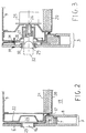
- Figure 2 shows a section through part of the body 1 and part of the overlying oven door 3 in order better to illustrate the structure thereof.
- the door is constituted by an outer glass panel 6 fixed by glue and/or engagement in a frame to a metal inner frame 7 suitably shaped to correspond with the oven opening so as to form a support for a resilient seal 17 and for a glass inner panel 8.
- a heat insulating cavity is formed between the outer panel 6 and the frame 7 or the inner panel 8 which can be partly filled with thermally-insulating material but with a window left free for the monitoring of the cooking chamber 19.
- This latter is defined by an internal wall 20 of the oven, the outer face of which is covered with thermally-insulating material 21 and which extends upwardly to support a front control panel 22 which faces the upper portion of the door 3.
- control panel is bent inwardly to form a housing 24 which enables the handle to be gripped easily.
- Figure 3 shows a detailed section of part of the door 3 which faces a control device, for example a thermostated switch 25, mounted in the control panel.
- a control device for example a thermostated switch 25, mounted in the control panel.
- the switch 25 which is conventional in itself, is mounted on the body of the oven, either directly on the inner wall 20 which is appropriately shaped or by means of support brackets, and has a control shaft 26 extending perpendicular to the front of the oven.
- An annular member 27 which forms a cavity is keyed to the shaft and has a peripheral indicator dial 28 coplanar with the control panel 22 and a knob 29, of the bistable push-button type, partially housed in the cavity of the annular member 27, the knob projecting suitably from the control panel and passing freely through an aperture in the outer panel 6 and the inner frame 7 of the door 3 so that its head is coplanar with the outer surface of the door 3 when this is closed.
- the aperture in the outer glass panel 6 which houses the knob 29 has a suitable plastic or metal seal 30, around its periphery.
- the knob 29 can be manipulated easily thanks to the cavity formed by the annular member which is large enough to receive the fingers of a user and give a comfortable and secure grip on the knob to allow the control device 25 to be set in a required condition identified by the correspondence of one of several indicators on the dial 28 with a fixed reference index 31 on the control panel.
- the knob can be manipulated even when the door is closed and the angular position of the dial 28 relative to a fixed reference index 33, printed on the glass panel 6, can be read through the glass.
- annular portion or at least a section of an annulus of the glass of the outer panel is left free of printing around the knob 29 and in this position the inner frame 7 of the door is suitably cut away.
- the various controls for the hotplates can be arranged on the front panel along with the oven controls.
- control panel it is not essential for the control panel to be positioned above the access opening to the oven with the door hinged at the bottom.
- control panel 41 can be positioned below the access aperture 42 and this may be closed by a door 43 which also extends over the control panel and is hinged at the top and pivots upwardly to open.
- the lower edge 44 of the front panel of the door which extends to the lower edge 45 of the oven body or just beyond it, can constitute a grip which enables the door to be opened or closed without the need to provide a handle-aperture in the panel.
- the lower front edge 45 of the body of the oven may be formed with a recess 46 to facilitate the grip, this recess being covered by the front door panel when the door is closed.
- the lower edge 44 of the front door panel may project conveniently beneath the lower front edge 45 of the oven body.
- This concept can also be applied in the case of an oven which is fitted into a conventional unit beneath a work surface or a hob.
Landscapes
- Engineering & Computer Science (AREA)
- Chemical & Material Sciences (AREA)
- Combustion & Propulsion (AREA)
- Mechanical Engineering (AREA)
- General Engineering & Computer Science (AREA)
- Electric Ovens (AREA)
- Electric Stoves And Ranges (AREA)
Applications Claiming Priority (2)
| Application Number | Priority Date | Filing Date | Title |
|---|---|---|---|
| ITMI950801 IT237294Y1 (it) | 1995-11-20 | 1995-11-20 | Forno domestico a pannello frontale continuo |
| ITMI950801U | 1995-11-20 |
Publications (3)
| Publication Number | Publication Date |
|---|---|
| EP0774626A2 true EP0774626A2 (fr) | 1997-05-21 |
| EP0774626A3 EP0774626A3 (fr) | 1999-04-07 |
| EP0774626B1 EP0774626B1 (fr) | 2002-09-11 |
Family
ID=11371390
Family Applications (1)
| Application Number | Title | Priority Date | Filing Date |
|---|---|---|---|
| EP19960201937 Expired - Lifetime EP0774626B1 (fr) | 1995-11-20 | 1996-07-10 | Four ménager à panneau frontal continu |
Country Status (3)
| Country | Link |
|---|---|
| EP (1) | EP0774626B1 (fr) |
| DE (1) | DE69623568T2 (fr) |
| IT (1) | IT237294Y1 (fr) |
Cited By (9)
| Publication number | Priority date | Publication date | Assignee | Title |
|---|---|---|---|---|
| DE10039445A1 (de) * | 2000-08-11 | 2002-02-28 | Bsh Bosch Siemens Hausgeraete | Backofentür |
| DE10059169A1 (de) * | 2000-11-29 | 2002-06-13 | Bsh Bosch Siemens Hausgeraete | Haushaltsgerät |
| FR2834332A1 (fr) * | 2001-12-27 | 2003-07-04 | Brandt Cooking | Four, notamment du type a micro-ondes, a esthetique amelioree |
| WO2007080038A1 (fr) * | 2006-01-10 | 2007-07-19 | BSH Bosch und Siemens Hausgeräte GmbH | Porte d'appareil ménager et module de commande associé |
| WO2007080037A1 (fr) * | 2006-01-10 | 2007-07-19 | BSH Bosch und Siemens Hausgeräte GmbH | Porte d'appareil de cuisson et module de commande associe |
| DE102007012378A1 (de) * | 2007-03-14 | 2008-09-18 | BSH Bosch und Siemens Hausgeräte GmbH | Hausgerät, insbesondere Backofen |
| CN108013848A (zh) * | 2016-10-28 | 2018-05-11 | 青岛海尔洗碗机有限公司 | 一种控制面板的集成结构及洗碗机 |
| IT201700118235A1 (it) * | 2017-10-19 | 2019-04-19 | Unipro S R L | Porta per un forno di tipo industriale per la cottura di cibi e forno comprendente tale porta |
| US10908762B2 (en) | 2015-07-20 | 2021-02-02 | Whirlpool Corporation | Household appliance closure element with touch interface |
Families Citing this family (2)
| Publication number | Priority date | Publication date | Assignee | Title |
|---|---|---|---|---|
| DE202004016052U1 (de) * | 2004-10-16 | 2006-02-23 | Diehl Ako Stiftung & Co. Kg | Backofen |
| DE102006001249B4 (de) * | 2006-01-10 | 2016-02-11 | BSH Hausgeräte GmbH | Gerätetür und Haushaltsgerät mit der Gerätetür |
Family Cites Families (5)
| Publication number | Priority date | Publication date | Assignee | Title |
|---|---|---|---|---|
| DE2701017C2 (de) * | 1977-01-12 | 1984-06-20 | Bosch-Siemens Hausgeräte GmbH, 7000 Stuttgart | Drehknebel für die Schalter von Haushaltgeräten |
| DE3151094C2 (de) * | 1981-12-23 | 1985-03-07 | Bosch-Siemens Hausgeräte GmbH, 7000 Stuttgart | Backofen |
| DE3435291A1 (de) * | 1984-09-26 | 1986-04-03 | Licentia Patent-Verwaltungs-Gmbh, 6000 Frankfurt | Versenkbarer drehknebel |
| IT215687Z2 (it) * | 1988-03-04 | 1990-10-22 | Zanussi A Spa Industrie | Piano di cottura con dispositivo di sicurezza d'alimentazione. |
| IT221773Z2 (it) * | 1991-03-27 | 1994-10-20 | Smeg Spa | Dispositivo comando dall'apertura di un forno domestico a gas per illuminare l'interno e per la contemporanea sicurezza all'ancensione elettronica. |
-
1995
- 1995-11-20 IT ITMI950801 patent/IT237294Y1/it active IP Right Grant
-
1996
- 1996-07-10 DE DE1996623568 patent/DE69623568T2/de not_active Expired - Lifetime
- 1996-07-10 EP EP19960201937 patent/EP0774626B1/fr not_active Expired - Lifetime
Cited By (13)
| Publication number | Priority date | Publication date | Assignee | Title |
|---|---|---|---|---|
| DE10039445C2 (de) * | 2000-08-11 | 2003-12-18 | Bsh Bosch Siemens Hausgeraete | Backofentür |
| DE10039445A1 (de) * | 2000-08-11 | 2002-02-28 | Bsh Bosch Siemens Hausgeraete | Backofentür |
| DE10059169A1 (de) * | 2000-11-29 | 2002-06-13 | Bsh Bosch Siemens Hausgeraete | Haushaltsgerät |
| FR2834332A1 (fr) * | 2001-12-27 | 2003-07-04 | Brandt Cooking | Four, notamment du type a micro-ondes, a esthetique amelioree |
| US8393319B2 (en) | 2006-01-10 | 2013-03-12 | Bsh Bosch Und Siemens Hausgeraete Gmbh | Domestic appliance door and pertaining operational module |
| WO2007080038A1 (fr) * | 2006-01-10 | 2007-07-19 | BSH Bosch und Siemens Hausgeräte GmbH | Porte d'appareil ménager et module de commande associé |
| WO2007080037A1 (fr) * | 2006-01-10 | 2007-07-19 | BSH Bosch und Siemens Hausgeräte GmbH | Porte d'appareil de cuisson et module de commande associe |
| CN101356407B (zh) * | 2006-01-10 | 2012-10-10 | Bsh博施及西门子家用器具有限公司 | 家用电器门以及附属的操作模块 |
| DE102007012378A1 (de) * | 2007-03-14 | 2008-09-18 | BSH Bosch und Siemens Hausgeräte GmbH | Hausgerät, insbesondere Backofen |
| US10908762B2 (en) | 2015-07-20 | 2021-02-02 | Whirlpool Corporation | Household appliance closure element with touch interface |
| US11622665B2 (en) | 2015-07-20 | 2023-04-11 | Whirlpool Corporation | Household appliance closure element with touch interface |
| CN108013848A (zh) * | 2016-10-28 | 2018-05-11 | 青岛海尔洗碗机有限公司 | 一种控制面板的集成结构及洗碗机 |
| IT201700118235A1 (it) * | 2017-10-19 | 2019-04-19 | Unipro S R L | Porta per un forno di tipo industriale per la cottura di cibi e forno comprendente tale porta |
Also Published As
| Publication number | Publication date |
|---|---|
| EP0774626A3 (fr) | 1999-04-07 |
| EP0774626B1 (fr) | 2002-09-11 |
| ITMI950801U1 (it) | 1997-05-20 |
| IT237294Y1 (it) | 2000-09-05 |
| DE69623568D1 (de) | 2002-10-17 |
| ITMI950801V0 (it) | 1995-11-20 |
| DE69623568T2 (de) | 2003-05-22 |
Similar Documents
| Publication | Publication Date | Title |
|---|---|---|
| EP0774626B1 (fr) | Four ménager à panneau frontal continu | |
| CA2344962C (fr) | Surface de cuisson ceramisee a tirage par le bas avec face avant inclinee | |
| USD513684S1 (en) | Backguard/control panel for a cooking appliance | |
| USD469304S1 (en) | Combination glass cooktop and plastic peripheral frame for a cooking appliance | |
| USD468961S1 (en) | Oven vent cover for a gas cooking appliance | |
| CN105485735B (zh) | 组合炉灶 | |
| JP3842026B2 (ja) | ビルトインコンロ | |
| USD511936S1 (en) | Oven door vent/handle assembly for a cooking appliance | |
| KR100718798B1 (ko) | 곤로 | |
| USD467768S1 (en) | Downdraft grill for a cooking appliance | |
| JPS64489Y2 (fr) | ||
| US11946649B2 (en) | Articulating mechanism for an appliance | |
| USD468159S1 (en) | Oven vent cover for a cooking appliance | |
| EP4271941A1 (fr) | Four avec dispositif de commande à bouton unique | |
| KR20100109105A (ko) | 조리기기용 도어 | |
| JP7792039B2 (ja) | 加熱調理器 | |
| KR200239627Y1 (ko) | 컨트롤 패널 개폐형 전자 렌지 | |
| US12050481B1 (en) | Systems for knob lockout on appliances | |
| CN217066085U (zh) | 厨具的锅盖和厨具 | |
| JP2005265237A (ja) | 電子レンジ | |
| JP4689368B2 (ja) | コンロ | |
| JPH0544946A (ja) | 加熱調理器 | |
| JPS60171322A (ja) | 加熱調理器の操作装置 | |
| JPH0355441A (ja) | 加熱調理器 | |
| JP4796908B2 (ja) | 誘導加熱調理器 |
Legal Events
| Date | Code | Title | Description |
|---|---|---|---|
| PUAI | Public reference made under article 153(3) epc to a published international application that has entered the european phase |
Free format text: ORIGINAL CODE: 0009012 |
|
| AK | Designated contracting states |
Kind code of ref document: A2 Designated state(s): DE FR GB IT |
|
| PUAL | Search report despatched |
Free format text: ORIGINAL CODE: 0009013 |
|
| AK | Designated contracting states |
Kind code of ref document: A3 Designated state(s): DE FR GB IT |
|
| 17P | Request for examination filed |
Effective date: 19990414 |
|
| GRAG | Despatch of communication of intention to grant |
Free format text: ORIGINAL CODE: EPIDOS AGRA |
|
| RTI1 | Title (correction) |
Free format text: A DOMESTIC OVEN WITH A CONTINUOUS FRONT PANEL |
|
| 17Q | First examination report despatched |
Effective date: 20011022 |
|
| GRAG | Despatch of communication of intention to grant |
Free format text: ORIGINAL CODE: EPIDOS AGRA |
|
| GRAH | Despatch of communication of intention to grant a patent |
Free format text: ORIGINAL CODE: EPIDOS IGRA |
|
| GRAH | Despatch of communication of intention to grant a patent |
Free format text: ORIGINAL CODE: EPIDOS IGRA |
|
| GRAA | (expected) grant |
Free format text: ORIGINAL CODE: 0009210 |
|
| AK | Designated contracting states |
Kind code of ref document: B1 Designated state(s): DE FR GB IT |
|
| REG | Reference to a national code |
Ref country code: GB Ref legal event code: FG4D |
|
| REF | Corresponds to: |
Ref document number: 69623568 Country of ref document: DE Date of ref document: 20021017 |
|
| ET | Fr: translation filed | ||
| PLBE | No opposition filed within time limit |
Free format text: ORIGINAL CODE: 0009261 |
|
| STAA | Information on the status of an ep patent application or granted ep patent |
Free format text: STATUS: NO OPPOSITION FILED WITHIN TIME LIMIT |
|
| 26N | No opposition filed |
Effective date: 20030612 |
|
| PGFP | Annual fee paid to national office [announced via postgrant information from national office to epo] |
Ref country code: FR Payment date: 20110810 Year of fee payment: 16 Ref country code: DE Payment date: 20110722 Year of fee payment: 16 Ref country code: GB Payment date: 20110721 Year of fee payment: 16 |
|
| PGFP | Annual fee paid to national office [announced via postgrant information from national office to epo] |
Ref country code: IT Payment date: 20110718 Year of fee payment: 16 |
|
| GBPC | Gb: european patent ceased through non-payment of renewal fee |
Effective date: 20120710 |
|
| REG | Reference to a national code |
Ref country code: FR Ref legal event code: ST Effective date: 20130329 |
|
| PG25 | Lapsed in a contracting state [announced via postgrant information from national office to epo] |
Ref country code: FR Free format text: LAPSE BECAUSE OF NON-PAYMENT OF DUE FEES Effective date: 20120731 Ref country code: GB Free format text: LAPSE BECAUSE OF NON-PAYMENT OF DUE FEES Effective date: 20120710 Ref country code: DE Free format text: LAPSE BECAUSE OF NON-PAYMENT OF DUE FEES Effective date: 20130201 |
|
| PG25 | Lapsed in a contracting state [announced via postgrant information from national office to epo] |
Ref country code: IT Free format text: LAPSE BECAUSE OF NON-PAYMENT OF DUE FEES Effective date: 20120710 |
|
| REG | Reference to a national code |
Ref country code: DE Ref legal event code: R119 Ref document number: 69623568 Country of ref document: DE Effective date: 20130201 |