EP0774629A2 - Chaudière à tubes d'eau et sa méthode de combustion - Google Patents
Chaudière à tubes d'eau et sa méthode de combustion Download PDFInfo
- Publication number
- EP0774629A2 EP0774629A2 EP96308379A EP96308379A EP0774629A2 EP 0774629 A2 EP0774629 A2 EP 0774629A2 EP 96308379 A EP96308379 A EP 96308379A EP 96308379 A EP96308379 A EP 96308379A EP 0774629 A2 EP0774629 A2 EP 0774629A2
- Authority
- EP
- European Patent Office
- Prior art keywords
- jet flames
- water tubes
- combustion chamber
- water
- combustion
- Prior art date
- Legal status (The legal status is an assumption and is not a legal conclusion. Google has not performed a legal analysis and makes no representation as to the accuracy of the status listed.)
- Granted
Links
Images


Classifications
-
- F—MECHANICAL ENGINEERING; LIGHTING; HEATING; WEAPONS; BLASTING
- F22—STEAM GENERATION
- F22B—METHODS OF STEAM GENERATION; STEAM BOILERS
- F22B31/00—Modifications of boiler construction, or of tube systems, dependent on installation of combustion apparatus; Arrangements or dispositions of combustion apparatus
-
- F—MECHANICAL ENGINEERING; LIGHTING; HEATING; WEAPONS; BLASTING
- F23—COMBUSTION APPARATUS; COMBUSTION PROCESSES
- F23D—BURNERS
- F23D14/00—Burners for combustion of a gas, e.g. of a gas stored under pressure as a liquid
- F23D14/20—Non-premix gas burners, i.e. in which gaseous fuel is mixed with combustion air on arrival at the combustion zone
- F23D14/22—Non-premix gas burners, i.e. in which gaseous fuel is mixed with combustion air on arrival at the combustion zone with separate air and gas feed ducts, e.g. with ducts running parallel or crossing each other
-
- F—MECHANICAL ENGINEERING; LIGHTING; HEATING; WEAPONS; BLASTING
- F23—COMBUSTION APPARATUS; COMBUSTION PROCESSES
- F23M—CASINGS, LININGS, WALLS OR DOORS SPECIALLY ADAPTED FOR COMBUSTION CHAMBERS, e.g. FIREBRIDGES; DEVICES FOR DEFLECTING AIR, FLAMES OR COMBUSTION PRODUCTS IN COMBUSTION CHAMBERS; SAFETY ARRANGEMENTS SPECIALLY ADAPTED FOR COMBUSTION APPARATUS; DETAILS OF COMBUSTION CHAMBERS, NOT OTHERWISE PROVIDED FOR
- F23M9/00—Baffles or deflectors for air or combustion products; Flame shields
- F23M9/10—Baffles or deflectors formed as tubes, e.g. in water-tube boilers
-
- F—MECHANICAL ENGINEERING; LIGHTING; HEATING; WEAPONS; BLASTING
- F24—HEATING; RANGES; VENTILATING
- F24H—FLUID HEATERS, e.g. WATER OR AIR HEATERS, HAVING HEAT-GENERATING MEANS, e.g. HEAT PUMPS, IN GENERAL
- F24H1/00—Water heaters, e.g. boilers, continuous-flow heaters or water-storage heaters
- F24H1/22—Water heaters other than continuous-flow or water-storage heaters, e.g. water heaters for central heating
- F24H1/40—Water heaters other than continuous-flow or water-storage heaters, e.g. water heaters for central heating with water tube or tubes
-
- F—MECHANICAL ENGINEERING; LIGHTING; HEATING; WEAPONS; BLASTING
- F23—COMBUSTION APPARATUS; COMBUSTION PROCESSES
- F23C—METHODS OR APPARATUS FOR COMBUSTION USING FLUID FUEL OR SOLID FUEL SUSPENDED IN A CARRIER GAS OR AIR
- F23C2900/00—Special features of, or arrangements for combustion apparatus using fluid fuels or solid fuels suspended in air; Combustion processes therefor
- F23C2900/06041—Staged supply of oxidant
-
- F—MECHANICAL ENGINEERING; LIGHTING; HEATING; WEAPONS; BLASTING
- F23—COMBUSTION APPARATUS; COMBUSTION PROCESSES
- F23C—METHODS OR APPARATUS FOR COMBUSTION USING FLUID FUEL OR SOLID FUEL SUSPENDED IN A CARRIER GAS OR AIR
- F23C2900/00—Special features of, or arrangements for combustion apparatus using fluid fuels or solid fuels suspended in air; Combustion processes therefor
- F23C2900/09002—Specific devices inducing or forcing flue gas recirculation
Definitions
- the present invention in particular, relates to a water tube boiler capable of reducing CO emission and a method for controlling combustion in the same.
- a water tube boiler which comprises a combustion chamber, a group of water tubes extending therethrough, and a burner for heating water passing through the group of water tubes by combustion gas to obtain hot water or steam.
- a large combustion zone is provided between the burner and the group of water tubes to sufficiently advance oxidation of CO into CO 2 , and then heat exchange is effected between the combustion gas and the group of the water tubes disposed on further down stream from the combustion zone. This is because if heat exchange were carried out prior to sufficient oxidation of CO contained in the combustion gas, a exhaust gas would contain residual CO in an undesirable amount. Accordingly, the volume of the combustion chamber is unavoidably large.
- the temperature of the flame is decreased in the first step by means of water tubes, and then CO is oxidized in the adiabatic space. It is thereby possible to realize a combustion chamber as a whole several times as small as a conventional combustion chamber and also realize low CO-generating combustion.
- the method and the apparatus effectively function as means for achieving low NOx/low CO-generating combustion when used in a water tube boiler utilizing a burner capable of producing flat flames which are uniform almost throughout a section of a combustion chamber and develop two-dimensional flows (see, for example, Japanese Unexamined Patent Publication No.229608/1995).
- it is required for realizing such low NOx/CO-generating combustion and for effectively utilizing the adiabatic space to generate flat flames spreading over the section of the combustion chamber.
- a premixed combustion system is often used to reduce a size of a combustion chamber.
- a pre-mixer is required to generate a premixture, and a safety device peculiar to premixed combustion is required to prevent back fire, explosion or the like.
- a diffusion flame burner having a relatively simple structure in terms of reduction in a cost of a burner, and easiness in manufacture and maintenance of a burner. It is also desired to attain low CO-generating combustion in a water tube boiler using a diffusion flame burner.
- the present inventors have conducted various combustion experiments using diffusion flame burners to solve the above problems, and through the experiments, they have experienced that if use is made of, in a water tube boiler, a burner whose burner ports are located only at such positions as to provide jet flames each localized in a cross-section of a combustion chamber of the water tube boiler, the jet flames are rapidly cooled by water tubes to prevent CO oxidation reaction from satisfactorily proceeding, and accordingly, the size of the combustion chamber is unavoidably large so as to surely provide a sufficient combustion zone.
- an object of the present invention to provide a water tube boiler of such a type that it uses a diffusion flame burner with burner ports located only at particular positions in a burner mounting wall of a combustion chamber to generate jet flames, which has a novel structure capable of realizing a size-reduced combustion chamber and capable of continuously effecting stable low CO-generating combustion.
- reference number 1 represents a combustion chamber having a rectangular section.
- a burner 2 is mounted in one end la of the combustion chamber 1, and a multiplicity of water tubes 3 are inserted through the combustion chamber 1 in the proximity of the burner 2.
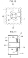
- Figure 9 is an enlarged sectional view showing the burner 2 and a portion of the combustion chamber 1 in the vicinity thereof.
- Figure 10 is a sectional view taken along the line X-X in Figure 9.
- Figure 11 is a fragmentary enlarged sectional view of the burner 2 taken along the line XI-XI in Fig.10.
- the burner 2 comprises a burner casing 21, an air pipe 22 having an inner diameter of D and disposed in the burner casing 21, a fuel pipe 10 inserted through the air pipe 22 coaxially therewith, a shielding plate 23 which contacts with the inside surface of the air pipe 22 and through which the fuel pipe 10 extends into the combustion chamber 1 having a section of 2D square, and a circular plate 24 attached to the front end of the fuel pipe 10.
- the shielding plate 23 are provided with four slot-like portions 25 at angular intervals of 90 degrees, each of which functions as an air injection portion.
- the fuel pipe 10 is provided with four fuel injection nozzles 26 adjacent to the shielding plate 23 which extend toward proximal edges of the slot-like portions 25.
- the tips 27 of the injection nozzles 26 are located in close vicinity of the proximal edges of the respective slot-like portions 25.
- the circular plate 24 has such a size that it is substantially inscribed in the proximal edges of the slot-like portions 25 when viewed in the axial direction of the fuel pipe 10.
- the burner 2 constructed as described above is mounted on the combustion chamber 1 in such a manner that the slot-like portions 25 formed in the shielding plate 23 are arranged on the diagonal lines of the 2D square cross-section of the combustion chamber 1.
- the burner 2 is described in detail in Japanese Patent Application No.106878 filed in the name of the applicant who is the same entity as the assignee (applicant) of the present application.
- air from the air pipe 22 and a fuel gas from the fuel injection nozzle 26 are supplied from the four slot-like portions 25 adjacent to the one end la of the combustion chamber 1, and the fuel gas initiates combustion forming flame 4 not stabilized at the slot-like portions 25 generating through the group of water tubes 3 to effect heat exchange between the flame 4 and the water tubes 3.
- the burner 2 was mounted on the water tube boiler at a distance L from the water tubes 3, i.e., at a standard position.
- the experiment was conducted using the burner 2 at a combustion rate of 28x10 4 kcal/h, and CO content of the resulting exhaust gas was measured.
- a combustion chamber which was altered so as to prolong the distance between the burner 2 and the water tubes 3 by about 60%, i.e., from L to 1.6L, the same experiment was conducted.
- the prolonged amount corresponds to about 20% of the visible flame length.
- the results are shown in Fig.12.
- the present inventor has further proceeded with experimental researches and consequently found that not by the mode where a prolonged CO oxidation reaction zone is provided on the upper side of water tubes but by providing a space empty of water tubes in the domain of a group of water tubes, which extends through the domain in the direction of jet flames, CO content of an exhaust gas is greatly reduced without enlarging a combustion chamber.
- the present invention has been made on the basis of the finding.
- the present invention provides a water tube boiler comprising:
- a water tube boiler comprising:
- the present invention provides a combustion method of a water tube boiler which has a combustion chamber and a group of water tubes extending therethrough and which generates jet flames at least through the group of water tubes to effect heat exchange, the method comprising:
- the group of water tubes are not uniformly distributed in a cross-section of the combustion chamber which is perpendicular to the direction of the jet flames but so arranged as to provide a portion thick with the water tubes and a portion empty of the water tubes, and at least empty portion continuously extends through the group of water tubes in the direction of the jet flames, i.e., it continuously extends through the group of water tubes in the direction of the jet flames.
- the jet flames when jet flames existing through the portion thick with water tubes are generated, the jet flames entrain a combustion gas having a high temperature which is present in the space as an empty portion continuously extending through the group of water tubes in the direction of the jet flames, thereby flowing downstream while entraining the combustion gas having a high temperature.
- rapid temperature decrease of the jet flames in the course of passage of the jet flames through the portion thick with the water tubes is prevented.
- the jet flames are thereby maintained in a CO oxidation promoting temperature range of about 1,000 to 1,500°C. Accordingly, oxidation reaction of CO into CO 2 satisfactorily proceeds. In other words, recirculation of the combustion gas is enhanced, and thus rapid temperature decrease of the jet flames passing through the group of water tubes is prevented to promote oxidation reaction of CO.
- the space as an empty portion may be provided at any position in a cross-section of the combustion chamber. To surely generate recirculating flows of a combustion gas having a high temperature, however, it is preferred that the space be provided at a position where at least a center of a jet flame does not pass through. Further, a space or a plurality of spaces may be provided in a cross-section of the combustion chamber. The space may be located at the center or at the positions adjacent to the opposite side walls in a cross-section of the combustion chamber.
- Figure 1 is an illustrative view showing one embodiment of the water tube boiler according to the present invention in plan.
- Figure 2 is an enlarged sectional view taken along the line II-II in Figure 1.
- Figure 3 is a graph showing CO-emission reductive results by means of the water tube boiler shown in Figure 1.
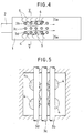
- Figure 4 is an illustrative view showing another embodiment of the water tube boiler according to the present invention in plan.
- Figure 5 is an enlarged sectional view taken along the line V-V in Figure 4.
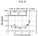
- Figure 6 is a graph showing CO-emission reductive results by means of the water tube boiler shown in Figure 4.
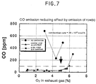
- Fig.7 is a comparative graph showing the CO-emission reductive effects.
- Fig.8 is an illustrative view showing a conventional water tube boiler in plan which was used in the experiments.
- Fig.9 is an enlarged sectional view showing the burner and a portion in the vicinity thereof.
- Fig.10 is a sectional view taken along the line X-X in Fig.9.
- Fig.11 is a fragmentary enlarged sectional view illustrating the burner used in the experiments, which is taken along the line XI-XI in Fig.10.
- Fig.12 is a graph showing CO emission by the water tube boilers of the type as shown in Fig.8.
- Fig.1 is an illustrative view showing one embodiment of the water tube boiler according to the present invention in plan.
- Fig.2 is an enlarged sectional view taken along the line II-II in Fig.1 and viewed upstream from the down stream of jet flames.
- the water tube boiler and the burner used therein which are illustrated in these Figs. are substantially the same as those described in the foregoing with reference to Figs.8 to 11 except that water tubes are arranged in a different manner, and therefore, like reference numbers are allotted to like parts to eliminate overlapping explanation.
- the distance between the water tubes 3 and the burner 2 is the same as that shown in Fig.8 (the burner is located at the standard position), and the distances between the water tubes are also the same as those in Fig.8. It is, however, to be noted that the water tubes are arranged in such a manner that of the water tubes in five rows in the water tube boiler shown in Fig.8, the center row of water tubes is omitted in whole.
- Figs. 4 and 5 show another embodiment of the water tube boiler according to the present invention.
- the two water tube rows 3a and 3e which are proximate to the side walls of the combustion chamber 1 are omitted.
- distances between one side wall of the combustion chamber and the row 3b, and between the row 3d and the other wall of the combustion chamber are large to provide "empty" portions
- the distances between the row 3b and the row 3c, and between the row 3c and the row 3d are small to provide a "thick" portion.
- the two vacancies along the side walls of the combustion chamber provide the "empty" portions which function as spaces Sa.
- recirculating flows 5 (shown by arrows) of combustion gas at a high temperature are generated as shown in Fig.4.
- the recirculating flows are entrained by the jet flames 4 running through the "thick" portion.
- Fig.6 shows results of combustion experiments which were carried out with three different combustion rates. As is apparent from Fig.6, also with this embodiment, the residual CO concentration of the exhaust gas in each case is in the main lower than 100ppm. The desired end is thereby achieved.
- Fig.7 is a graph showing the CO emission (ppm) at a combustion rate of 28x10 4 kcal/h which are extracted from the results in Figs.3, 6 and 12.
- the CO emission are greatly different between the cases where a row or rows of water tubes are omitted (water tube boiler provided with a space or spaces Sa capable of generating recirculating flows of combustion gas at a high temperature) and the case where no water tube is omitted (conventional water tube boiler), although the same combustion chamber and the same burner are used.
- the CO emission is in the main lower than 100ppm.
- the burner used is a new jet-flame burner according to the above-mentioned Japanese Patent Application which has previously been filed by the applicant who is the same entity as the applicant (assignee) of the present application. It is, however, to be noted that the burner is not restricted thereto, and that any burner may be used to attain substantially the same CO emission reducing effect so long as it is capable of producing a jet flame.
- the number and the position of the space Sa are not restricted to the space at the center position or the spaces at the positions adjacent to the opposite side walls of the combustion chamber. Depending upon the size of the combustion chamber, an appropriate number of spaces Sa may be provided at appropriate positions.
Landscapes
- Engineering & Computer Science (AREA)
- Chemical & Material Sciences (AREA)
- Combustion & Propulsion (AREA)
- Mechanical Engineering (AREA)
- General Engineering & Computer Science (AREA)
- Physics & Mathematics (AREA)
- Thermal Sciences (AREA)
Applications Claiming Priority (3)
| Application Number | Priority Date | Filing Date | Title |
|---|---|---|---|
| JP7301659A JPH09145001A (ja) | 1995-11-20 | 1995-11-20 | 水管式ボイラ及びその燃焼方法 |
| JP301659/95 | 1995-11-20 | ||
| JP30165995 | 1995-11-20 |
Publications (3)
| Publication Number | Publication Date |
|---|---|
| EP0774629A2 true EP0774629A2 (fr) | 1997-05-21 |
| EP0774629A3 EP0774629A3 (fr) | 1998-03-18 |
| EP0774629B1 EP0774629B1 (fr) | 2001-08-29 |
Family
ID=17899601
Family Applications (1)
| Application Number | Title | Priority Date | Filing Date |
|---|---|---|---|
| EP96308379A Expired - Lifetime EP0774629B1 (fr) | 1995-11-20 | 1996-11-19 | Chaudière à tubes d'eau et sa méthode de combustion |
Country Status (4)
| Country | Link |
|---|---|
| US (1) | US5894819A (fr) |
| EP (1) | EP0774629B1 (fr) |
| JP (1) | JPH09145001A (fr) |
| DE (1) | DE69614805T2 (fr) |
Cited By (1)
| Publication number | Priority date | Publication date | Assignee | Title |
|---|---|---|---|---|
| CN110793195A (zh) * | 2019-10-14 | 2020-02-14 | 北京航化节能环保技术有限公司 | 一种适用于低热值燃料低氧燃烧的热风炉设备 |
Families Citing this family (3)
| Publication number | Priority date | Publication date | Assignee | Title |
|---|---|---|---|---|
| US6289851B1 (en) | 2000-10-18 | 2001-09-18 | Institute Of Gas Technology | Compact low-nox high-efficiency heating apparatus |
| CN101644430B (zh) * | 2008-08-06 | 2011-01-26 | 于治华 | 一种扁管式完全预混高温燃气燃烧装置 |
| KR101224628B1 (ko) * | 2011-12-29 | 2013-01-22 | 한신보일러 주식회사 | 일산화탄소 저감형 관군 연소 보일러 |
Citations (2)
| Publication number | Priority date | Publication date | Assignee | Title |
|---|---|---|---|---|
| JPH0235884B2 (fr) | 1983-10-04 | 1990-08-14 | Tokyo Gas Co Ltd | |
| JPH07229608A (ja) | 1994-02-16 | 1995-08-29 | Ishikawajima Harima Heavy Ind Co Ltd | 多管式貫流ボイラ |
Family Cites Families (9)
| Publication number | Priority date | Publication date | Assignee | Title |
|---|---|---|---|---|
| US3638621A (en) * | 1969-08-26 | 1972-02-01 | Aqua Chem Inc | Combination fire and water tube boiler |
| US3791350A (en) * | 1972-08-03 | 1974-02-12 | Black Sivalls & Bryson Inc | Apparatus for heating fluids |
| JP3020505B2 (ja) * | 1988-07-26 | 2000-03-15 | 株式会社東芝 | 画像符号化装置、画像復号化装置および画像伝送装置 |
| US5273001A (en) * | 1988-12-22 | 1993-12-28 | Toshihiro Kayahara | Quadrangular type multi-tube once-through boiler |
| JPH02178502A (ja) * | 1988-12-29 | 1990-07-11 | Hirakawa Tekkosho:Kk | 水管群を有するボイラ |
| US5259342A (en) * | 1991-09-11 | 1993-11-09 | Mark Iv Transportation Products Corporation | Method and apparatus for low NOX combustion of gaseous fuels |
| JP3221582B2 (ja) * | 1992-09-09 | 2001-10-22 | 株式会社三浦研究所 | 低NOx、及び低CO燃焼装置 |
| JP2632635B2 (ja) * | 1993-02-25 | 1997-07-23 | 株式会社ヒラカワガイダム | 水管群を有するボイラの燃焼装置と該燃焼装置を使用するボイラの燃焼方法 |
| JP3454441B2 (ja) * | 1994-05-20 | 2003-10-06 | 東京瓦斯株式会社 | 窒素酸化物低発生燃焼方法及び装置 |
-
1995
- 1995-11-20 JP JP7301659A patent/JPH09145001A/ja active Pending
-
1996
- 1996-11-18 US US08/751,569 patent/US5894819A/en not_active Expired - Fee Related
- 1996-11-19 EP EP96308379A patent/EP0774629B1/fr not_active Expired - Lifetime
- 1996-11-19 DE DE69614805T patent/DE69614805T2/de not_active Expired - Fee Related
Patent Citations (2)
| Publication number | Priority date | Publication date | Assignee | Title |
|---|---|---|---|---|
| JPH0235884B2 (fr) | 1983-10-04 | 1990-08-14 | Tokyo Gas Co Ltd | |
| JPH07229608A (ja) | 1994-02-16 | 1995-08-29 | Ishikawajima Harima Heavy Ind Co Ltd | 多管式貫流ボイラ |
Cited By (1)
| Publication number | Priority date | Publication date | Assignee | Title |
|---|---|---|---|---|
| CN110793195A (zh) * | 2019-10-14 | 2020-02-14 | 北京航化节能环保技术有限公司 | 一种适用于低热值燃料低氧燃烧的热风炉设备 |
Also Published As
| Publication number | Publication date |
|---|---|
| DE69614805D1 (de) | 2001-10-04 |
| EP0774629A3 (fr) | 1998-03-18 |
| DE69614805T2 (de) | 2001-12-13 |
| JPH09145001A (ja) | 1997-06-06 |
| US5894819A (en) | 1999-04-20 |
| EP0774629B1 (fr) | 2001-08-29 |
Similar Documents
| Publication | Publication Date | Title |
|---|---|---|
| EP0801265B1 (fr) | Appareil à combustion | |
| DE60025933T2 (de) | Brennvorrichtung zur behandlung von abgas | |
| US4162140A (en) | NOx abatement in burning of gaseous or liquid fuels | |
| EP0376259B1 (fr) | Chaudière à basse émission de NOx | |
| RU2152559C2 (ru) | Способ и горелка для сжигания водорода | |
| EP0487052A2 (fr) | Incinérateur de déchets | |
| US5333597A (en) | Abatement member and method for inhibiting formation of oxides of nitrogen | |
| EP3414490B1 (fr) | Système de chauffage à combustion et procédé | |
| JPH01305206A (ja) | バーナー | |
| USRE33136E (en) | Burner for gas blow torch | |
| US5690039A (en) | Method and apparatus for reducing nitrogen oxides using spatially selective cooling | |
| US5181475A (en) | Apparatus and process for control of nitric oxide emissions from combustion devices using vortex rings and the like | |
| US6036475A (en) | Cyclonic type combustion apparatus | |
| EP3152490B1 (fr) | Appareil brûleur asymétrique à faible émission de nox et procédé | |
| EP0774629B1 (fr) | Chaudière à tubes d'eau et sa méthode de combustion | |
| US4013399A (en) | Reduction of gaseous pollutants in combustion flue gas | |
| US4157890A (en) | NOx abatement in gas burning where air is premixed with gaseous fuels prior to burning | |
| EP0003177B1 (fr) | Système de brûleur à gaz | |
| US7422427B2 (en) | Energy efficient low NOx burner and method of operating same | |
| JP4204202B2 (ja) | 燃焼装置 | |
| NL1011814C1 (nl) | Gas-oliecombinatiebrander van het niet-voorgemengde type. | |
| JP3071006B2 (ja) | ガスバーナー | |
| JPH0674409A (ja) | 燃焼ガス再循環機構を備えたボイラシステム | |
| WO2023035049A1 (fr) | Système de combustion à ultrafaibles émissions de nox et procédé de mélange rapide de combustible | |
| RU2040749C1 (ru) | Печь для нагрева труб |
Legal Events
| Date | Code | Title | Description |
|---|---|---|---|
| PUAI | Public reference made under article 153(3) epc to a published international application that has entered the european phase |
Free format text: ORIGINAL CODE: 0009012 |
|
| 17P | Request for examination filed |
Effective date: 19961202 |
|
| AK | Designated contracting states |
Kind code of ref document: A2 Designated state(s): DE FR GB NL |
|
| PUAL | Search report despatched |
Free format text: ORIGINAL CODE: 0009013 |
|
| AK | Designated contracting states |
Kind code of ref document: A3 Designated state(s): DE FR GB NL |
|
| 17Q | First examination report despatched |
Effective date: 20000310 |
|
| GRAG | Despatch of communication of intention to grant |
Free format text: ORIGINAL CODE: EPIDOS AGRA |
|
| GRAG | Despatch of communication of intention to grant |
Free format text: ORIGINAL CODE: EPIDOS AGRA |
|
| GRAH | Despatch of communication of intention to grant a patent |
Free format text: ORIGINAL CODE: EPIDOS IGRA |
|
| GRAH | Despatch of communication of intention to grant a patent |
Free format text: ORIGINAL CODE: EPIDOS IGRA |
|
| GRAA | (expected) grant |
Free format text: ORIGINAL CODE: 0009210 |
|
| AK | Designated contracting states |
Kind code of ref document: B1 Designated state(s): DE FR GB NL |
|
| REF | Corresponds to: |
Ref document number: 69614805 Country of ref document: DE Date of ref document: 20011004 |
|
| PG25 | Lapsed in a contracting state [announced via postgrant information from national office to epo] |
Ref country code: GB Free format text: LAPSE BECAUSE OF NON-PAYMENT OF DUE FEES Effective date: 20011129 |
|
| REG | Reference to a national code |
Ref country code: GB Ref legal event code: IF02 |
|
| EN | Fr: translation not filed | ||
| PG25 | Lapsed in a contracting state [announced via postgrant information from national office to epo] |
Ref country code: NL Free format text: LAPSE BECAUSE OF NON-PAYMENT OF DUE FEES Effective date: 20020601 |
|
| PG25 | Lapsed in a contracting state [announced via postgrant information from national office to epo] |
Ref country code: DE Free format text: LAPSE BECAUSE OF NON-PAYMENT OF DUE FEES Effective date: 20020702 |
|
| PLBE | No opposition filed within time limit |
Free format text: ORIGINAL CODE: 0009261 |
|
| STAA | Information on the status of an ep patent application or granted ep patent |
Free format text: STATUS: NO OPPOSITION FILED WITHIN TIME LIMIT |
|
| GBPC | Gb: european patent ceased through non-payment of renewal fee |
Effective date: 20011129 |
|
| NLV4 | Nl: lapsed or anulled due to non-payment of the annual fee |
Effective date: 20020601 |
|
| 26N | No opposition filed | ||
| ET | Fr: translation filed | ||
| REG | Reference to a national code |
Ref country code: FR Ref legal event code: ERR Free format text: BOPI DE PUBLICATION N: 02/04 PAGES: 243 PARTIE DU BULLETIN CONCERNEE: BREVETS EUROPEENS DONT LA TRADUCTION N'A PAS ETE REMISE A I'INPI IL Y A LIEU DE SUPPRIMER: LA MENTION DE LA NON REMISE. LA REMISE DE LA TRADUCTION EST PUBLIEE DANS LE PRESENT BOPI. |
|
| REG | Reference to a national code |
Ref country code: FR Ref legal event code: ST Effective date: 20080229 |
|
| PG25 | Lapsed in a contracting state [announced via postgrant information from national office to epo] |
Ref country code: FR Free format text: LAPSE BECAUSE OF NON-PAYMENT OF DUE FEES Effective date: 20011130 |