EP0774663B1 - Spectromètre de mobilité ionique - Google Patents
Spectromètre de mobilité ionique Download PDFInfo
- Publication number
- EP0774663B1 EP0774663B1 EP96113436A EP96113436A EP0774663B1 EP 0774663 B1 EP0774663 B1 EP 0774663B1 EP 96113436 A EP96113436 A EP 96113436A EP 96113436 A EP96113436 A EP 96113436A EP 0774663 B1 EP0774663 B1 EP 0774663B1
- Authority
- EP
- European Patent Office
- Prior art keywords
- ion mobility
- mobility spectrometer
- gas
- perforated disc
- diaphragm
- Prior art date
- Legal status (The legal status is an assumption and is not a legal conclusion. Google has not performed a legal analysis and makes no representation as to the accuracy of the status listed.)
- Expired - Lifetime
Links
- 239000007789 gas Substances 0.000 claims description 58
- 239000012159 carrier gas Substances 0.000 claims description 25
- 230000005291 magnetic effect Effects 0.000 claims description 9
- 238000006243 chemical reaction Methods 0.000 claims description 7
- 239000002184 metal Substances 0.000 claims description 7
- 239000011148 porous material Substances 0.000 claims description 7
- 239000000463 material Substances 0.000 claims description 3
- 239000011888 foil Substances 0.000 claims description 2
- 230000032258 transport Effects 0.000 claims description 2
- 230000010355 oscillation Effects 0.000 claims 6
- 230000005294 ferromagnetic effect Effects 0.000 claims 2
- 229910000831 Steel Inorganic materials 0.000 claims 1
- 239000010959 steel Substances 0.000 claims 1
- 239000012528 membrane Substances 0.000 description 48
- 150000002500 ions Chemical class 0.000 description 23
- 229920001296 polysiloxane Polymers 0.000 description 17
- 230000035945 sensitivity Effects 0.000 description 11
- 238000009792 diffusion process Methods 0.000 description 8
- 230000005284 excitation Effects 0.000 description 7
- 230000002285 radioactive effect Effects 0.000 description 7
- 230000000694 effects Effects 0.000 description 5
- 238000005259 measurement Methods 0.000 description 5
- 230000008901 benefit Effects 0.000 description 4
- 238000011084 recovery Methods 0.000 description 3
- 238000001228 spectrum Methods 0.000 description 3
- 239000000126 substance Substances 0.000 description 3
- 230000009471 action Effects 0.000 description 2
- 239000002575 chemical warfare agent Substances 0.000 description 2
- 238000004140 cleaning Methods 0.000 description 2
- 238000011161 development Methods 0.000 description 2
- 230000005684 electric field Effects 0.000 description 2
- 238000000034 method Methods 0.000 description 2
- 230000000737 periodic effect Effects 0.000 description 2
- 230000008569 process Effects 0.000 description 2
- 206010059875 Device ineffective Diseases 0.000 description 1
- XUIMIQQOPSSXEZ-UHFFFAOYSA-N Silicon Chemical compound [Si] XUIMIQQOPSSXEZ-UHFFFAOYSA-N 0.000 description 1
- 238000009825 accumulation Methods 0.000 description 1
- 239000003795 chemical substances by application Substances 0.000 description 1
- 238000011109 contamination Methods 0.000 description 1
- 230000004069 differentiation Effects 0.000 description 1
- 238000001035 drying Methods 0.000 description 1
- 238000001704 evaporation Methods 0.000 description 1
- 230000008020 evaporation Effects 0.000 description 1
- 238000002474 experimental method Methods 0.000 description 1
- 230000007246 mechanism Effects 0.000 description 1
- 239000000203 mixture Substances 0.000 description 1
- 239000002808 molecular sieve Substances 0.000 description 1
- 230000003534 oscillatory effect Effects 0.000 description 1
- 239000004033 plastic Substances 0.000 description 1
- 229920003023 plastic Polymers 0.000 description 1
- 238000012216 screening Methods 0.000 description 1
- 238000007789 sealing Methods 0.000 description 1
- 238000000926 separation method Methods 0.000 description 1
- 238000004904 shortening Methods 0.000 description 1
- 238000007873 sieving Methods 0.000 description 1
- 229910052710 silicon Inorganic materials 0.000 description 1
- 239000010703 silicon Substances 0.000 description 1
- 239000000779 smoke Substances 0.000 description 1
- URGAHOPLAPQHLN-UHFFFAOYSA-N sodium aluminosilicate Chemical compound [Na+].[Al+3].[O-][Si]([O-])=O.[O-][Si]([O-])=O URGAHOPLAPQHLN-UHFFFAOYSA-N 0.000 description 1
- 229910001220 stainless steel Inorganic materials 0.000 description 1
- 239000010935 stainless steel Substances 0.000 description 1
- 238000012549 training Methods 0.000 description 1
- XLYOFNOQVPJJNP-UHFFFAOYSA-N water Substances O XLYOFNOQVPJJNP-UHFFFAOYSA-N 0.000 description 1
Images


Classifications
-
- G—PHYSICS
- G01—MEASURING; TESTING
- G01N—INVESTIGATING OR ANALYSING MATERIALS BY DETERMINING THEIR CHEMICAL OR PHYSICAL PROPERTIES
- G01N27/00—Investigating or analysing materials by the use of electric, electrochemical, or magnetic means
- G01N27/62—Investigating or analysing materials by the use of electric, electrochemical, or magnetic means by investigating the ionisation of gases, e.g. aerosols; by investigating electric discharges, e.g. emission of cathode
- G01N27/622—Ion mobility spectrometry
Definitions
- the invention relates to an ion mobility spectrometer (IMS) with a measuring cell, consisting of a measuring arrangement and a housing that the measuring arrangement except for a gas inlet device gas-tight to the outside, whereby the gas inlet device in relation to the volume of the Measuring cell small amount from outside the housing Sample gas molecules through a perforated disc with a Allows pane thickness ⁇ 1 mm to flow into the interior of the housing, and a device for generating alternating positive and negative pressure gradients across the holes of the Washer on at least one side of the perforated washer is provided.
- IMS ion mobility spectrometer
- Such an ion mobility spectrometer is for example known from WO 93/01485, but there are no alternating ones Pressure gradient, but the successive application of either negative or positive pressure pulses a pinhole with a single needle-shaped central one Through hole with a diameter of 0.3 mm is proposed.
- the ion mobility spectrometer is a mass spectrometer, with the z. B. chemical warfare agents can be detected can. It works with a carrier gas at normal atmospheric Ambient pressure and therefore does not require a high vacuum.
- the runtime, the ionized molecules, is measured need to travel a certain distance (drift distance) pass through, which is filled with a carrier gas. The bigger the mobility of these molecules, the shorter the term through the carrier gas.
- This mobility is of the size of the Molecule and its chemical properties thus allows a differentiation of differently structured, ionized molecules.
- the gases to be examined are first analyzed using a radioactive source (usually beta emitters) ionized, so that they can then go on the drift route with an electric Field can be accelerated. At the end of They hit a collector electrode and drift path are electrically discharged and registered there. The fastest ions arrive first, slowest ones Enough. This creates a time spectrum similar to that of "Time of Flight" mass spectrometer (TOF mass spectrometer).
- a radioactive source usually beta emitters
- DMS silicone membrane
- the silicone membrane acts as a molecular diffusion pump, d. H. the molecules are transported through the membrane with the help of the diffusion effect. This is from the concentration gradient of the molecules between one and the other Side of the membrane. Is the focus on both Sides the same size, then the diffusion exchange disappears. In other words: as long as a diffusion exchange takes place, the concentration on the inside of the Membrane never has a higher concentration than on the outside to reach. This loses sensitivity, which has a very negative effect.
- a silicone membrane can be made with a very fine perforated sieve be compared.
- the function of the holes take over Interstices of the molecular tissue of the silicone.
- the holes are therefore very numerous, very small and moreover branches like a labyrinth, so that the holes become very long.
- the silicone membrane not only acts as a very fine perforated screen, but also as a sponge, in which molecules hang from gaps in the labyrinth remain and only with great effort, preferably through a cleaning process, can be removed again.
- a pinhole with a needle-shaped, central through hole developed to that of have negative pressure impulses on the inside of the device.
- This idea was first cited in the WO 93/01485 proposed and also described in WO 93/06476.
- a needle-shaped pinhole By attaching a needle-shaped pinhole on an otherwise hermetically sealed housing, and by generating negative pressure pulses inside of the housing, a meterable amount of the sample gas can outside through the panel into the reaction chamber of the IMS measuring arrangement be performed.
- the negative pressure pulse must be sufficient be large, so that the sample gas in the form of a laminar Beam flows out of the aperture and ends up in a stationary one Swirl ring merges.
- the diameter of the pinhole as well as the intensity and the Duration of the negative pressure pulse can be achieved that the vortex ring is transported into the ionization chamber, to be ionized there immediately.
- the use can now a molecular diffusion pump, e.g. B. in the form of a Silicone membrane, with all its disadvantages, can be avoided.
- the needle-shaped pinhole is a direct one Connection to the outside and prevents a complete hermetic closure of the measuring arrangement.
- the known pinhole is only needle-shaped, as long as the negative pressure impulses fail to appear, the outside area little Influence the interior. Also poses even a silicone membrane has no real hermetic seal because it has to be semi-permeable.
- a major disadvantage of the known gas inlet device with a small needle-shaped pinhole under the influence negative pressure pulses inside the measuring cell consists in that the device is extremely difficult to adjust and is very sensitive to the slightest changes in geometry, since it only works satisfactorily if precisely defined Flow conditions exist. Because of the very small Nozzle hole and because of the flow boundary conditions in negative pressure impulses limited in strength comes only a relative in the known gas inlet device ineffective mass transport. Because after the decay of a negative pressure pulse a subsequent post-flow time a carrier gas waited inside the measuring cell must therefore be the sample gas entry in the Measuring cell with the known device be very limited, overall resulting in a lower sensitivity of the IMS measuring arrangement leads.
- the object of the present invention is a Ion mobility spectrometer with the above
- a significantly lower Recovery time after each measuring pulse as an IMS apparatus Silicone membrane needed as a gas inlet device, on the other hand but much more robust in its operating behavior and is easier to adjust than an IMS measuring arrangement with needle-shaped pinhole under the influence of negative Pressure pulses and also a higher sample gas entry and thus a higher sensitivity to the known Has arrangements.
- the perforated disc consists of a non-porous material with a disc thickness between 10 microns and 1 mm and a plurality of through holes, preferably between 10 and 100 holes per cm 2 , which preferably have a diameter between Have 10 ⁇ m and 20 ⁇ m.
- the disc used according to the invention consists of a non-porous Material in which a variety of short, needle-shaped through holes is introduced the problem of spongy behavior like one Silicon membrane not from the outset, and the arrangement is immediately after each of the alternating pressure surges to measure.
- the perforated disc does not have the high one Screening effect and the good hermetic sealing properties a silicone membrane, however experiments show that this slight disadvantages in the IMS apparatus according to the invention of minor importance in the vast majority of applications are, whereas the advantages far outweigh.
- An embodiment of the invention is preferred Ion mobility spectrometer, in which the perforated disc made of metal, preferably of metal foil or thin sheet metal, for example stainless steel sheet.
- metal can also use any other non-porous material , but care must be taken that the surfaces do not give off any smoke like this for example, for some plastics their use significantly increases the sensitivity of the arrangement would be affected.
- the perforated disc be rigid, which is the advantage of a special great mechanical robustness and a simple, uncomplicated Built into the apparatus.
- ion mobility spectrometers are intended to the perforated disc along its circumferential edge vibrating membrane gas-tight connected to the housing and that the device for generating alternating Pressure gradient an active device Vibration excitation of the membrane includes.
- the membrane By own movement the membrane will mix even better Gas molecules reached on both sides of the perforated disc, causing a further increase in the concentration of the molecules inside the measuring arrangement and thus another Increased sensitivity results.
- One embodiment is particularly robust mechanically the device for generating alternating pressure gradients a piezoelectric oscillator for active Vibration excitation of the perforated disc includes.
- a piezoelectric oscillator for active Vibration excitation of the perforated disc includes.
- Such a piezoelectric oscillator is in many variations commercially available and very easy to get into one already Existing spectrometer can be installed.
- the Device for active vibration excitation of the membrane electromagnetic oscillator In another advantageous embodiment, the Device for active vibration excitation of the membrane electromagnetic oscillator.
- a preferred development of this embodiment draws is characterized in that the membrane preferably in its central area a permanent magnetic section, for example one or both sides of the membrane firmly applied layer of ferritic material, and that a preferably firmly connected to the housing electrical coil is provided with a electrical alternating current can be loaded and a magnetic Alternating field generated, which the membrane too Stimulates vibrations.
- Ion Mobility Spectrometer works for the facility active vibration excitation of the diaphragm on pneumatic Base.
- a alternating pump preferably a diaphragm pump
- the pump at the same time for pneumatic vibration excitation of the membrane serves.
- a membrane pump for circulating the carrier gas is present in this preferred embodiment no custom-made device for active Vibration excitation of the membrane to be installed. Therefore this embodiment is also from an economic point of view very cheap.
- the diaphragm pump preferably generates alternating pressure gradients in the frequency range between 10 Hz and 100 Hz, especially in a range between 30 Hz and 40 Hz, what for optimal mixing of the molecular concentration both sides of the membrane is completely sufficient.
- a particularly preferred embodiment of the invention distinguishes ion mobility spectrometers from that the carrier gas provided inside the housing is constantly circulated, and that the gas flow of the circulated Carrier gas is directed so that the carrier gas through the perforated disc into the interior of the sample gas molecules from the perforated disc into the reaction space transported to the measuring cell. This will make the sample gas concentration constantly degraded on the inside of the perforated disc and replaced by fresh sample gas entering from outside, which further increases the sensitivity of the arrangement.
- a thin-walled disk with a disk thickness between 10 ⁇ m and 1 mm made of a non-porous material with a plurality of through holes, preferably between 10 and 100 holes per cm 2 , which have a diameter between 5 ⁇ m and 50 um, preferably between 10 microns and 20 microns, for use in a gas inlet device of an ion mobility spectrometer according to the invention of the type described above.
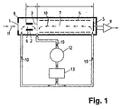
- FIG. 1 shows, in a schematic section, a housing 8 which seals the IMS measuring arrangement almost hermetically against the external environment.
- the only connection to the outside is through a gas inlet device with a perforated disk 1, which is constructed from non-porous material, has a disk thickness of 10 ⁇ m to 1 mm and a multiplicity of through holes, preferably between 10 and 100 holes per cm 2 , wherein the holes have a diameter between 5 microns and 50 microns, preferably between 10 microns and 20 microns.
- a radioactive source 2 is provided in the interior of the housing 8 following the gas inlet device and is located in a reaction chamber 6 at a potential of, for example, 2.2 kV.
- the radioactive source 2 will have a beta emitter (e.g. 63 Ni).
- the radioactive source 2 has the task of ionizing the measuring gas 11 entering the interior of the housing through the perforated disc 1, which is the actual measurement sample of the IMS apparatus and which can generally contain high-molecular chemical substances such as warfare agents.
- the potentials of the IMS measuring arrangement are chosen so that positive ions can be detected. In order to detect negative ions, only the polarity is required of voltages are switched.
- a Switching grid 3 in the measuring cell that in the example shown is at a potential of +1.6 kV and as a gate between the reaction space 6 and an adjoining one Drift room 7 works.
- the switching grid 3 controls the Passage of ionized molecules. It can consist of two separate ones Halves exist that are aligned in parallel Mesh bars mesh like a comb and (in the shown Example) are at an average potential of 1.6 kV. If there is a differential voltage across both halves of the switching grid of more than 100 V, so the electrical Field locally distorted, the ions are on the switching grid 3 discharged, and the switching grid 3 blocks the passage of Ions in the drift space 7. Is the differential voltage between the two halves of the grid are less than 100 V (usually 0 V), then the grid is permeable to the measuring ions.
- the drift space 7 adjoining the switching grid 3 there is an electrical gradient field, that of around the apparatus axis arranged around field electrodes 4 generated becomes.
- the field electrodes 4 have different voltage potentials, which in the case shown evenly between 1.6 kV and 0 V are distributed. That way in Drift space 7 accelerated electrical gradient field generated positive ions in front of the switching grid 3 to one at the end of the drift space 7 arranged collector electrode 5. As already mentioned, only needs to measure negative ions the polarity of all voltage potentials are switched.
- the radioactive Source 2 through the switching grid 3 and the subsequent Drift space 7 using the electrical gradient field from the field electrodes 4 accelerated gas ions collected and neutralizes their electrical charge. This will make a generates electrical signal that in a preamplifier 9 strengthened and then analyzed.
- the signal can but also in additional electronic units digitized, recorded in a microprocessor as a time spectrum and then analyzed in a more refined way.
- the carrier gas 10 With the help of a pump 12, generally a diaphragm pump, the carrier gas 10 is circulated in the measuring cell and through a filter 13 out. In this way, the carrier gas becomes 10 cleaned and dehumidified.
- the carrier gas 10 constantly circulated by means of the diaphragm pump 12 and through the filter 13 is performed, another important task can be performed are, namely the drying of the carrier gas.
- the filter 13 also absorbs the Collector electrode 5 neutralized ionized measuring molecules the measuring gas 11, which, as mentioned above, in many important applications for aggressive chemicals or chemical warfare agents, so it is recommended the contaminated filter 13 at regular intervals replaced.
- Ion mobility spectrometer plays the punched Window 1. It closes the closed interior of the housing 8 from the outside, but has a direct Connection to the outside. Thanks to the very small opening cross-sections however, one of the needle-shaped holes is created almost hermetic separation from the inside to the outside. The chemical Reactions inside the measuring cell are therefore avoided hardly influenced outside. It also works Disc 1 as a pressure-compensating element, which prevents that short-term pressure fluctuations in the outside the Influence measurement.
- a device for generating alternating positive and negative pressure gradients across the holes of the perforated Disk 1 contains the one on the right Perforated disc shown in plan view side of the figure 1 in its central area an evaporated or in other shape applied permanent magnetic layer 14, which contains, for example, ferritic material, and is firmly connected to the perforated disc 1.
- An electric one Coil 15 generates an alternating magnetic field in the kHz range, the one at the location of the magnetic layer 14 has strong field gradients. This will make a time variable force effect via the layer 14 on the perforated Disc 1 exercised, which the latter to swing brings.
- the disc 1 is as vibrating membrane formed along its circumferential Edge is gastight connected to the housing 8.
- Circulation pump 12 is a diaphragm pump that is used by nature from positive and negative pressure surges of the circulated anyway
- Carrier gas 10 (usually in the frequency range between 30 and 40 Hz), which are already sufficient to achieve a perforated disc 1 designed as a membrane in vibrations to move. If the carrier gas 10 on the inside of the perforated disc 1 is steered past, at the same time when circulating the carrier gas 10, the concentration of the ins Inside of the housing 8 penetrated measuring gas 11 on the inside the perforated disc 1 is constantly reduced, so that fresh gas 11 can penetrate from the outside.
- Figs. 3a to 3c is the mode of action of an oscillatory, perforated disc 1 in the form of a membrane shown.
- 3a shows the membrane in a stationary state. Since only the diffusion effect is effective, only a few molecules of the measurement gas 11 pass through the perforated Washer 1 from the outside into the interior of the housing 8. As soon as but the membrane vibrates, positive results on both sides and negative pressure gradients over the holes in the membrane, which move the gas molecules back and forth through the holes and whirl at the same time. This creates one uniform mixing of the molecules on both sides the perforated disc 1, as can be clearly seen in Fig. 3b is. This also results in a strong accumulation of molecules of the measuring gas 11 inside the housing 8.
- the latter could also be rigid be, for example, pneumatically generated periodically alternating positive and negative pressure fluctuations between on both sides of the perforated disc could. This would also result in the desired mixing of the gas molecules on both sides of the disc and thus one Increase in the concentration of the molecules to be measured on the inside the disc with the consequence of increasing the sensitivity the IMS equipment can be reached.
- the perforated disc 1 as a vibrating membrane but an even better mixing of the gas molecules Both sides of the membrane are made, resulting in another Increases the sensitivity of the equipment leads.
- the gas inlet device can also be used a conventional silicone membrane.
- Advantageous above all is the almost hermetic seal of the housing 8 to the outside. But that would be disadvantageous to accept the spongy behavior of the silicone membrane, but with the advantage of an increase described above the sensitivity by increasing the concentration of the Sample gas molecules still remains, however in more limited measure.
- Fig. 4 shows the ion current in pA as a function of Time in seconds when using a perforated membrane (A) or a conventional silicone membrane (B).
- A perforated membrane
- B conventional silicone membrane
Landscapes
- Chemical & Material Sciences (AREA)
- Physics & Mathematics (AREA)
- Life Sciences & Earth Sciences (AREA)
- Chemical Kinetics & Catalysis (AREA)
- Electrochemistry (AREA)
- Health & Medical Sciences (AREA)
- Spectroscopy & Molecular Physics (AREA)
- Analytical Chemistry (AREA)
- Biochemistry (AREA)
- General Health & Medical Sciences (AREA)
- General Physics & Mathematics (AREA)
- Immunology (AREA)
- Pathology (AREA)
- Other Investigation Or Analysis Of Materials By Electrical Means (AREA)
- Sampling And Sample Adjustment (AREA)
Claims (12)
- Spectromètre de mobilité ionique (SMI) comportant une cellule de mesuré composée d'un montage de mesure et d'un boítier (8) qui isole le montage de mesure de l'extérieur en le rendant étanche aux gaz à l'exception d'un dispositif d'entrée de gaz, dans lequel le dispositif d'entrée de gaz laisse passer dans l'intérieur du boítier, par un disque troué (1) d'une épaisseur ≤ 1 mm, une quantité de molécules de gaz de mesure (11) se trouvant à l'extérieur du boítier (8) faible par rapport au volume de la cellule de mesure, et dans lequel est prévu un dispositif pour générer, par l'intermédiaire des trous du disque (1), des gradients de pression positifs et négatifs alternants sur au moins un côté du disque troué (1),
caractérisé par le fait que le disque troué (1) est fait d'un matériau non poreux d'une épaisseur comprise entre 10 µm et 1 mm et présente un grand nombre de trous traversants, de préférence entre 10 et 100 trous par cm2, d'un diamètre compris entre 5 µm et 50 µm, de préférence entre 10 µm et 20 µm. - Spectromètre de mobilité ionique selon la revendication 1, caractérisé par le fait que le disque troué (1) est fait de métal, de préférence d'une feuille de métal ou d'une tôle fine, par exemple d'une tôle en acier spécial.
- Spectromètre de mobilité ionique selon l'une des revendications précédentes, caractérisé par le fait que le dispositif pour générer des gradients de pression alternants comprend un oscillateur piézoélectrique pour l'excitation en oscillation active du disque troué (1).
- Spectromètre de mobilité ionique selon l'une des revendications précédentes, caractérisé par le fait que le disque troué (1) possède une structure rigide.
- Spectromètre de mobilité ionique selon l'une des revendications 1 à 3, caractérisé par le fait que le disque troué (1) est une membrane oscillante reliée avec le boítier (8) d'une manière étanche aux gaz le long de son bord périphérique et que le dispositif pour générer des gradients de pression alternants comprend un dispositif pour l'excitation en oscillation active de la membrane.
- Spectromètre de mobilité ionique selon la revendication 5, caractérisé par le fait que le dispositif pour l'excitation en oscillation active de la membrane comprend un oscillateur électromagnétique.
- Spectromètre de mobilité ionique selon la revendication 6, caractérisé par le fait que la membrane présente, de préférence dans sa partie centrale, une section ferromagnétique, par exemple une couche de matériau ferromagnétique (14) appliquée à demeure sur une face ou sur les deux faces de la membrane, et qu'il est prévu une bobine électrique (15), de préférence solidaire du boítier (8), qui peut être alimentée par un courant électrique alternatif et génère un champ magnétique alternatif qui engendre des oscillations de la membrane.
- Spectromètre de mobilité ionique selon la revendication 7, caractérisé par le fait que la bobine électrique (15) peut générer un champ magnétique alternatif dans la gamme du kHz qui possède un gradient de champ à l'endroit de la section ferromagnétique de la membrane.
- Spectromètre de mobilité ionique selon la revendication 5, caractérisé par le fait que le dispositif pour l'excitation en oscillation active de la membrane fonctionne de manière pneumatique.
- Spectromètre de mobilité ionique selon la revendication 9, caractérisé par le fait qu'il est prévu une pompe (12) fonctionnant de manière alternante, de préférence une pompe à membrane pour la mise en circulation d'un gaz porteur (10) se trouvant à l'intérieur du boítier, et que la pompe (12) sert en même temps à l'excitation en oscillation pneumatique de la membrane.
- Spectromètre de mobilité ionique selon la revendication 10, caractérisé par le fait que la pompe (12) peut générer des gradients de pression alternants dans une gamme de fréquences comprise entre 10 Hz et 100 kHz, de préférence entre 30 Hz et 40 Hz.
- Spectromètre de mobilité ionique selon l'une des revendications précédentes, caractérisé par le fait qu'un gaz porteur (10) prévu à l'intérieur du boítier (8) est en circulation permanents et que le flux du gaz porteur (10) mis en circulation est guidé de telle manière que les molécules de gaz de mesure (11) qui ont pénétré à l'intérieur du boítier (8) à travers le disque troué (1) sont emportées par le gaz porteur (10) du disque troué (1) vers la chambre de réaction (6) de la cellule de mesure.
Applications Claiming Priority (2)
| Application Number | Priority Date | Filing Date | Title |
|---|---|---|---|
| DE19543159 | 1995-11-18 | ||
| DE19543159A DE19543159A1 (de) | 1995-11-18 | 1995-11-18 | Ionen-Mobilitäts-Spektrometer (IMS) |
Publications (2)
| Publication Number | Publication Date |
|---|---|
| EP0774663A1 EP0774663A1 (fr) | 1997-05-21 |
| EP0774663B1 true EP0774663B1 (fr) | 2002-11-20 |
Family
ID=7777877
Family Applications (1)
| Application Number | Title | Priority Date | Filing Date |
|---|---|---|---|
| EP96113436A Expired - Lifetime EP0774663B1 (fr) | 1995-11-18 | 1996-08-22 | Spectromètre de mobilité ionique |
Country Status (2)
| Country | Link |
|---|---|
| EP (1) | EP0774663B1 (fr) |
| DE (2) | DE19543159A1 (fr) |
Families Citing this family (11)
| Publication number | Priority date | Publication date | Assignee | Title |
|---|---|---|---|---|
| CA2289414A1 (fr) * | 1998-11-16 | 2000-05-16 | Henschel Wehrtechnik Gmbh | Vehicule pour l'analyse de melanges de substances, en particulier de melanges de polluants et d'agents chimiques a usage militaire |
| DE19860265A1 (de) * | 1998-12-24 | 2000-07-06 | Bruker Ag Faellanden | IMS-Membran mit gitterartiger Stützvorrichtung |
| DE10254960A1 (de) * | 2002-11-26 | 2004-06-09 | Gesellschaft zur Förderung der Spektrochemie und angewandten Spektroskopie e.V. | Miniaturisiertes Ionenbeweglichkeitsspektrometer |
| DE102005004325A1 (de) | 2005-01-31 | 2006-08-10 | Bruker Daltonik Gmbh | Ionenmobilitätsspektrometer und Verfahren zu seinem Betrieb |
| DE102007052802B4 (de) | 2007-11-06 | 2012-06-14 | Bruker Daltonik Gmbh | Ionenmobilitätsspektrometer und Verfahren zu seinem Betrieb |
| DE102007052801B4 (de) | 2007-11-06 | 2010-10-07 | Bruker Daltonik Gmbh | Ionenmobilitätsspektrometer mit Substanzsammler |
| CN101629933B (zh) * | 2008-07-16 | 2012-06-20 | 同方威视技术股份有限公司 | 离子迁移谱仪 |
| CN103245712A (zh) * | 2012-02-02 | 2013-08-14 | 上海新漫传感技术研究发展有限公司 | 一种基于离子迁移谱技术的化学战剂及工业有毒气体探测仪及其使用方法 |
| CN109524290B (zh) * | 2018-12-29 | 2025-04-18 | 同方威视技术股份有限公司 | 基于脉冲采样的离子迁移谱仪装置 |
| CN112103171B (zh) * | 2020-09-18 | 2023-10-13 | 中国科学院空天信息创新研究院 | 被动进样装置及应用 |
| GB2606571B (en) | 2021-05-14 | 2024-07-03 | Thermo Fisher Scient Bremen Gmbh | Ion mobility analyser |
Family Cites Families (7)
| Publication number | Priority date | Publication date | Assignee | Title |
|---|---|---|---|---|
| US4311669A (en) * | 1980-08-21 | 1982-01-19 | The Bendix Corporation | Membrane interface for ion mobility detector cells |
| US5345809A (en) * | 1989-06-09 | 1994-09-13 | Research Corporation Technologies, Inc. | Explosive detection screening system |
| CA1307715C (fr) * | 1989-09-28 | 1992-09-22 | Gavin Mcgregor | Limiteur de pression a disque de rupture |
| GB9115053D0 (en) * | 1991-07-12 | 1991-08-28 | Graseby Ionics Ltd | Fluid sampling system |
| US5162652A (en) * | 1991-08-07 | 1992-11-10 | Pcp, Inc. | Method and apparatus for rapid detection of contraband and toxic materials by trace vapor detection using ion mobility spectrometry |
| GB9120192D0 (en) * | 1991-09-21 | 1991-11-20 | Graseby Ionics Ltd | Ion mobility spectrometry equipment |
| US5455417A (en) * | 1994-05-05 | 1995-10-03 | Sacristan; Emilio | Ion mobility method and device for gas analysis |
-
1995
- 1995-11-18 DE DE19543159A patent/DE19543159A1/de not_active Ceased
-
1996
- 1996-08-22 EP EP96113436A patent/EP0774663B1/fr not_active Expired - Lifetime
- 1996-08-22 DE DE59609883T patent/DE59609883D1/de not_active Expired - Fee Related
Also Published As
| Publication number | Publication date |
|---|---|
| DE19543159A1 (de) | 1997-05-22 |
| EP0774663A1 (fr) | 1997-05-21 |
| DE59609883D1 (de) | 2003-01-02 |
Similar Documents
| Publication | Publication Date | Title |
|---|---|---|
| DE69927983T2 (de) | Verfahren zur trennung und anreicherung von isotopen in der gasphase | |
| EP0774663B1 (fr) | Spectromètre de mobilité ionique | |
| DE69219618T2 (de) | Coronaentladung-ionenquelle | |
| DE69629920T2 (de) | Massenspektrometer | |
| EP0497077B1 (fr) | Appareil pour la préparation d'échantillon à fins d'analyse | |
| DE102013114421B4 (de) | Gasanalyseeinrichtung und Verfahren zur Gasanalyse | |
| DE19609582C1 (de) | Photoionisations-Ionenmobilitätsspektrometrie | |
| DE69001719T2 (de) | Elektrostatischer Detektor von Aerosolen. | |
| DE19601054C1 (de) | Verfahren und Vorrichtung zur Bestimmung von Parametern von Partikeln in Elektrolyten | |
| DE69223878T2 (de) | Ionenbeweglichkeitspektrometer | |
| EP0233579A2 (fr) | Procédé et dispositif pour la détermination de petites quantités de gaz ou vapeurs dans des mélanges de gaz | |
| DE2934408A1 (de) | Ionenquelle mit kaltkathode und damit ausgeruestetes massenspektrometer | |
| DE69214950T2 (de) | System zur entnahme von flussigkeitsproben | |
| EP2428797A1 (fr) | Dispositif et procédé de détection et d'identification de gaz par spectrométrie de mobilité ionique | |
| DE4400420A1 (de) | Verfahren und Vorrichtung zum elektrostatischen Abscheiden von Verunreinigungen, wie Schwebstoffe oder dergleichen aus einem Gasstrom | |
| EP0848252A2 (fr) | Spectromètre à mobilité d'ions | |
| DE10061976A1 (de) | Anordnung und Verfahren zur quantitativen und qualitativen Analyse von Partikeln in Gasen | |
| DE19861106A1 (de) | Ionisierungskammer für ein Ionenmobilitätsspektrometer (IMS) | |
| DE4320607C2 (de) | Anordnung zur Spurengasanalyse | |
| DE1225897B (de) | Hochfrequenz-Massenspektrometer | |
| DE2363581A1 (de) | Verfahren zur zerstoerungsfreien chemischen analyse | |
| DE1673223A1 (de) | Verfahren und Vorrichtung zur Massen-Spektrometrie | |
| DE102022116682A1 (de) | Photo-Ionisations-Detektor (PID) mit mehreren Messzellen und Verfahren unter Verwendung eines solchen PIDs | |
| WO2010060905A1 (fr) | Dispositif pour collecter des particules à forte affinité électronique | |
| DE1698216A1 (de) | Massenspektrometer und Ionenmanometer |
Legal Events
| Date | Code | Title | Description |
|---|---|---|---|
| PUAI | Public reference made under article 153(3) epc to a published international application that has entered the european phase |
Free format text: ORIGINAL CODE: 0009012 |
|
| 17P | Request for examination filed |
Effective date: 19970217 |
|
| AK | Designated contracting states |
Kind code of ref document: A1 Designated state(s): CH DE FR GB LI |
|
| RAP1 | Party data changed (applicant data changed or rights of an application transferred) |
Owner name: BRUKER AG |
|
| 17Q | First examination report despatched |
Effective date: 19990304 |
|
| GRAG | Despatch of communication of intention to grant |
Free format text: ORIGINAL CODE: EPIDOS AGRA |
|
| GRAG | Despatch of communication of intention to grant |
Free format text: ORIGINAL CODE: EPIDOS AGRA |
|
| GRAH | Despatch of communication of intention to grant a patent |
Free format text: ORIGINAL CODE: EPIDOS IGRA |
|
| RAP1 | Party data changed (applicant data changed or rights of an application transferred) |
Owner name: BRUKER BIOSPIN AG |
|
| GRAH | Despatch of communication of intention to grant a patent |
Free format text: ORIGINAL CODE: EPIDOS IGRA |
|
| GRAA | (expected) grant |
Free format text: ORIGINAL CODE: 0009210 |
|
| AK | Designated contracting states |
Kind code of ref document: B1 Designated state(s): CH DE FR GB LI |
|
| REG | Reference to a national code |
Ref country code: GB Ref legal event code: FG4D Free format text: NOT ENGLISH |
|
| REG | Reference to a national code |
Ref country code: CH Ref legal event code: NV Representative=s name: TROESCH SCHEIDEGGER WERNER AG Ref country code: CH Ref legal event code: EP |
|
| REF | Corresponds to: |
Ref document number: 59609883 Country of ref document: DE Date of ref document: 20030102 |
|
| REG | Reference to a national code |
Ref country code: CH Ref legal event code: PUE Owner name: BRUKER DALTONICS GMBH Free format text: BRUKER BIOSPIN AG#INDUSTRIESTRASSE 26#8117 FAELLANDEN (CH) TRANSFER- BRUKER DALTONICS GMBH#INDUSTRIESTRASSE 26#8117 FAELLANDEN (CH) |
|
| REG | Reference to a national code |
Ref country code: GB Ref legal event code: 732E |
|
| RAP2 | Party data changed (patent owner data changed or rights of a patent transferred) |
Owner name: BRUKER DALTONICS GMBH |
|
| GBT | Gb: translation of ep patent filed (gb section 77(6)(a)/1977) |
Effective date: 20030326 |
|
| ET | Fr: translation filed | ||
| PLBE | No opposition filed within time limit |
Free format text: ORIGINAL CODE: 0009261 |
|
| STAA | Information on the status of an ep patent application or granted ep patent |
Free format text: STATUS: NO OPPOSITION FILED WITHIN TIME LIMIT |
|
| 26N | No opposition filed |
Effective date: 20030821 |
|
| REG | Reference to a national code |
Ref country code: GB Ref legal event code: 732E |
|
| REG | Reference to a national code |
Ref country code: CH Ref legal event code: PUE Owner name: BRUKER DALTONIK GMBH; FAHRENHEITSTRASSE 4; 28359 BREMEN (DE) Free format text: FORMER OWNER: BRUKER DALTONICS GMBH; INDUSTRIESTRASSE 26; 8117 FAELLANDEN (CH) |
|
| REG | Reference to a national code |
Ref country code: FR Ref legal event code: TP |
|
| PGFP | Annual fee paid to national office [announced via postgrant information from national office to epo] |
Ref country code: DE Payment date: 20080828 Year of fee payment: 13 |
|
| PGFP | Annual fee paid to national office [announced via postgrant information from national office to epo] |
Ref country code: FR Payment date: 20080827 Year of fee payment: 13 |
|
| PGFP | Annual fee paid to national office [announced via postgrant information from national office to epo] |
Ref country code: GB Payment date: 20080901 Year of fee payment: 13 |
|
| PGFP | Annual fee paid to national office [announced via postgrant information from national office to epo] |
Ref country code: CH Payment date: 20081024 Year of fee payment: 13 |
|
| REG | Reference to a national code |
Ref country code: CH Ref legal event code: PL |
|
| GBPC | Gb: european patent ceased through non-payment of renewal fee |
Effective date: 20090822 |
|
| PG25 | Lapsed in a contracting state [announced via postgrant information from national office to epo] |
Ref country code: LI Free format text: LAPSE BECAUSE OF NON-PAYMENT OF DUE FEES Effective date: 20090831 Ref country code: CH Free format text: LAPSE BECAUSE OF NON-PAYMENT OF DUE FEES Effective date: 20090831 |
|
| REG | Reference to a national code |
Ref country code: FR Ref legal event code: ST Effective date: 20100430 |
|
| PG25 | Lapsed in a contracting state [announced via postgrant information from national office to epo] |
Ref country code: FR Free format text: LAPSE BECAUSE OF NON-PAYMENT OF DUE FEES Effective date: 20090831 Ref country code: DE Free format text: LAPSE BECAUSE OF NON-PAYMENT OF DUE FEES Effective date: 20100302 |
|
| PG25 | Lapsed in a contracting state [announced via postgrant information from national office to epo] |
Ref country code: GB Free format text: LAPSE BECAUSE OF NON-PAYMENT OF DUE FEES Effective date: 20090822 |