EP0774884A2 - Detektor zur Erkennung einer defekten Lampe - Google Patents
Detektor zur Erkennung einer defekten Lampe Download PDFInfo
- Publication number
- EP0774884A2 EP0774884A2 EP96308257A EP96308257A EP0774884A2 EP 0774884 A2 EP0774884 A2 EP 0774884A2 EP 96308257 A EP96308257 A EP 96308257A EP 96308257 A EP96308257 A EP 96308257A EP 0774884 A2 EP0774884 A2 EP 0774884A2
- Authority
- EP
- European Patent Office
- Prior art keywords
- lamp
- voltage
- control
- failed
- dimmer circuit
- Prior art date
- Legal status (The legal status is an assumption and is not a legal conclusion. Google has not performed a legal analysis and makes no representation as to the accuracy of the status listed.)
- Withdrawn
Links
- 230000001419 dependent effect Effects 0.000 abstract 1
- 238000005259 measurement Methods 0.000 description 1
Images
Classifications
-
- H—ELECTRICITY
- H05—ELECTRIC TECHNIQUES NOT OTHERWISE PROVIDED FOR
- H05B—ELECTRIC HEATING; ELECTRIC LIGHT SOURCES NOT OTHERWISE PROVIDED FOR; CIRCUIT ARRANGEMENTS FOR ELECTRIC LIGHT SOURCES, IN GENERAL
- H05B47/00—Circuit arrangements for operating light sources in general, i.e. where the type of light source is not relevant
- H05B47/20—Responsive to malfunctions or to light source life; for protection
Definitions
- This invention relates to a failed light detector and in particular to a failed light detector of the type which can be used in a remotely controlled lighting system of the type proposed in our British patent application No. GB-A-2278473 and with a dimmable digital electronic ballast for lamp control such as the Trilux DD58.1-23031 electronic ballast.
- dimmable lights in such a control system.
- These, and conventional remotely controlled lights are usually operated by some form of digital electronic ballast such as are manufactured by Trilux Lighting Limited.
- the Trilux DD58.1-23031 is a dimmable digital electronic lamp ballast.
- Many digital electronic ballasts such as these provide a positive voltage level on their control input. The lamp is them dimmed by pulling the positive voltage line to a lower voltage. Alternatively the lamp may be dimmed by the application of a pulse waveform for example the Manchester code depending on the type of dimmer unit used.
- a pulse waveform for example the Manchester code depending on the type of dimmer unit used.
- the light that that digital electronic ballast is controlling fails the 10 volt output drops to zero. We have appreciated that this can be used to detect remotely whether or not a lamp has failed.
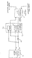
- the figure shows an addressable control module 2 of the type which would be used in a remotely controlled lighting system such as described in our British patent application No. GB-A-2278473.
- This receives input control signals from a central controller and sends these signals back to the central controller with the response to any status enquiry.
- This addressable control module is capable of responding to status enquiries and of switching and dimming a lamp.
- the addressable control is coupled to an analogue control unit 14 to control dimming of the light.
- the addressable control module sends signals 16 which are used to dim the light.
- the analogue control unit 16 is also used to check periodically whether or not the lamp has failed.
- a 0 to 10V control unit 18 which has 0 and 10 volt outputs.
- the 10 volt output is coupled via a reverse biased diode 20 to the positive voltage (in this case 10 volt) output of the dimmer control on a digital electronic lamp ballast 22.
- the 0 volt output of the control unit 18 is coupled to the 0 volt output of the lamp ballast. The lamp is dimmed by reducing the voltage level of the 10 volt output on the control unit 18.
- a comparator Also included in the analogue control unit 14 is a comparator.
- the two inputs to this are coupled across the reverse biased diode 20.
- the difference in the comparator inputs will be the diode voltage drop which may be, for example, 0.7V. This is taken as effectively zero difference and the comparator does not generate any output in response to this. In this situation the dimmer unit output is pulled to a voltage level less than 10V by the analogue control unit to dim the light.
- the comparator is used, whilst the lamp is in operation, to determine whether or not there has been a failure of the lamp. In order to do this the 10 volt output of the control unit 18 must be at a positive voltage and the lamp must be switched on. The comparator determines the difference in voltage across the diode. If the lamp is working the voltage measured will be the standard 0.7V drop across the diode. However, if the lamp has failed the voltage level between the diode 20 and the lamp ballast 22 will have dropped to zero. The comparator will therefore detect a voltage of opposite polarity to this 0.7V diode drop and equivalent to the output level of the analogue control unit. This is detected by the addressable control module and a lamp failure signal is output back to the central controller.
- the comparator can be operated continuously or at intervals to determine whether or not the lamp has failed. In the event that a failure is detected and transmitted to the central controller, an engineer can be sent to replace the lamp in question.
Landscapes
- Circuit Arrangement For Electric Light Sources In General (AREA)
Applications Claiming Priority (2)
| Application Number | Priority Date | Filing Date | Title |
|---|---|---|---|
| GB9523433A GB2307321A (en) | 1995-11-15 | 1995-11-15 | Failed light detector |
| GB9523433 | 1995-11-15 |
Publications (2)
| Publication Number | Publication Date |
|---|---|
| EP0774884A2 true EP0774884A2 (de) | 1997-05-21 |
| EP0774884A3 EP0774884A3 (de) | 1997-12-10 |
Family
ID=10783975
Family Applications (1)
| Application Number | Title | Priority Date | Filing Date |
|---|---|---|---|
| EP96308257A Withdrawn EP0774884A3 (de) | 1995-11-15 | 1996-11-15 | Detektor zur Erkennung einer defekten Lampe |
Country Status (2)
| Country | Link |
|---|---|
| EP (1) | EP0774884A3 (de) |
| GB (1) | GB2307321A (de) |
Cited By (1)
| Publication number | Priority date | Publication date | Assignee | Title |
|---|---|---|---|---|
| US6963170B2 (en) | 2002-03-01 | 2005-11-08 | Tapeswitch Ltd. | Lamp monitor and lamp |
Families Citing this family (1)
| Publication number | Priority date | Publication date | Assignee | Title |
|---|---|---|---|---|
| US9520742B2 (en) | 2014-07-03 | 2016-12-13 | Hubbell Incorporated | Monitoring system and method |
Citations (1)
| Publication number | Priority date | Publication date | Assignee | Title |
|---|---|---|---|---|
| GB2278473A (en) | 1993-05-26 | 1994-11-30 | Delmatic Ltd | Remote control systems |
Family Cites Families (8)
| Publication number | Priority date | Publication date | Assignee | Title |
|---|---|---|---|---|
| US3544803A (en) * | 1968-04-01 | 1970-12-01 | Motorola Inc | Vehicular electrical systems |
| DE2433025A1 (de) * | 1974-07-10 | 1976-01-22 | Bosch Gmbh Robert | Verfahren und vorrichtung zum steuern und kontrollieren von elektrischen schaltvorgaengen, insbesondere in kraftfahrzeugen |
| JPH0629116Y2 (ja) * | 1985-04-12 | 1994-08-10 | 株式会社東海理化電機製作所 | ランプの断線検出装置 |
| GB2174852B (en) * | 1985-05-02 | 1988-12-07 | Tann Electronics Ltd | Airfield lighting installations |
| DE4039161C2 (de) * | 1990-12-07 | 2001-05-31 | Zumtobel Ag Dornbirn | System zur Steuerung der Helligkeit und des Betriebsverhaltens von Leuchtstofflampen |
| FI95420C (fi) * | 1991-11-13 | 1997-05-14 | Heikki Korkala | Älykäs lamppu tai lampun älykäs liitäntäkanta |
| JP2600004Y2 (ja) * | 1992-09-16 | 1999-09-27 | 株式会社小糸製作所 | 車輌用放電灯の点灯回路 |
| GB2286891B (en) * | 1994-02-24 | 1997-12-17 | Strand Lighting Ltd | Dimmer fault reporting |
-
1995
- 1995-11-15 GB GB9523433A patent/GB2307321A/en not_active Withdrawn
-
1996
- 1996-11-15 EP EP96308257A patent/EP0774884A3/de not_active Withdrawn
Patent Citations (1)
| Publication number | Priority date | Publication date | Assignee | Title |
|---|---|---|---|---|
| GB2278473A (en) | 1993-05-26 | 1994-11-30 | Delmatic Ltd | Remote control systems |
Cited By (1)
| Publication number | Priority date | Publication date | Assignee | Title |
|---|---|---|---|---|
| US6963170B2 (en) | 2002-03-01 | 2005-11-08 | Tapeswitch Ltd. | Lamp monitor and lamp |
Also Published As
| Publication number | Publication date |
|---|---|
| GB9523433D0 (en) | 1996-01-17 |
| EP0774884A3 (de) | 1997-12-10 |
| GB2307321A (en) | 1997-05-21 |
Similar Documents
| Publication | Publication Date | Title |
|---|---|---|
| US6490512B1 (en) | Diagnostic system for an LED lamp for a motor vehicle | |
| US8258707B2 (en) | Lighting device with a LED used for sensing | |
| US7663323B2 (en) | Monitoring device for an array of electrical units | |
| EP1874098B1 (de) | Signalvorrichtung | |
| EP0390035A2 (de) | Apparat zur Überwachung der Beleuchtung | |
| CN113841466B (zh) | 用于led照明器的共享功率拓扑 | |
| US20150163878A1 (en) | Dimmable Lighting Systems and Methods of Dimming Lighting Systems | |
| JPH02287492A (ja) | Led素子の動作検出回路 | |
| EP0774884A2 (de) | Detektor zur Erkennung einer defekten Lampe | |
| US10939528B2 (en) | Electronic circuit with an LED module | |
| GB2404474A (en) | Emergency lighting monitoring system with lighting control | |
| CN1032942C (zh) | 火警系统 | |
| EP1787886B1 (de) | Elektrische Schaltung für LED Signallampen mit einer Schaltschwelle zum Umschalten zwischen Tages- und Nachtbetrieb | |
| KR102109045B1 (ko) | 차량용 직렬 엘이디 램프 고장 감지 후 엘이디 램프 밝기 유지 시스템 | |
| US20020101362A1 (en) | Backup traffic control in the event of power failure | |
| EP1781071B1 (de) | Regelung der Lichtintensität von LEDs hoher Leistung mittels der Eigenschaften des photoelektrischen Effekts dieser LEDs | |
| US7659671B2 (en) | High-reliability light fixture and method | |
| US10537008B2 (en) | Universal method for driving LEDs using high voltage | |
| KR100944876B1 (ko) | 엘이디 조명기구 제어시스템 | |
| JP4971076B2 (ja) | 照明調光システム | |
| CN116724665A (zh) | 控制和/或调节机构、电路布置结构、用于驱控发光二极管阵列中的发光二极管的方法 | |
| EP2201824B1 (de) | Schnittstelle für leuchtmittel -betriebsgerät | |
| US12557189B2 (en) | LED illuminator with automatic strobe mode and adjustable strobe intensity | |
| JP2008146836A (ja) | 照明装置 | |
| KR20110094250A (ko) | 적어도 하나의 조명 수단을 작동시키기 위한 회로 장치 |
Legal Events
| Date | Code | Title | Description |
|---|---|---|---|
| PUAI | Public reference made under article 153(3) epc to a published international application that has entered the european phase |
Free format text: ORIGINAL CODE: 0009012 |
|
| AK | Designated contracting states |
Kind code of ref document: A2 Designated state(s): BE DE ES FR GB |
|
| PUAL | Search report despatched |
Free format text: ORIGINAL CODE: 0009013 |
|
| AK | Designated contracting states |
Kind code of ref document: A3 Designated state(s): BE DE ES FR GB |
|
| 17P | Request for examination filed |
Effective date: 19980106 |
|
| STAA | Information on the status of an ep patent application or granted ep patent |
Free format text: STATUS: THE APPLICATION HAS BEEN WITHDRAWN |
|
| 18W | Application withdrawn |
Withdrawal date: 19990715 |