EP0774932B1 - Extracteur pneumatique de protheses dentaires - Google Patents
Extracteur pneumatique de protheses dentaires Download PDFInfo
- Publication number
- EP0774932B1 EP0774932B1 EP95928783A EP95928783A EP0774932B1 EP 0774932 B1 EP0774932 B1 EP 0774932B1 EP 95928783 A EP95928783 A EP 95928783A EP 95928783 A EP95928783 A EP 95928783A EP 0774932 B1 EP0774932 B1 EP 0774932B1
- Authority
- EP
- European Patent Office
- Prior art keywords
- disposed
- end unit
- compressed air
- valve
- adjustment ring
- Prior art date
- Legal status (The legal status is an assumption and is not a legal conclusion. Google has not performed a legal analysis and makes no representation as to the accuracy of the status listed.)
- Expired - Lifetime
Links
- 238000004891 communication Methods 0.000 claims abstract description 5
- 230000000994 depressogenic effect Effects 0.000 claims description 3
- 238000002347 injection Methods 0.000 abstract description 4
- 239000007924 injection Substances 0.000 abstract description 4
- 230000003213 activating effect Effects 0.000 abstract description 2
- 230000001105 regulatory effect Effects 0.000 abstract description 2
- 210000003254 palate Anatomy 0.000 description 6
- XLYOFNOQVPJJNP-UHFFFAOYSA-N water Substances O XLYOFNOQVPJJNP-UHFFFAOYSA-N 0.000 description 5
- 230000009471 action Effects 0.000 description 2
- 239000000853 adhesive Substances 0.000 description 2
- 230000001070 adhesive effect Effects 0.000 description 2
- 230000001276 controlling effect Effects 0.000 description 2
- 238000000605 extraction Methods 0.000 description 2
- 238000000034 method Methods 0.000 description 2
- 230000004048 modification Effects 0.000 description 2
- 238000012986 modification Methods 0.000 description 2
- 208000035473 Communicable disease Diseases 0.000 description 1
- 229910052782 aluminium Inorganic materials 0.000 description 1
- XAGFODPZIPBFFR-UHFFFAOYSA-N aluminium Chemical compound [Al] XAGFODPZIPBFFR-UHFFFAOYSA-N 0.000 description 1
- 230000005540 biological transmission Effects 0.000 description 1
- 239000002131 composite material Substances 0.000 description 1
- 230000001010 compromised effect Effects 0.000 description 1
- 230000000881 depressing effect Effects 0.000 description 1
- 238000013461 design Methods 0.000 description 1
- 238000011161 development Methods 0.000 description 1
- 208000015181 infectious disease Diseases 0.000 description 1
- 238000009434 installation Methods 0.000 description 1
- 239000004579 marble Substances 0.000 description 1
- 230000007246 mechanism Effects 0.000 description 1
- 229910052573 porcelain Inorganic materials 0.000 description 1
- 239000010970 precious metal Substances 0.000 description 1
- 230000008569 process Effects 0.000 description 1
- 238000009420 retrofitting Methods 0.000 description 1
- 229910001220 stainless steel Inorganic materials 0.000 description 1
- 239000010935 stainless steel Substances 0.000 description 1
- 230000001954 sterilising effect Effects 0.000 description 1
- 238000004659 sterilization and disinfection Methods 0.000 description 1
- 238000001356 surgical procedure Methods 0.000 description 1
Images



Classifications
-
- A—HUMAN NECESSITIES
- A61—MEDICAL OR VETERINARY SCIENCE; HYGIENE
- A61C—DENTISTRY; APPARATUS OR METHODS FOR ORAL OR DENTAL HYGIENE
- A61C3/00—Dental tools or instruments
- A61C3/16—Dentists' forceps or clamps for removing crowns
-
- A—HUMAN NECESSITIES
- A61—MEDICAL OR VETERINARY SCIENCE; HYGIENE
- A61C—DENTISTRY; APPARATUS OR METHODS FOR ORAL OR DENTAL HYGIENE
- A61C3/00—Dental tools or instruments
- A61C3/16—Dentists' forceps or clamps for removing crowns
- A61C3/164—Dentists' forceps or clamps for removing crowns acting by percussion
Definitions
- the present invention generally relates to an adjustable pneumatic remover and in particular to a device used to remove fabricated crowns and bridges from teeth restored in such a manner.
- the fabricated dental prosthetic usually formed from precious metals, porcelain, composite materials, or a combination, has proven to be a very functional and durable dental restoration, and is intended to be permanently affixed to the underlying tooth.
- dental prosthetics such as crowns, bridges and the like
- Prosthetics which are affixed via a strong adhesive are extremely difficult to remove and often require painful and time consuming surgery to aid in the extraction.
- the most widely accepted dental prosthetic remover is in the form of a pliers.
- pliers require the exertion of substantial force by the dentist which causes pain to the patient and often results in the damaging of the prosthetic device making it unusable for future restorations.
- the extractor device has a number of disadvantages. Firstly, the amount or flow of compressed air or strike intensity cannot be controlled via the device itself. That is, the air flow into the central portion of the extractor will be the same as the air flowing from the compressed air supply tank. It would be most desirable to be able to control the amount of compressed air that enters the extractor so as to provide for varied amounts of force (i.e., strike intensity) generated by the extractor during operation. Secondly, the use of a moving part such as a marble or ball in the air control valve can cause system failure due to misalignment or blockage of the air conduits.
- US-A-443 691 (30 December 1890) describes a dental plugger for giving a forward or backward blow, in which a flow adjusting means is provided in the outflow path.
- the present invention provides a pneumatic remover assembly as set forth in claim 1.
- the present invention enables one to overcome the inherent disadvantages of FR-A-2204966 by providing a remover device having a gentle, fingertip, push-button operation which is capable of providing the required striking intensity for crown or bridge removal.
- This steady strike action reduces slippage once the dental appliance is properly positioned about the prosthetic. Its minimal recoil action provides increased patient comfort, while sure and steady strikes reduce replacement costs.
- the present invention also provides a means for controlling the compressed air flow into the remover device which allows for preset, controlled uniformity of strike intensity which reduces damage to reusable crowns and bridges.
- the ability to control the air flowing into the remover also allows for its use in the removal of prosthetics with either temporary or permanent adhesives which necessitate different amounts of air flow or striking intensity to perform the function of removing the prosthesis from the tooth or gum.
- the remover may be readily connected to virtually any conventional two, three or four hole dental chair utility hose (compressed air port, vacuum port, water port and light port).
- the present invention may also provide many additional advantages which shall become apparent as described below.
- means for adjusting the flow rate of the compressed air or gas comprises an adjustment ring and a seventh conduit means disposed between the adjustment ring and the fifth conduit means.
- the adjustment ring comprises an airflow groove disposed about the surface of the adjustment ring which is in contact with the second end unit, the airflow groove has a gradually increasing depth along its length and is in communication with the seventh conduit means.
- a dental appliance for use in removing dental crowns and bridge from outside of the gum or palate may comprise an elongated stem portion and a means for gripping a dental prosthetic being disposed at about a 90° angle from the elongated stem portion.
- a dental appliance for use in removing dental crowns and bridge from inside of the gum or palate may comprise an elongated stem portion, a second stem portion disposed at an angle of about 17 degrees 30 minutes from the elongated stem portion, a third stem portion disposed at an angle of about 38 degrees from the elongated stem portion, and a means for gripping a dental prosthetic disposed at an angle of about 90 degrees from the third stem portion.
- a dental appliance for use in removing dental crowns and bridge located in the front of the mouth may comprise an elongated stem portion and a second stem portion disposed at an angle of about 16 degrees from the elongated stem portion.
- a pneumatic remover assembly having a central housing with a reciprocating internal mass or hammer and spring, a first end unit having a spool-type valve for activating the remover, a second end unit having various conduits disposed therein for introducing and exhausting compressed air in and out of the remover, and a unique adjustment ring which is capable of adjusting the flow rate of the compressed air which is introduced to the remover and, thus, controlling the striking intensity of the remover.
- the adjustment ring comprises an airflow groove disposed about the surface of the adjustment ring which is in contact with the second end unit of the remover assembly. This airflow groove has a gradually increasing depth along its length and is in continuous communication with the compressed air injection conduit disposed in the second end unit.
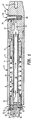
- Fig. 1 is a schematic representation of the pneumatic remover assembly according to the present invention
- Fig. 1 is in cross-section to permit clear description of the remover assembly 1.
- Pneumatic remover assembly 1 has a housing unit 3 which comprises an outer housing 5, a work chamber 7 disposed within outer housing 5, shaft member 9 centrally disposed within work chamber 7, an internal mass 11 reciprocally disposed about shaft member 9, and a spring means 13 disposed between internal mass 11 and a rear end of housing unit 3.
- Shaft member 9 includes a first conduit means 15 centrally disposed along its entire length which allows for passage of compressed air or gas therethrough.
- Pneumatic remover assembly 1 also includes a first end unit 17 disposed at an end of housing unit 3 such that internal mass 11 is disposed between spring means 13 and first end unit 17.
- First end unit 17 comprising a valve means 19, a means for securing 21 a dental appliance to first end unit 17, a second conduit means 23 for introducing the compressed air or gas from first conduit means 15 to valve means 19, a third conduit means 25 disposed within valve means 19 which is capable of passing the compressed air or gas from second conduit means 23 through valve means 19, and a fourth conduit means 27 for removing the compressed air or gas from valve means 19 and introducing the compressed air or gas into work chamber 7 where it is capable of acting on internal mass 11 by moving it away from first end unit 17.
- a second end unit 29 is disposed at the opposite end of housing unit 3 from first end unit 17 such that spring means 13 is disposed between second end unit 29 and internal mass 11.
- Second end unit 29 comprising a fifth conduit means 31 which is capable of introducing the compressed air or gas into first conduit means 15 of shaft member 9, at least one sixth conduit means 33 being capable of removing the compressed air or gas from work chamber 7 and out of assembly 1.
- Assembly 1 also include a means for adjusting the flow rate of the compressed air or gas which is introduced to pneumatic remover assembly 1 via fifth conduit means 31. Adjusting of the flow rate has a direct impact on the striking intensity applied to the respective dental prosthetic.
- the means for adjusting the flow rate of the compressed air or gas is an adjustment ring 35 and a seventh conduit means 37 disposed between adjustment ring 35 and fifth conduit means 31.
- adjustment ring 35 comprises an airflow groove 51 disposed about interior surface 53 of adjustment ring 35 which is in contact with second end unit 29.
- Airflow groove 51 has a gradually increasing depth along its length and is in communication with seventh conduit means 37.
- Airflow groove 51 has an exhaust notch or exit port 55 which is disposed near rear surface 57 of adjustment ring 35 which permits the compressed air to exit from assembly 1.
- adjustment ring 35 is secured about second end unit 29 by means of a spring 90 and pin 92 disposed within seat 94 of second end unit 29 and hole 52 disposed in adjustment ring 35.
- the rotational movement of adjustment ring 35 is controlled by means of a guide pin 56 disposed between a channel 58 of adjustment ring 35 and second end unit 29. It is the length of channel 58 which restricts the rotational movement of adjustment ring 35.
- valve means 19 comprises a valve housing 61, a valve stem or spool 63, and a spring 65, whereby third conduit means 25 which is disposed within valve means 19 is in the open position when valve stem 63 is depressed and in the closed position when valve stem 63 is returned to its normal position.
- Spring 65 and valve housing 61 are initially disposed within valve seat 24 shown in Fig. 2, followed by the placement of valve stem 63 inside of valve housing 61.
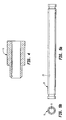
- Sixth conduit means 33 which is capable of removing the compressed air or gas from the center chamber is preferably a groove with a concave shape. Groove 33 is typically disposed along exterior surface 34 of second end unit 29 such that it is formed between exterior surface 34 and the interior surface of outer housing 5.
- Figs. 13-15 depict various unique dental appliances which are useful with remover assembly 1 according to the present invention.
- Each dental appliance is replaceably affixed to first end unit 17 by threaded means 21 for securing the dental appliance thereto.
- the dental appliance preferably has a threaded portion at one end thereof which is screwed into threaded means 21 for securing it to first end unit 17 of remover assembly 1.
- Fig. 13 depicts a dental appliance 71 for use in removing dental crowns and bridge from outside of the gum or palate.
- This dental appliance 71 comprises an elongated stem portion 73 and a means 75 for gripping a dental prosthetic being disposed at about a 90° angle from elongated stem portion 73.
- Fig. 14 is a dental appliance 77 for use in removing dental crowns and bridge from inside of the gum or palate.
- This dental appliance 77 comprises an elongated stem portion 79, a second stem portion 81 disposed at an angle of about 17 degrees 30 minutes from elongated stem portion 79, a third stem portion 83 disposed at an angle of about 38 degrees from elongated stem portion 79, and a means 85 for gripping a dental prosthetic disposed at an angle of about 90 degrees from second stem portion 81.
- Fig. 15 is a dental appliance 87 for use in removing dental crowns and bridge located in the front of the mouth.
- This dental appliance 87 comprises an elongated stem portion 89 and a second stem portion 91 disposed at an angle of about 16 degrees from elongated stem portion 89.
- pneumatic remover assembly 1 is connected to a conventional dental chair utility hose comprising 2, 3 or 4 basic dental utilities, i.e., compressed air, vacuum, water, or light.
- Figs. 1 and 7 depict a remover assembly 1 which is suitable for connection with a two utility dental hose (i.e., water and compressed air).
- the compressed air male injection port (not shown) is inserted into female port 32 such that the compressed air is capable of unrestrictedly entering conduit 31 of second end unit 29.
- the water male injection port (not shown) is inserted into dead-end female port 36 such that the water is incapable of entering conduit 31 or any interior portion of remover assembly 1.
- One of dental appliances (71, 77, 87) is selected depending upon the intended application and secured to first end unit 17 by screwing into threaded means 21
- the desired striking intensity and operating air pressure is determined using the conventional foot regulator
- the basic strike intensity is controlled with foot pedal pressure, while finer modification is regulated by rotation of adjustment ring 35 about second end unit 29 wherein reduced striking intensity is obtained by allowing more compressed air to pass through conduit 37, airflow groove 51 and notch 55. That is, the larger the depth of airflow groove 51 at the intersection with conduit 37, the more compressed air can exit via conduit 37.
- Increased striking intensity is therefore obtained by reducing the amount of compressed air which exits assembly 1 via conduit 37. In that instance, it would be desirable to have less depth in airflow groove 51 at the intersection with conduit 37. Conversely, if less striking intensity is desired, then a greater depth in airflow groove 51 at the intersection with conduit 37 would be required.
- the dental appliance For removal of a crown, the dental appliance (71, 77, 87) is positioned at the least sensitive point of the crown margin.
- the strike is delivered by depressing valve stem 63 such that compressed air from the dental chair utility hose enters conduit 31, a predetermined amount compressed air is diverted via conduit 37 and removed from assembly 1 via adjustment ring 35 to establish the desired striking intensity, and passes through conduit 15 of shaft means 9 where it enters conduit 23.
- valve stem 63 is depressed conduit 25 is opened such that compressed air passes therethrough into conduit 27
- the compressed air is carried along conduit 27 into work chamber 7 where it causes internal mass or hammer 11 to move toward second end unit 29, while spring 13 is compressed.
- Conduit 33 is preferably a plurality of grooves disposed about the exterior surface 34 of second end unit 29.
- extract assembly 1 be fabricated from either aluminum or stainless steel in order to permit sterilization thereof so as to avoid the transmission of infectious disease from patient to patient.
Landscapes
- Health & Medical Sciences (AREA)
- Oral & Maxillofacial Surgery (AREA)
- Dentistry (AREA)
- Epidemiology (AREA)
- Life Sciences & Earth Sciences (AREA)
- Animal Behavior & Ethology (AREA)
- General Health & Medical Sciences (AREA)
- Public Health (AREA)
- Veterinary Medicine (AREA)
- Dental Tools And Instruments Or Auxiliary Dental Instruments (AREA)
- Dental Preparations (AREA)
Claims (10)
- Système d'extraction pneumatique qui comprend :caractérisé par un moyen (35, 37) permettant de régler le débit de l'air comprimé ou du gaz comprimé qui est introduit dans le système d'extraction pneumatique par le biais du cinquième conduit (31) en empêchant une partie de l'air comprimé ou du gaz comprimé de pénétrer dans la chambre de travail (7).un bloc logement (3) qui comprend un logement extérieur (5), une chambre de travail (7), disposée à l'intérieur du logement extérieur (5), un arbre (9) disposé au centre de la chambre de travail (7), une masse interne (11) disposée réciproquement autour de l'arbre (9) et un ressort (13) disposé entre la masse interne (11) et une extrémité arrière du bloc logement (3), l'arbre (9) ayant un premier conduit (15) disposé sur toute sa longueur qui permet le passage d'air comprimé ou de gaz comprimé dans ledit conduit ;un premier bloc d'extrémité (17) disposé à une extrémité du bloc logement (3) de façon à ce que la masse interne (11) soit disposée entre le ressort (13) et le premier bloc d'extrémité (17), le premier bloc d'extrémité se composant d'une valve (19), d'un moyen (21) d'assujettir un appareil dentaire au premier bloc d'extrémité (17), d'un deuxième conduit (23) pour introduire l'air comprimé ou le gaz comprimé provenant du premier conduit (15) dans la valve (19), d'un troisième conduit (25) qui est disposé à l'intérieur de la valve (19) et qui est capable de faire passer l'air comprimé ou le gaz provenant du deuxième conduit (23) à travers la valve (19) et d'un quatrième conduit (27) pour extraire l'air comprimé ou le gaz comprimé de la valve (19) et introduire l'air comprimé ou le gaz comprimé dans la chambre de travail (7), où il est capable d'agir sur la masse interne (11) en l'éloignant du premier bloc d'extrémité (17) ; etun second bloc d'extrémité (29) disposé à l'extrémité opposée du bloc logement (3) par rapport au premier bloc d'extrémité (17) de façon à ce que le ressort (13) soit disposé entre le second bloc d'extrémité (29) et la masse interne (11), le second bloc d'extrémité (29) comprenant un cinquième conduit (31) qui est capable d'introduire l'air comprimé ou le gaz comprimé dans le premier conduit (15) de l'arbre (9), au moins un sixième conduit (33) étant capable d'extraire l'air comprimé ou le gaz comprimé de la chambre de travail (7) and du système dans son ensemble ;
- Système d'extraction pneumatique selon la revendication 1, où ledit moyen de réglage (35, 37) comprend un anneau de réglage (35) disposé autour du second bloc d'extrémité (29) et un septième conduit (37) disposé entre l'anneau de réglage (35) et le cinquième conduit (31).
- Système d'extraction pneumatique selon la revendication 2, où l'anneau de réglage (35) comprend une rainure de circulation de l'air (51) disposée sur la surface intérieure (53) de l'anneau de réglage qui est en contact avec le second bloc d'extrémité (29), la rainure de circulation de l'air (51) ayant une profondeur augmentant progressivement sur sa longueur et étant en communication avec le septième conduit (37).
- Système d'extraction pneumatique selon la revendication 3 comprenant également un orifice de sortie (55) connecté à une extrémité de la rainure de circulation de l'air (51) et disposé dans une surface extérieure (57) de l'anneau de réglage (35), de façon à ce que l'air comprimé ou le gaz comprimé qui passe à travers la rainure de circulation de l'air (51) puisse sortir de l'anneau de réglage (35) par le biais de l'orifice de sortie (55).
- Système d'extraction pneumatique selon la revendication 3 ou 4, où l'anneau de réglage (35) est disposé de façon mobile autour du second bloc d'extrémité (29) au moyen d'une broche de guidage (56) disposée à l'intérieur du second bloc d'extrémité et d'un canal (58) d'une longueur prédéterminée disposé dans une surface intérieure de l'anneau de réglage (35), permettant de faire tourner l'anneau de réglage par rapport à la broche de guidage (36) afin de contrôler la profondeur de la rainure de circulation de l'air (51) qui est disposée à l'opposé dudit septième conduit.
- Système d'extraction pneumatique selon l'une quelconque des revendications précédentes, où ladite valve (19) comprend un boítier de valve (61), une tige de valve (63) et un ressort de valve (65), de façon à ce que le troisième conduit (25), qui est disposé à l'intérieur de la valve (19), soit dans la position ouverte lorsque la tige de la valve (63) est enfoncée afin que le ressort de la valve (65) soit dans un état comprimé et dans la position fermée lorsque la tige de la valve (63) est remise dans sa position normale et lorsque le ressort de la valve (65) est dans un état déployé.
- Système d'extraction pneumatique selon l'une quelconque des revendications précédentes, où le sixième conduit (33), qui est capable d'extraire l'air comprimé ou le gaz comprimé de la chambre de travail, (7), consiste en une rainure disposée entre le second bloc d'extrémité (29) et le logement extérieur (5), la rainure étant formée sur la surface extérieure du second bloc d'extrémité (29).
- Système d'extraction pneumatique selon l'une quelconque des revendications 1 à 7, comprenant également un appareil dentaire (71) attaché au premier bloc d'extrémité (17) par ledit moyen d'assujettissement (21), l'appareil dentaire (71) comprenant une tige allongée (73) et un moyen (75) de saisie d'une prosthèse dentaire disposé à un angle d'environ 90 ° par rapport à la tige allongée (73).
- Système d'extraction pneumatique selon l'une quelconque des revendications 1 à 7, comprenant également un appareil dentaire (77) fixé au premier bloc d'extrémité (17) par ledit moyen d'assujettissement (21), l'appareil dentaire (77) comprenant une tige allongée (79), une deuxième tige (81) disposée à un angle d'environ 17 degrés 30 minutes par rapport à la tige allongée (79), une troisième tige (83) disposée à un angle d'environ 38 degrés par rapport à la tige allongée (79) et un moyen (85) de saisie d'une prosthèse dentaire disposé à un angle d'environ 90 ° par rapport à la deuxième tige (81).
- Système d'extraction pneumatique selon l'une quelconque des revendications 1 à 7, comprenant également un appareil dentaire (87) fixé au premier bloc d'extrémité (17) par ledit moyen d'assujettissement (21), l'appareil dentaire (87) comprenant une tige allongée (89) et une deuxième tige (91) disposée à un angle d'environ 16 degrés par rapport à la tige allongée (89).
Applications Claiming Priority (3)
| Application Number | Priority Date | Filing Date | Title |
|---|---|---|---|
| US08/292,808 US5496172A (en) | 1994-08-10 | 1994-08-10 | Pneumatic remover for use in removing dental prosthetics |
| US292808 | 1994-08-10 | ||
| PCT/US1995/010042 WO1996004863A1 (fr) | 1994-08-10 | 1995-08-08 | Extracteur pneumatique de protheses dentaires |
Publications (3)
| Publication Number | Publication Date |
|---|---|
| EP0774932A1 EP0774932A1 (fr) | 1997-05-28 |
| EP0774932A4 EP0774932A4 (fr) | 1999-03-17 |
| EP0774932B1 true EP0774932B1 (fr) | 2003-02-05 |
Family
ID=23126287
Family Applications (1)
| Application Number | Title | Priority Date | Filing Date |
|---|---|---|---|
| EP95928783A Expired - Lifetime EP0774932B1 (fr) | 1994-08-10 | 1995-08-08 | Extracteur pneumatique de protheses dentaires |
Country Status (9)
| Country | Link |
|---|---|
| US (1) | US5496172A (fr) |
| EP (1) | EP0774932B1 (fr) |
| JP (1) | JPH10503957A (fr) |
| AT (1) | ATE232066T1 (fr) |
| AU (1) | AU3241395A (fr) |
| BR (1) | BR9508585A (fr) |
| DE (1) | DE69529568T2 (fr) |
| ES (1) | ES2197206T3 (fr) |
| WO (1) | WO1996004863A1 (fr) |
Families Citing this family (5)
| Publication number | Priority date | Publication date | Assignee | Title |
|---|---|---|---|---|
| US5545038A (en) * | 1995-07-27 | 1996-08-13 | Sidney Horowitz | Percussive dental extractor |
| US6176703B1 (en) * | 1997-04-18 | 2001-01-23 | Kaltenbach & Voigt Gmbh & Co. | Medical or dental treatment instrument for chip-removing treatment of body tissue or a substitute material with an abrasive tool |
| JP3706360B2 (ja) * | 2002-07-12 | 2005-10-12 | 藤栄電気株式会社 | 歯牙動揺度測定装置、同装置の動作方法、及び同装置に使用されるノズル |
| US10617488B2 (en) * | 2014-05-23 | 2020-04-14 | Douglas Block | Dental prosthesis, apparatus and kit |
| CN109330717B (zh) * | 2018-09-27 | 2020-10-09 | 漯河市第一人民医院 | 一种拔牙器 |
Citations (1)
| Publication number | Priority date | Publication date | Assignee | Title |
|---|---|---|---|---|
| FR2204966A7 (fr) * | 1972-09-19 | 1974-05-24 | Toma Michele De |
Family Cites Families (10)
| Publication number | Priority date | Publication date | Assignee | Title |
|---|---|---|---|---|
| US443691A (en) * | 1890-12-30 | Dental plugger | ||
| US394464A (en) * | 1888-12-11 | Pneumatic dental plugger | ||
| US279928A (en) * | 1883-06-26 | Disteict | ||
| US419381A (en) * | 1890-01-14 | Frederick edward thomas and robert proudfoot lennox | ||
| US618324A (en) * | 1899-01-24 | Dental plugger | ||
| US2129212A (en) * | 1937-03-12 | 1938-09-06 | George M Hollenback | Dental device |
| US2598624A (en) * | 1947-10-23 | 1952-05-27 | Woude Philip J Van Der | Dental instrument |
| US4316465A (en) * | 1979-03-30 | 1982-02-23 | Dotson Robert S Jun | Ophthalmic handpiece with pneumatically operated cutter |
| US4300885A (en) * | 1980-07-30 | 1981-11-17 | George Khait | Percussive dental crown extractor |
| DE4318253A1 (de) * | 1993-06-02 | 1994-12-08 | Vladimir Iljic Dr Puchaev | Kronen- und Brückenabzieher |
-
1994
- 1994-08-10 US US08/292,808 patent/US5496172A/en not_active Expired - Lifetime
-
1995
- 1995-08-08 AT AT95928783T patent/ATE232066T1/de not_active IP Right Cessation
- 1995-08-08 AU AU32413/95A patent/AU3241395A/en not_active Abandoned
- 1995-08-08 DE DE69529568T patent/DE69529568T2/de not_active Expired - Fee Related
- 1995-08-08 JP JP8507444A patent/JPH10503957A/ja not_active Ceased
- 1995-08-08 EP EP95928783A patent/EP0774932B1/fr not_active Expired - Lifetime
- 1995-08-08 BR BR9508585-8A patent/BR9508585A/pt not_active IP Right Cessation
- 1995-08-08 WO PCT/US1995/010042 patent/WO1996004863A1/fr not_active Ceased
- 1995-08-08 ES ES95928783T patent/ES2197206T3/es not_active Expired - Lifetime
Patent Citations (1)
| Publication number | Priority date | Publication date | Assignee | Title |
|---|---|---|---|---|
| FR2204966A7 (fr) * | 1972-09-19 | 1974-05-24 | Toma Michele De |
Also Published As
| Publication number | Publication date |
|---|---|
| DE69529568T2 (de) | 2004-02-05 |
| DE69529568D1 (de) | 2003-03-13 |
| EP0774932A1 (fr) | 1997-05-28 |
| JPH10503957A (ja) | 1998-04-14 |
| US5496172A (en) | 1996-03-05 |
| AU3241395A (en) | 1996-03-07 |
| EP0774932A4 (fr) | 1999-03-17 |
| BR9508585A (pt) | 2001-07-31 |
| ES2197206T3 (es) | 2004-01-01 |
| WO1996004863A1 (fr) | 1996-02-22 |
| ATE232066T1 (de) | 2003-02-15 |
Similar Documents
| Publication | Publication Date | Title |
|---|---|---|
| EP0726737B1 (fr) | Systeme de traitement dentaire | |
| US5297962A (en) | Dental cleaning device | |
| EP0634914B1 (fr) | Systeme de traitement dentaire | |
| AU674706B2 (en) | Portable sterilizable water supply for dental appliances | |
| US6004191A (en) | Particulate matter delivery device | |
| KR20120099679A (ko) | 에어 워터 진공 실린지 및 그 사용 방법 | |
| GB1594062A (en) | Dental handpiece | |
| JP2004536661A (ja) | 歯科用サンドブラスト具 | |
| US7021932B2 (en) | Tooth extraction device | |
| AU2001242353A1 (en) | Rinsing cannula for rinsing a root canal of a tooth | |
| US20020016137A1 (en) | Hand-holdable gas/abrasion apparatus | |
| US5496172A (en) | Pneumatic remover for use in removing dental prosthetics | |
| US5234338A (en) | Autoclavable head and handle for dental syringe | |
| US5941702A (en) | Air-abrading tool | |
| US6638068B2 (en) | Medical handpiece having a rod-shaped grip part | |
| EP1025809A2 (fr) | Piéce à main dentaire protégée contre la contamination | |
| US3250005A (en) | Dental tool and control apparatus | |
| US5545038A (en) | Percussive dental extractor | |
| JP4752079B2 (ja) | 歯科用バキュームハンドピース | |
| US3256603A (en) | Dental tool and handpiece control | |
| US5261816A (en) | Dental handpiece coolant delivery system | |
| AU2009203099B2 (en) | Dental Handpiece Fluid Supply Technology | |
| WO2005041805A2 (fr) | Piece a main dentaire | |
| US20160317248A1 (en) | Dental appliance removal tool and methods of use | |
| JPH11235351A (ja) | レーザ装置用のハンドピース |
Legal Events
| Date | Code | Title | Description |
|---|---|---|---|
| PUAI | Public reference made under article 153(3) epc to a published international application that has entered the european phase |
Free format text: ORIGINAL CODE: 0009012 |
|
| 17P | Request for examination filed |
Effective date: 19970220 |
|
| AK | Designated contracting states |
Kind code of ref document: A1 Designated state(s): AT CH DE ES FR GB IT LI |
|
| A4 | Supplementary search report drawn up and despatched |
Effective date: 19990203 |
|
| AK | Designated contracting states |
Kind code of ref document: A4 Designated state(s): AT CH DE ES FR GB IT |
|
| RBV | Designated contracting states (corrected) |
Designated state(s): AT CH DE ES FR GB IT LI |
|
| 17Q | First examination report despatched |
Effective date: 20011005 |
|
| GRAH | Despatch of communication of intention to grant a patent |
Free format text: ORIGINAL CODE: EPIDOS IGRA |
|
| GRAH | Despatch of communication of intention to grant a patent |
Free format text: ORIGINAL CODE: EPIDOS IGRA |
|
| GRAA | (expected) grant |
Free format text: ORIGINAL CODE: 0009210 |
|
| AK | Designated contracting states |
Designated state(s): AT CH DE ES FR GB IT LI |
|
| PG25 | Lapsed in a contracting state [announced via postgrant information from national office to epo] |
Ref country code: LI Free format text: LAPSE BECAUSE OF FAILURE TO SUBMIT A TRANSLATION OF THE DESCRIPTION OR TO PAY THE FEE WITHIN THE PRESCRIBED TIME-LIMIT Effective date: 20030205 Ref country code: CH Free format text: LAPSE BECAUSE OF FAILURE TO SUBMIT A TRANSLATION OF THE DESCRIPTION OR TO PAY THE FEE WITHIN THE PRESCRIBED TIME-LIMIT Effective date: 20030205 Ref country code: AT Free format text: LAPSE BECAUSE OF FAILURE TO SUBMIT A TRANSLATION OF THE DESCRIPTION OR TO PAY THE FEE WITHIN THE PRESCRIBED TIME-LIMIT Effective date: 20030205 |
|
| REG | Reference to a national code |
Ref country code: GB Ref legal event code: FG4D |
|
| REG | Reference to a national code |
Ref country code: CH Ref legal event code: EP |
|
| REF | Corresponds to: |
Ref document number: 69529568 Country of ref document: DE Date of ref document: 20030313 Kind code of ref document: P |
|
| REG | Reference to a national code |
Ref country code: CH Ref legal event code: PL |
|
| ET | Fr: translation filed | ||
| PLBE | No opposition filed within time limit |
Free format text: ORIGINAL CODE: 0009261 |
|
| STAA | Information on the status of an ep patent application or granted ep patent |
Free format text: STATUS: NO OPPOSITION FILED WITHIN TIME LIMIT |
|
| REG | Reference to a national code |
Ref country code: ES Ref legal event code: FG2A Ref document number: 2197206 Country of ref document: ES Kind code of ref document: T3 |
|
| 26N | No opposition filed |
Effective date: 20031106 |
|
| PGFP | Annual fee paid to national office [announced via postgrant information from national office to epo] |
Ref country code: GB Payment date: 20040804 Year of fee payment: 10 |
|
| PGFP | Annual fee paid to national office [announced via postgrant information from national office to epo] |
Ref country code: FR Payment date: 20040810 Year of fee payment: 10 |
|
| PGFP | Annual fee paid to national office [announced via postgrant information from national office to epo] |
Ref country code: DE Payment date: 20040819 Year of fee payment: 10 |
|
| PGFP | Annual fee paid to national office [announced via postgrant information from national office to epo] |
Ref country code: ES Payment date: 20040825 Year of fee payment: 10 |
|
| PG25 | Lapsed in a contracting state [announced via postgrant information from national office to epo] |
Ref country code: IT Free format text: LAPSE BECAUSE OF NON-PAYMENT OF DUE FEES;WARNING: LAPSES OF ITALIAN PATENTS WITH EFFECTIVE DATE BEFORE 2007 MAY HAVE OCCURRED AT ANY TIME BEFORE 2007. THE CORRECT EFFECTIVE DATE MAY BE DIFFERENT FROM THE ONE RECORDED. Effective date: 20050808 Ref country code: GB Free format text: LAPSE BECAUSE OF NON-PAYMENT OF DUE FEES Effective date: 20050808 |
|
| PG25 | Lapsed in a contracting state [announced via postgrant information from national office to epo] |
Ref country code: ES Free format text: LAPSE BECAUSE OF NON-PAYMENT OF DUE FEES Effective date: 20050809 |
|
| PG25 | Lapsed in a contracting state [announced via postgrant information from national office to epo] |
Ref country code: DE Free format text: LAPSE BECAUSE OF NON-PAYMENT OF DUE FEES Effective date: 20060301 |
|
| GBPC | Gb: european patent ceased through non-payment of renewal fee |
Effective date: 20050808 |
|
| PG25 | Lapsed in a contracting state [announced via postgrant information from national office to epo] |
Ref country code: FR Free format text: LAPSE BECAUSE OF NON-PAYMENT OF DUE FEES Effective date: 20060428 |
|
| REG | Reference to a national code |
Ref country code: FR Ref legal event code: ST Effective date: 20060428 |
|
| REG | Reference to a national code |
Ref country code: ES Ref legal event code: FD2A Effective date: 20050809 |