EP0774939B1 - Vorrichtung zur umschliessenden fixierung von extremitäten und extremitätenbereichen - Google Patents
Vorrichtung zur umschliessenden fixierung von extremitäten und extremitätenbereichen Download PDFInfo
- Publication number
- EP0774939B1 EP0774939B1 EP94918353A EP94918353A EP0774939B1 EP 0774939 B1 EP0774939 B1 EP 0774939B1 EP 94918353 A EP94918353 A EP 94918353A EP 94918353 A EP94918353 A EP 94918353A EP 0774939 B1 EP0774939 B1 EP 0774939B1
- Authority
- EP
- European Patent Office
- Prior art keywords
- shaft
- shaped
- shell part
- foot
- foot part
- Prior art date
- Legal status (The legal status is an assumption and is not a legal conclusion. Google has not performed a legal analysis and makes no representation as to the accuracy of the status listed.)
- Expired - Lifetime
Links
Images









Classifications
-
- A—HUMAN NECESSITIES
- A61—MEDICAL OR VETERINARY SCIENCE; HYGIENE
- A61F—FILTERS IMPLANTABLE INTO BLOOD VESSELS; PROSTHESES; DEVICES PROVIDING PATENCY TO, OR PREVENTING COLLAPSING OF, TUBULAR STRUCTURES OF THE BODY, e.g. STENTS; ORTHOPAEDIC, NURSING OR CONTRACEPTIVE DEVICES; FOMENTATION; TREATMENT OR PROTECTION OF EYES OR EARS; BANDAGES, DRESSINGS OR ABSORBENT PADS; FIRST-AID KITS
- A61F5/00—Orthopaedic methods or devices for non-surgical treatment of bones or joints; Nursing devices ; Anti-rape devices
- A61F5/01—Orthopaedic devices, e.g. long-term immobilising or pressure directing devices for treating broken or deformed bones such as splints, casts or braces
- A61F5/04—Devices for stretching or reducing fractured limbs; Devices for distractions; Splints
- A61F5/05—Devices for stretching or reducing fractured limbs; Devices for distractions; Splints for immobilising
- A61F5/058—Splints
- A61F5/05841—Splints for the limbs
- A61F5/0585—Splints for the limbs for the legs
-
- A—HUMAN NECESSITIES
- A61—MEDICAL OR VETERINARY SCIENCE; HYGIENE
- A61F—FILTERS IMPLANTABLE INTO BLOOD VESSELS; PROSTHESES; DEVICES PROVIDING PATENCY TO, OR PREVENTING COLLAPSING OF, TUBULAR STRUCTURES OF THE BODY, e.g. STENTS; ORTHOPAEDIC, NURSING OR CONTRACEPTIVE DEVICES; FOMENTATION; TREATMENT OR PROTECTION OF EYES OR EARS; BANDAGES, DRESSINGS OR ABSORBENT PADS; FIRST-AID KITS
- A61F5/00—Orthopaedic methods or devices for non-surgical treatment of bones or joints; Nursing devices ; Anti-rape devices
- A61F5/01—Orthopaedic devices, e.g. long-term immobilising or pressure directing devices for treating broken or deformed bones such as splints, casts or braces
- A61F5/0102—Orthopaedic devices, e.g. long-term immobilising or pressure directing devices for treating broken or deformed bones such as splints, casts or braces specially adapted for correcting deformities of the limbs or for supporting them; Ortheses, e.g. with articulations
- A61F5/0104—Orthopaedic devices, e.g. long-term immobilising or pressure directing devices for treating broken or deformed bones such as splints, casts or braces specially adapted for correcting deformities of the limbs or for supporting them; Ortheses, e.g. with articulations without articulation
- A61F5/0111—Orthopaedic devices, e.g. long-term immobilising or pressure directing devices for treating broken or deformed bones such as splints, casts or braces specially adapted for correcting deformities of the limbs or for supporting them; Ortheses, e.g. with articulations without articulation for the feet or ankles
-
- A—HUMAN NECESSITIES
- A61—MEDICAL OR VETERINARY SCIENCE; HYGIENE
- A61F—FILTERS IMPLANTABLE INTO BLOOD VESSELS; PROSTHESES; DEVICES PROVIDING PATENCY TO, OR PREVENTING COLLAPSING OF, TUBULAR STRUCTURES OF THE BODY, e.g. STENTS; ORTHOPAEDIC, NURSING OR CONTRACEPTIVE DEVICES; FOMENTATION; TREATMENT OR PROTECTION OF EYES OR EARS; BANDAGES, DRESSINGS OR ABSORBENT PADS; FIRST-AID KITS
- A61F5/00—Orthopaedic methods or devices for non-surgical treatment of bones or joints; Nursing devices ; Anti-rape devices
- A61F5/01—Orthopaedic devices, e.g. long-term immobilising or pressure directing devices for treating broken or deformed bones such as splints, casts or braces
- A61F5/0102—Orthopaedic devices, e.g. long-term immobilising or pressure directing devices for treating broken or deformed bones such as splints, casts or braces specially adapted for correcting deformities of the limbs or for supporting them; Ortheses, e.g. with articulations
- A61F5/0127—Orthopaedic devices, e.g. long-term immobilising or pressure directing devices for treating broken or deformed bones such as splints, casts or braces specially adapted for correcting deformities of the limbs or for supporting them; Ortheses, e.g. with articulations for the feet
-
- A—HUMAN NECESSITIES
- A61—MEDICAL OR VETERINARY SCIENCE; HYGIENE
- A61H—PHYSICAL THERAPY APPARATUS, e.g. DEVICES FOR LOCATING OR STIMULATING REFLEX POINTS IN THE BODY; ARTIFICIAL RESPIRATION; MASSAGE; BATHING DEVICES FOR SPECIAL THERAPEUTIC OR HYGIENIC PURPOSES OR SPECIFIC PARTS OF THE BODY
- A61H2201/00—Characteristics of apparatus not provided for in the preceding codes
- A61H2201/12—Driving means
- A61H2201/1253—Driving means driven by a human being, e.g. hand driven
- A61H2201/1261—Driving means driven by a human being, e.g. hand driven combined with active exercising of the patient
- A61H2201/1284—Driving means driven by a human being, e.g. hand driven combined with active exercising of the patient using own weight
Definitions
- the invention relates to a device for enclosing Fixation of extremities and extremity areas in the area of lower leg and thigh, consisting of a shell body made of two braced against each other L-shaped shell parts with an approximately semicircular Cross-sectional profile that includes the extremity to be enclosed surrounded, being between the shell parts and the extremity at least one evacuable cuff cushion is provided is in between the two pillow walls located interior a variety of relative to each other movable packing is provided.
- WO 92/04880 is a device for enclosing Fixation of extremities and extremity areas known, in particular for the treatment of Extremity fractures in the lower leg, thigh, Forearm and upper arm is provided.
- This device has at least two braced against each other Shell parts that surround the extremity to be closed.
- Are between the shell parts and the extremity two malleable, vacuum-tight and with at least provided with a valve provided evacuable cushions, in which have a variety of relatively movable, in particular small-grain packing.
- US-A-3 955 565 is a device for enclosing Fixation of extremities known from a shell body made of two braced against each other Shell parts exist, which it is on a lattice structure the shell part wall surfaces are missing, but those with one are perforated in rows.
- the shell parts is achieved that ventilation of the included limb is possible, however maintain a high level of rigidity since the vertical and web-like struts running across the individual shell parts Sections are either relatively wide, to create a rigid shell body with a high To maintain inherent rigidity or these webs are like this thin that a rigid body is no longer obtained, whereby there is no longer a high degree of inherent rigidity.
- the shell parts do not have sufficient elasticity to clamp the two shell parts together to be able to make.
- the perforation is only in the Shank area of the two shell parts provided; it stretches not down to the angled foot section.
- the Wall surfaces of the shell body and / or rib-shaped are the Wall surfaces of the shell body and / or rib-shaped.
- the advantage of such Construction lies in the significantly lower weight and better air supply, with appropriate Formation of the lattice or rib structure the stability and inherent rigidity of the shell body can be increased.
- the lattice struts and / or ribs made of longitudinal and transverse ribs, the lattice struts or ribs being a width or a diameter expediently between 1.5 and 3 cm to have.
- a particularly good inherent rigidity can be achieved if at least one longitudinal rib is provided per shell part which is essentially the entire length of the Shell part extends and the at least as wide or is designed with a larger cross section than that other longitudinal struts, cross struts or ribs. So far the L-shaped shell parts not in one piece, but in several pieces the same applies accordingly to individual parts.
- the lattice struts are preferred and / or the ribs depending on the they act loads of different widths and / or provided with a different diameter.
- the shell parts can be adapted to suit the function, the strongest longitudinal or transverse ribs or - strive to be used only where the load on largest, but weaker in other areas become. This can save weight optimize.
- At least the rear upper shaft part of the shell body a longitudinal slot for width or diameter adjustment, with which one and the same shell body of the individual Calf shape of the patient can be adjusted.
- the the longitudinal ribs framing the longitudinal slot are over a detachable connecting element to the desired distance adjustable and fixable, making it structurally simple Solution has been found.
- this front shell part to its shaft via a joint swiveling foot part.
- the foot opposite the lower leg of a fixed angular position is to be immobilized further provided that the joint and / or the second Joint can be locked in any desired angular position is.
- Another embodiment of the invention consists in that the adjustable foot part of the front shell part of the shell body of the fixation device over a transverse to the longitudinal direction of the shaft, accordion-shaped section with a Number of folded, hinge-like trained and interconnected strips of material is, the the foot part and the shaft together connecting, formed laterally on the shell body Provide swivel joints with angle locking devices are.
- the pivotability and thus the angular variability of the foot part to the shaft by means of a Large number of film hinges arranged parallel to each other reached, then the determination of the foot part to the shaft in the angular positions of 90 ° and 120 ° the swivel joints are done.
- the joint area between the Foot part and the shaft of the front shell body is reached here by a section of material, the one Width changeability enables.
- angle adjustment device for the foot part to the shaft of the front Shell part of the shell body of the fixation device from between the foot section and the shaft of the front Shell body arranged, the outer profile of the Shell body or the front shell body accordingly profiled, plate-shaped angle adapter, the by means of locking and locking devices on the shaft and the foot part of the front shell body releasably held is.
- This plate-shaped angle adapter proves one embodiment has a width due to which the Foot part to the shaft of the front shell body one Angular position of 90 ° so that when inserted Angle adapter the foot part to the shaft at an angle of 90 °.
- a further embodiment points the plate-shaped angle adapter due to a width which the foot part to the shaft of the front shell body occupies an angular position of 120 °. That way it is possible to change the normal angular position of the foot to the lower Joint, namely to maintain the angular position of 90 °, whereas with the arrangement of a wider angle adapter the pointed foot position at 120 ° to the Lower leg can be adjusted and maintained.
- angle adapters For the use of differently dimensioned angle adapters has the foot part and the shaft of the front shell body in the connection area from the foot part to the shaft window-like opening that extends into the side area of the foot part and the shaft extends so that the plate-shaped inserted in the window-like opening Angle adapter between this open area bridged the foot part and the shaft, creating the angular position of the foot part to the shaft is obtained.
- the angle adapter is preferably attached by means of fixed and rotatable locking hooks and using profiled edge areas, the rotatable locking hook as an eccentric are formed so that by the rotatable, eccentric trained locking hook of the angle adapter about the opposite, d. H. over the foot part and the shaft of the front shell body is tensioned, causing a backlash-free press fit is achieved. That way it is possible, effortlessly by using the appropriately trained Angle adapter one or the other required To achieve angular position.
- the fixation device Due to the design of the fixation device according to the invention it is possible to use one against two against each other braced shell parts existing shell body also the front shell part, in which the foot part a predetermined, unchangeable angular position to the shaft should occupy the required angular position and thus that through the rear shell part to adjust the predetermined angular position.
- the front one the shell part consists of the shaft, the foot part and the angle adapter used between the two parts, which gives the possibility of a pointed foot position - Angular position 120 ° - the fixation device to the normal angular position - angular position 90 °.
- the invention provides that at least the rear upper shaft part of the shell body at least a longitudinal slot for width or diameter adjustment having.
- This simple constructive measure is a distance adjustment and therefore an individual Adaptation to the extremity diameter possible.
- the longitudinal slot framing guides via a detachable connecting element adjustable and fixable to the desired distance.
- This embodiment has the advantage that depending on the arrangement of the guides and relative position of the releasable Connecting element a continuous adjustment of the Shaft top diameter can be achieved.
- the guides can be arranged such that they diverge at an acute or obtuse angle, so that with longitudinal movement of the connecting element Different longitudinal slot distances along the guides are adjustable in the upper shaft area.
- the connecting element a slide with the guides partially in the scope encompassing or engaging edge profiles his.
- one of the two guides the other in the direction of the shell top longitudinal axis by a length, the minimum s is as long as the length of the slide or the connecting element.
- the connecting element When the connecting element is in position in the amount of the protruding part the connecting element (one-sided) must be attached, without being in engagement with the second guide.
- the manageability of the connecting element improved, because this is only for changing the distance second guide must be pushed.
- one is of the two guides essentially up to the upper edge of the shell educated.
- a stop limits the movement in the direction of the upper part of the shaft.
- the Connection element or the slide is in this case against unintentional removal from the longer guide secured.
- the upper part of the shaft two ribs running essentially parallel or beaded bumps that are shaped accordingly Engage grooves of the slide which is longitudinally displaceable, but is secured against being removed from the side.
- the guide can be a dovetail guide his.
- the wall surfaces of the shell body at least partially lattice and / or rib-shaped.
- the fixing device designed in such a way that of the two shell parts with an approximately L-shape with an approximately semicircular cross-sectional profile and with a shaft and a foot part the rear shell part a foot section adjustable to the shaft angle and one in the band area opposite the foot part fixed opening with one inserted into it and has interchangeable plate-shaped angle adapters, which is provided with an engagement opening into which Setting the angle between the foot section and the shaft of the rear shell part engages a cam leading to Fixing a predetermined angular position on the foot part of the rear shell part is formed.
- the fixation device for receiving a plate-shaped Angle adapter is formed, is in connection with that on the foot part of the rear shell part arranged cams the possibility of the foot part to the shaft in the required angular position to arrange, determine and hold, the angular position the foot part is determined by the location and Arrangement of the engagement opening in the plate-shaped angle adapter.
- the fixing device is designed in such a way that of the two, approximately L-shaped shell parts with an approximately semicircular cross-sectional profile and with a shaft and a foot part, the front shell part an adjustable foot section to the shaft and in the area between the foot part and the shaft has an angle setting means by means of the foot part to the shaft in a predetermined angular position can be locked, the rear shell part a foot part adjustable to its shaft or a to its shaft at a predetermined angle Has foot part.
- the front shell part of the shell body the fixing device for receiving a plate-shaped Angle adapter designed as an angle adjusting device is, there is the possibility of the foot part to the shaft to be arranged in the required angular position and thus the foot part to the shaft in the respectively required Determine angle, the angular position of the Foot part is determined by the location and arrangement and Dimension of the angle adapter.
- angle adjustment device for the foot part to the shaft of the front Shell part of the shell body of the fixation device from between the foot section and the shaft of the front Shell body arranged, the outer profile of the Shell body or the front shell body accordingly profiled, plate-shaped angle adapter, the by means of locking and locking devices on the shaft and the foot part of the front shell body releasably held is.
- This plate-shaped angle adapter proves one embodiment has a width due to which the Foot part to the shaft of the front shell body one Angular position of 90 ° so that when inserted Angle adapter the foot part to the shaft at an angle of 90 °.
- a further embodiment points the plate-shaped angle adapter due to a width which the foot part to the shaft of the front shell body occupies an angular position of 120 °. That way it is possible to change the normal angular position of the foot to the lower Joint, namely to maintain the angular position of 90 °, whereas with the arrangement of a wider angle adapter the pointed foot position at 120 ° to the Lower leg can be adjusted and maintained.
- angle adapters For the use of differently dimensioned angle adapters has the foot part and the shaft of the front shell body in the connecting area from the foot part to the shaft solid-like opening that extends into the side area the foot part and the shaft extends, so that the inserted in the window-like opening plate-shaped angle adapter between this open area bridged the foot part and the shaft, whereby the Angular position of the foot part to the shaft is obtained.
- the angle adapter is preferably attached by means of fixed and rotatable locking hooks and using profiled edge areas, the rotatable locking hook as Eccentrics are designed so that by the rotatable eccentrically designed locking hook of the angle adapter about the opposite, d. H. over the foot section and the shaft of the front shell body is stretched, whereby a backlash-free press fit is achieved. To this It is possible to effortlessly use the appropriate way trained angle adapter one or the other to achieve the required angular position.
- Adjustable foot section of the front shell section of the Shell body of the fixation device across a cross accordion-like bellows extending to the longitudinal direction of the shaft trained section with a number of folded, hinge-like trained and with each other connected strips of material is connected, which the Foot part and the shaft connecting laterally formed on the shell body with swivel joints Angle locking devices are provided.
- the pivotability and thus the angular variability of the Foot part to the shaft is parallel by means of a multitude mutually arranged film hinges reached, then the determination of the foot part to the shaft in the angular positions of 90 ° and 120 ° via the swivel joints he follows.
- the joint area between the foot section and the shaft of the front shell body is through here reaches a section of material that can be changed in width enables.
- a good fit to the patient's calf is achieved with a fixation device that two shell parts which have an L shape and form one Shell bodies are clamped together and the one have approximately semicircular cross-sectional profile, so that the patient's lower leg from both sides encompassed in sections by means of the two shell parts becomes.
- the rear shell part of the shell body points with formation of at least one bendable section Slit-shaped starting from the upper edge of the shell Breakthroughs that span an area extend in the shell part longitudinal direction such that in the rear shell part resilient and elastic against each other movable wall sections are formed, these sections being fixable by means of a device or can be braced to ensure high dimensional stability is achieved with high accuracy of fit.
- the rear shell part of the shell body mutually displaceable, resilient-elastic wall sections this shell part is of any calf size and dimension adjustable, so that a layer fixation of the patient's lower leg in the shell body is, while maintaining the normal angular position between foot and lower leg.
- the facility for fixing the mutually displaceable and resilient-elastic Wall sections of the rear shell part can be designed as a tension belt, however also differently designed fixation devices can be used, e.g. B. clamps u.
- fixation devices e.g. B. clamps u.
- the bendable section acts in the wall of the rear shell part during a calf muscle movement as a muscle pump acting on the calf, whereby thrombosis prophylaxis is achieved. If on the rear shell part put the front shell part on then the front shell part gives the 90 ° angle for the rear shell part and thus for the Position of the foot in front of the lower leg.
- the side Wall sections of the rear shell part are fixed and act as stabilizers, which is special is advantageous if no front cover, so no front shell part is provided. In the absence front shell part engage the closure members on the fixed wall sections of the rear shell part on.
- the front shell part serves as a stabilizer and specifies the 90 ° angle.
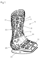
- a device for enclosing extremities is in Fig. 1 and 2 as a shell body 10 for the A patient's foot / lower leg area is shown.
- the Shell body 10 consists of two braced against each other Shell parts, namely a rear shell part 20 and a front shell part 30, both of which Shell parts 20, 30 have an approximately L-shape.
- Each Shell part 20 or 30 consists of a shaft 21 or 31 and a foot part 22 or 32, the foot parts 22, 32 of the two shell parts with their shafts 21, 31 over lateral swivel joints 25, 35 connected to each other are so that the foot parts 22, 32 to the shafts 21, 31 around Pivot axes 25a, 35a are pivotable.
- Both the two shell parts 20, 30 and their swivel joints 25, 35 suitably consist of plastic.
- the foot parts 22, 32 and the shafts 21, 31 of the two Shell bodies are designed to be open on one side, so that a receptacle in the rear shell part 20 created for the foot and lower leg is.
- the front shell body is the same 30 formed so that this with its shaft 31 and his foot 32 on the shaft 21 and the foot 22 of the rear shell part 20 can be placed.
- an outsole 23 is provided, the outer shape is adapted to the rolling motion of the foot when walking.
- the outsole 23 is designed as a cradle or provided with a walking tunnel 24.
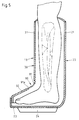
- the foot parts 22, 23 and the shafts 21, 31 of the two Shell parts 20, 30 of the shell body 10 are in the direction cup-shaped to the foot and lower leg, the formation being such that the front shell part 30 can be used in the rear shell part 20 in this way is that the side wall sections of the rear Shell part 20, the side wall sections of the Overlap shell part 30 in sections (Fig. 5).
- Both the shell part 20 and the shell part 30 have an approximately semicircular cross section, so that with stacked shell parts a section Overlap the side wall sections of the two Shell parts 20, 30 takes place.
- the shell parts have the ability to grasp the foot laterally 20, 30 have a certain elasticity, expediently the elasticity of the side walls of the two Shell parts 20, 30 from their central areas of Shaft parts to their front free edges of each Shell part increases.
- the shell parts 20 and 30 a (closer mesh) Have a lattice structure as this due to the ribs 11, 12 is effected.
- the longitudinal ribs with 11 and Cross ribs designated 12 the shaft parts 21 and 31 of the rear part 20 and the front part 30 each have a continuous longitudinal rib 11a and 12a, which are more stable than the transverse ribs 12 and the remaining longitudinal ribs.
- the transition area is wider or in diameter run larger.
- transverse ribs 12 inclined running ribs are not fixed Contours provided that the required inherent rigidity and strength or bending strength of the shell parts is achieved.
- the main idea of the invention is based on the fact that by lattice or rib-shaped design significantly saved material can be improved and also the air supply becomes.
- the shaft 21 there are two lying side by side Longitudinal ribs are provided, which form a gap 14, which is bridged via a connecting means 15.
- the gap 14 is variable in width, so that the Shaft part can be adapted to the patient's calves.
- the rear shell part 20 can also be used alone Fixation of an extremity can be used that mediates Tapes or the like are held in the shell part and is fixed.
- deformable, vacuum-tight trained and provided with at least one valve Pillow is provided, which consists of a bubble, in which a variety of relatively movable Packing is provided. That closely and suitably to that treatable limb attachable pillow is at an evacuation within a short time in the shape created during the application process hard and dimensionally stable, so that in connection with the hard shell parts a very firm, good to the respective extremity modeled sleeve arises in the area of the skin can create no pressure points because of the solidification this structure is not a radially inward direction There is pressure and there are no edges on the inside or protrusions can be formed.
- a cuff cushion can also be a cushion a suitable material can be used; also one on can put on the foot and lower leg be used.
- Movement in the patient's ankle can be prevented by adjusting the angle of inclination of the shaft part of the foot part about the pivot axis 25 or 35 is set.
- a choice of this fixed Angle can vary depending on the injury being treated within the entire adjustable swivel angle range respectively. Finding out a specific one Angles are made using appropriately trained angles Adjustment devices, with the rear shaft part 20 an angle specification for setting an angle of 90 ° or 120 ° between the foot part 22 and the Shaft 21 by means of a not shown in the drawing Angle adapter can be done.
- the front Shell part 30 To adapt the front shell part 30 to the Angular position of the foot part 22 to the shaft 21 of the rear To be able to make shell part 20 is the front Shell part 30 with an angle adjustment device 90 provided, by means of the foot part 32 to the shaft 31 in a predetermined angular position can be locked, wherein this angular position with that angular position of the Foot part 22 to the shaft 21 of the rear shell part 22 matches.
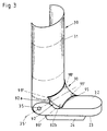
- This angle adjustment device 90 consists of a between the foot part 32 and the shaft 31 of the front shell body 30 arranged, the outer profile of the shell body 10 or the front shell part 30 accordingly shaped, plate-shaped angle adapter 95, which means Latching and locking devices 97 on the shaft 31 and the foot part 32 of the front shell part 30 releasably is held (Fig. 3 and 7).
- This angle adapter 95 engages tab-shaped front of the connection area 39 between the foot part 32 and the shaft 31 of the front Shell body 30.
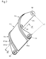
- This plate-shaped angle adapter 35 has a width due to which the foot part 32 to the shaft 31 of the Shell part 30 assumes an angular position of 90 ° (Fig. 7). This angular position is the normal position between the foot and lower leg.
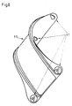
- Another Embodiment of the angle adapter 95 sees one Width due to which the foot part 32 to the shaft 31 the shell part 30 assumes an angular position of 120 °, so that if this embodiment of the angle adapter between the foot part 32 and the shaft 31 of the shell part 30 is used, the foot part to the shaft 31 the Pointing foot angle position is obtained (Fig. 8).
- the foot part 32 and the shaft 31 of the front shell part 30 points in the connection area 39 of these two parts a window-like opening 92, which extends to about in the side area of the foot part 32 and the shaft 31 extends so that the attached to the shell part 30
- Angle adapter 95 this window-like opening 92 in Form overlaps a cover tab the dimensions of the angle adapter 95 are dimensioned such that this in the window-like opening 321 can be used or with its peripheral edge on the window-like opening 92 delimiting edge attachable and here by means of Clamp or press fit is held.
- the edge reinforcements 93 on the foot part 32 and the shaft 31 of the front shell part 30 have a cross-sectional profile with a square or rectangular, Conical side surfaces 93a, 93b Surface 93c on (Fig. 10).
- the edge profiles 96 the plate-shaped angle adapter 95 are, as a corresponding the edge reinforcement 93 on the foot part 32 and the Shaft 31 cross-formed counter profile 96 '.
- the attachment and mounting of the angle adapter 95 on the Shaft 31 and the foot part 32 of the front shell part 30 7 takes place by means of two on one End 95c of the angle adapter, on the inside wall fixed locking hook 98, which in Openings 98 'in the wall surfaces of the shaft 31 and of the foot part 32 of the shell part 30 engage. With these At its end 95c, the angle adapter 95 is provided in the Openings 98 'in the wall surfaces of the shaft 31 and the foot part 32 of the shell part 30 hooked.
- the angle adapter 95 On at its other end 95d, the angle adapter 95 carries two rotatable locking hook designed as an eccentric 99, which also in corresponding openings 99 'in the wall surfaces of the shaft 31 and the foot part 32 of the Shell part 30 engage, the locking by Twisting those introduced into these openings 99 ' Locking hook 99 takes place so that it can be rotated and locking hooks 99 designed as eccentrics the angle adapter 95 over the opposite parts, here the foot part 32 and shaft 31, is tensioned, so that thereby a backlash Press fit, especially on the sloping surfaces of the bead-like edge reinforcements 93 is reached (Fig. 10).
- the number of fixed locking hooks 98 and rotatable locking hook 99 can be chosen arbitrarily his. It is essential that in each case a fixed locking hook 98 and a rotating locking hook 99 correspond with each other and into the breakthroughs 98 'in the shaft 31 and in the openings 99' in the foot part 32 engage the shell part 30.
- the plate-shaped angle adapter 95 is preferably made made of a resilient-elastic material, expediently from a plastic.
- the two shell parts 20, 30 also consist of one Plastic.
- each shell part 20 and 30 are lattice-shaped with the formation of openings between the crossing bars, which are also striped or can be formed into a band.
- This configuration has the advantage that an between the shell body wall and extremity Cuff pillow insured and non-slip is arranged as the easily deformable cushion walls in the openings of the shell body wall grille pressed so be that pillow sections beaded out of the Breakthroughs emerge or lie in them come and thus from those limiting the breakthroughs Bars are held in place.
- the adjustable to the shaft 31 Foot part 32 of the front shell part 30 over an accordion bellows running transverse to the longitudinal direction of the shaft trained portion 91 with a number of folded and film hinge-connected Material strip 91a is connected, which is the Foot part 32 and shaft 31 connecting one another, Swivel joints formed laterally on the shell body 10 35 provided with angle locking devices are.
- This section 91 has a bellows-like accordion design, the individual strips of material 91a like a film hinge are connected so that depending on the respective angular position of the foot part 32 to the shaft 31 of the shell part 30, this stretchable section 91 adjusts.
- Angle locking devices are known per se Trained way; they consist of locking devices, e.g. B. locking screws or the like. So that the predetermined Maintain angular position and only after loosening the Angle locking device can be changed.
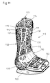
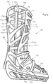
- FIGS. 11 and 12 for enclosing Fixation of extremities is in their Basic concept corresponding to that described above and formed in Fig. 1 and 2 embodiment shown.
- Matching parts have the same reference numerals denoted with a prefix "1".
- At least one gap 114 is variable in width, so that the shaft part of the patient's calf can be adjusted can.
- FIGS. 12 and 13 serve two bead-shaped, rib-shaped elevations 116 and 117 on spaced longitudinal ribs 111 as guides for the slider 115.
- the bead-shaped elevation 116 is here up to the upper edge 118 of the upper shaft part formed while the elevation 117 at a distance a ends below, which is greater than the length 11 of the slider 115.
- This makes it possible for the slide 115 in the position shown in FIG. 12 on the shell part 120 is attached, but still from the shell part 130 detached.
- Fig. 13 engages in such a way that that the grooves 151 and 152 there have a dovetail profile show that of the beaded bumps 116 and 117 is adapted in shape.
- Guide rail 117 In contrast to the embodiment shown in Fig. 12 is here Guide rail 117 'extended downwards, whereas the rail 16 has only one length Part length of the slide corresponds.
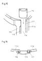
- the illustration after 15 corresponds to a perspective illustration of FIG Embodiment according to Fig. 12.
- Fig. 16 shows the over bead-like elevations 116 and 117 engaging closure for fixing the opposite longitudinal ribs 111b and 111c.
- the device for enclosing extremities 17 consists of a rear shell part 220, which has an L-shape and a shaft 221 and a foot part 222, the foot part 222 via lateral swivel joints 235 about a swivel axis 235a is pivotable so that the angle of the foot part 222 to the shaft 221 is adjustable.
- This shell part 220 suitably consists of plastic.
- the foot part 222 and the shaft 221 of the rear shell part 220 are cupped upwards and forwards open design, so that a receptacle for the foot and the lower leg is created.
- an outsole 223 is provided, the external shape to the rolling motion of the foot when walking is adjusted.
- the outsole 223 is used as a cradle trained or provided with a walking tunnel 224.
- That closely and suitably to that treatable limb attachable pillow is at an evacuation within a short time in the shape created during the application process hard and dimensionally stable, so that in connection with the hard shell part 220 a very firm, good to the respective extremity modeled sleeve arises in the area of the skin can create no pressure points because of the solidification this structure is not a radially inward direction There is pressure and there are no edges on the inside or protrusions can be formed.
- One with a cuff pillow wrapped and fixed limb is after being inserted into the shell part 220 this means not shown in the drawing Belt straps or the like held and fixed.
- a cuff cushion can also have a cushion, one on the extremity of tucked up stocking or the like in the space be provided.
- Shell part 220 with a front shell part 230 a shell body 210 are assembled also the front shell part 230 is an L-shape with a shaft 231 and a foot part 232.
- the foot part 232 can fixed to the shaft 32 of the front shell part 230 and in a predetermined angular position z. B. of 90 ° be arranged.
- Such a front shell part 230 is always be used when the extremity in the rear shell part 220 at an angular position of 90 ° of the foot to the patient's lower leg is.
- a front shell part 230 to use, in which the foot 232 to Shaft 231 arranged in different angular positions can be, in which case the foot part 232 in the predetermined Angular position can be locked.
- the front shell part 230 is also towards Foot and bowl-shaped to the lower leg, whereby then both shell parts 220, 230 are designed such that the front shell part 230 into the rear shell part 220 can be used such that the side wall sections of the shell part 220, the side wall sections of the Overlap the shell part 230 in sections.
- Both the shell part 220 and the shell part 230 have an approximately semicircular cross section, so that with nested shell parts a section by section Exceeding the side wall sections of the two Shell parts 220, 230 are carried out.
- the Shell parts 220, 230 have a certain elasticity, whereby expediently the elasticity of the side walls of the two shell parts 220,230 from their central areas the shell parts to their free edges of each Shaft part increases.
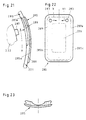
- An optional angle adjustment of the foot to the lower leg or the foot part 222 to the shaft 221 of the rear To be able to make shell part 220 is in the rear wall surface of the shaft 221 of the shell part 220, in the opposite of the foot portion 222 Wall area formed a window-like opening 280, into which a plate-shaped angle adapter 285 can be used which is provided with an engagement opening 286, in the for fixing the angle between the foot part 222 and the shaft 221 of the rear shell part 220 Cam 287 engages the foot portion 222 of the rear Shell part 220 is formed (Fig. 18, 19 and 21).
- the in this window-like opening 280 in the rear wall of the rear shell part 220 insertable angle adapter 285 have engagement openings 286 for the cams 287 in different layer arrangements for the angle adapter surface on to the foot portion 222 to the shaft 221 of the rear shell part 220 in predetermined and certain To be able to fix angular positions (Fig. 22 and 23).
- the window-like opening 280 in the wall of the rear Shell part 220 is approximately rectangular.
- the angle adapter 285 has one of the shape and the Dimensions of this window-like opening 280 corresponding Design on, for example, by means of Clamp fit held in the window-like opening 280 to become.
- the length of the engagement opening 286 in the angle adapter 285 corresponds to one in one embodiment adjustable angular range of the foot part 222 to the shaft 221 of the shell part 220.
- the cross-sectional shape of the cam 287 can be square, be rectangular or circular or some other have geometric shape.
- the engagement opening 286 faces one corresponding to the cross-sectional shape of the cam 287 Shape up.
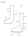
- angle adapter 285 for the most diverse angle ranges of the foot part 222 to the shaft 221 of the shell part Having 220 is available in one embodiment the engagement opening 286 '' for the cam 287 in the lower Area of the angle adapter 285 formed (Fig. 24). At this embodiment is an angular position of the foot part 222 to the shaft 221 of the shell part 220 in one Get angle of 90 °, which is the normal angle position between the foot and the lower leg.
- the angle adapter 285 also one over the The adapter length expediently slot-shaped Have engagement opening 286 '' 'for the cam 287, wherein however, in this embodiment it is then advantageous if the cam 287, for example, as a locking screw is formed (Fig. 26).
- the plate-shaped angle adapter 285 is for example by means of a clamp fit in the window-like opening 280 held in the shaft of the rear shell part 220.
- 21 to 23 is the plate-shaped angle adapter 285 on its peripheral edge 285a with a circumferential or opposite areas extending grooves 288 for engaging the window-like Opening 280 delimiting edge 280a provided.
- the plate-shaped angle adapter 285 made of a resilient elastic material, expediently made of plastic and is thereby by means of a press fit at the peripheral edge 80a of the window-like opening 280 held.
- edge section becomes the plate-shaped angle adapter 285 only in the window-like opening 280 pressed in such that the angle adapter 285 in the edge area the window-like opening 280 is held.
- the peripheral edge of the angle adapter 285 and the is bordered with window-like opening 280 Provide engagement profiles, d. H. by type of groove and spring design can be made edge profiling become.
- the plate-shaped angle adapter 285 on both of them Longitudinal edges 285b, 285c wedge-shaped upwards expanding reinforcements 289, 289a made of a resilient-elastic Material so that the press fit in the edge area the window-like opening 280 increased becomes.
- the angle adapter 285 can be replaced by means of the Drawing of pliers-like opening tools, not shown respectively.
- the plate-shaped angle adapter 285 in its upper area two at a distance from each other arranged openings 283 into which a pliers-like opening tool can be used, so that at successive directions of movement in the direction of the arrow X, X1 of the angle adapter 285 in this engagement area of the Tool is pressed together and thus the release the strip-like reinforcements 289, 289a from the edge area the window-like opening 280 takes place.
- the prerequisite is that a corresponding resilient-elastic Configuration of the angle adapter 285 is given, however, the angle adapter 285 in the area of the engagement opening 86 a high inherent rigidity for the cam 287 must have.
- each shell part 220 and 230 are lattice-shaped with the formation of Breakthroughs between the crossing bars, which can also be in the form of strips or strips, educated.
- This configuration has the advantage that one between the shell body wall and the extremity arranged cuff pillow so secured and is arranged non-slip than that easily deformable pillow walls in the openings of the shell body wall grille so that pillow sections are pressed step out of the openings in a bulge and of the bars delimiting the openings be held in place.
- the engagement openings 286, 286 ', 286 ", 286"' in the Angle adapter 85 for the cam 287 do not need as Breakthrough to be formed; also groove-shaped depressions or recesses can be in the angle adapter 285 secure the position and fix the cam 287.
- cam 287 on the Inner wall surface of the rear wall of the rear shell part Arrange 220 which is then in a suitably trained and angle adapter 285 described above intervenes.
- the one in the rear area of the foot part 222 of the shell part 220 is arranged.
- the device shown in Figs. 28, 29 and 30 for enclosing extremities is as a shell body 310 for the foot / lower leg area of a patient shown.
- the shell body 310 consists of two mutually braced shell parts, namely a rear shell part 320 and a front Shell part 330, both shell parts 320, 330 approximately have an L-shape.
- Each shell part 320 or 330 consists of a shaft 321 or 331 and a foot part 322 and 332, respectively, with the foot parts 322, 332 of the two Shell parts with their shafts 321, 331 on the side Swivel joints 325, 335 are connected to each other, so that the foot parts 322, 332 to the shafts 321, 331 about pivot axes 325a, 335a are pivotable.
- Shell parts 320, 330 as well as their swivel joints 325, 335 suitably consist of plastic.
- the foot parts 322, 332 and the shafts 321, 331 of the two Shell bodies are designed to be open on one side, so that a receptacle in the rear shell part 320 created for the foot and lower leg is.
- the front shell body is the same 330 designed so that this with its shaft 331 and its foot part 332 on the shaft 321 and the foot part 322 of the rear shell part 320 can be placed.
- an outsole 323 is provided, the outer Shape adapted to the rolling movement of the foot when walking is.
- the outsole 323 is designed as a cradle or provided with a walking tunnel 324.
- the foot parts 322, 332 and the shafts 321, 331 of the two Shell parts 320, 330 of the shell body 310 are in the direction cup-shaped to the foot and lower leg, the formation being such that the front Shell part 330 into the rear shell part 320 in such a way can be used that the side wall sections of the rear shell part 320 the side wall sections of the shell part 330 overlap in sections (Fig. 29).
- Both the shell part 320 and the shell part 330 have an approximately semicircular cross section, so that with stacked shell parts a section Overlap the side wall sections of the two Shell parts 320, 330 takes place.
- the Shell parts 320, 330 have a certain elasticity, whereby expediently the elasticity of the side walls of the two shell parts 320, 330 from their central areas the shaft parts to their front free edges every shell part increases.
- closure members in particular from strip-shaped Velcro parts are very worrying simple and quick for the one necessary before evacuation light pressure of the pillow against the closed Shell body. In this way, a sleeve can be absolutely Create correct fit and first over the Fix Velcro. After evacuation has occurred then a sleeve that solidifies in itself and in hers Form is stabilized and the extremity secured holds.
- Movement in the patient's ankle can be prevented by adjusting the angle of inclination of the shaft part of the foot part around the pivot axis 325 or 335 fixed becomes.
- a choice of this fixed angle can vary depending on the injury being treated within the entire adjustable swivel angle range respectively. Locking on a certain angle takes place by means of appropriately trained adjustment devices, with the rear shaft portion 320 a Angle specification for setting an angle of 90 ° or of 120 ° between the foot part 322 and the shaft 321 an angle adapter, not shown in the drawing can be done.
- This angle adjusting device 390 consists of a between the foot part 332 and the shaft 331 of the front Shell body 330 arranged, the outer profile of the shell body 310 or the front shell part 330 accordingly shaped, plate-shaped angle adapter 395, the by means of locking and locking devices 397 on the Shaft 331 and the foot part 332 of the front shell part 330 is detachably held (Fig. 27 and 31).
- This angle adapter 395 overlaps the front Connection area 339 between the foot part 332 and the Shaft 331 of the front shell body 330.
- This plate-shaped angle adapter 335 has a width due to which the foot part 332 to the shaft 331 of the Shell part 330 assumes an angular position of 90 ° (Fig. 31). This angular position is the normal position between the foot and lower leg.
- Another embodiment of the angle adapter 395 sees a width, due to which the foot part 332 to the Shank 331 of the shell part 330 an angular position of 120 ° so that when this embodiment of the Angle adapter between the foot part 332 and the shaft 331 of the shell part 330 is used, the foot part to the Shaft 331 the angular position is obtained (Fig. 32).
- the foot part 332 and the shaft 331 of the front shell part 330 points in connection area 339 of these two Divide a window-like opening 392, which is to about in the side area of the foot part 332 and Shaft 331 extends so that the on the shell part 330th attached angle adapter 395 this window-like opening 392 in the form of a cover flap, whereby the dimensions of the angle adapter 395 dimensioned in this way are that this in the window-like opening 332nd can be used or with its surrounding edge on the window-like opening 392 delimiting edge attachable and is held here by means of a clamp or press fit.
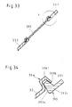
- the angle adapter 395 For holding the angle adapter 395 on the wall surfaces of the foot part 332 and the shaft 331 of the shell part 330 have the opposite, transverse to the longitudinal direction of the shaft extending edges 392a, 392b of the window-like Opening 392 on the outside beaded or different profiled strip-shaped reinforcements 393 while the angle adapter 395 at its upper edge 395a and its lower edge 395b with the reinforcements 393 to the Edges 392a, 392b correspondingly formed counter profiles are provided as edge profiles 96, so that the angle adapter 395 by means of a clamp fit on the reinforcements 393 the foot part 332 or the shaft 331 or on this the front shell part 330 is held (Fig. 33).
- the mounting and bracket of the 395 angle adapter the shaft 331 and the foot part 332 of the front shell part 30 takes place according to FIG. 31 by means of two one end 395c of the angle adapter, on the inside wall side fixed locking hooks 398, which in openings 398 'in the wall surfaces of the Shaft 331 and the foot part 332 of the shell part 330 intervention. With this its end 395c the angle adapter 395 into the provided openings 398 'in the wall surfaces of the shaft 331 and the foot part 332 of the Shell part 330 hooked.
- the 395 angle adapter carries two rotatable ones as eccentrics trained locking hook 399, also in corresponding openings 399 'in the wall surfaces of the Shaft 331 and the foot part 32 of the shell part 330 intervene, the locking by turning the in these openings 399 'inserted locking hook 399 takes place so that it can be rotated and used as an eccentric trained locking hook 399 of the angle adapter 395 over the opposite parts, here foot part 332 and shaft 331, cocked, so that a play-free press fit, in particular on the sloping surfaces of the bead-like edge reinforcements 393 is reached (Fig. 34).
- the number of fixed locking hook 398 and the rotatable Locking hook 399 can be chosen arbitrarily. Essential is that each has a fixed locking hook 398 and a rotatable locking hook 399 with each other correspond and into the openings 399 'in the Engage the foot part 332 of the shell part 330.
- the plate-shaped angle adapter 395 is preferably made made of a resilient-elastic material, expediently from a plastic.
- the two shell parts 320, 330 also consist of one Plastic.
- each shell part 320 and 330 are lattice-shaped with the formation of Breakthroughs between the crossing bars, which can also be in the form of strips or strips, educated.
- This configuration has the advantage that one between the shell body wall and the extremity arranged cuff pillow insured and is arranged non-slip than the easily deformable Pillow walls in the openings in the shell body wall grille so that pillow sections are bulge-like step out of the openings or into them come to lie and thus of the boundaries limiting the openings Bars are held in place.
- Another possibility of the angle adjustability of the Foot part 332 to the shaft 331 of the front shell part 330 29 consists in that the adjustable to the shaft 331 Foot part 332 of the front shell part 330 over an accordion bellows running transverse to the longitudinal direction of the shaft trained section 391 with a number of folded and film hinge-connected Material strip 391a is connected, which is the Foot part 332 and shaft 331 connecting each other, Swivel joints formed laterally on the shell body 310 335 provided with angle locking devices are.
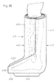
- 35 and 36 is a shell body designed for the foot / lower leg area of a patient.
- the shell body 410 consists of two braced against each other Shell parts, namely a rear shell part 420 and a front shell part 430, wherein both shell parts 420, 430 have an approximately L-shape.
- Each shell part 420 or 430 consists of a shaft 421 and 431 and a foot part 422 and 432, respectively Foot part 422 of the shell part 420 with its shaft 421 connected to one another via lateral swivel joints 35, not shown in the figures is. Both the two shell parts 420, 430 and the joints are also conveniently made of plastic.
- the foot part 422 and the shaft 421 of the rear shell part 420 are cupped upwards and forwards open design, so that a receptacle for the foot and the lower leg is created.
- an outsole 423 is provided, the external shape to the rolling motion of the foot when walking is adjusted.
- the outsole 423 is used as a cradle trained or provided with a walking tunnel 424.
- the foot part 432 and the shaft 431 of the front shell part 430 of the shell body 410 are towards the foot and bowl-shaped to the lower leg, wherein this shell part 430 is designed so that the front Shell part 430 in the rear shell part 420 such can be used that the side wall sections of the Shell part 420 the side wall sections of the shell part 430 overlap in sections.
- Both the shell part 420 and the shell part 430 have an approximately semicircular cross section, so that with nested shell parts a section by section Overlap the side wall sections of the two Shell parts 420, 430 are carried out (FIGS. 37, 38 and 39).
- the shell parts 420, 430 have a certain elasticity on, where the elasticity of the Side walls of the two shell parts 420, 430 of their central areas of the shell parts to their front free edges 420b or 430b of each shell part increases.
- That closely and suitably to that treatable limb attachable pillow is at an evacuation within a short time in the shape created during the application process hard and dimensionally stable, so that in connection with the hard shell parts a very firm, good to the respective extremity modeled sleeve arises in the area of the skin can create no pressure points because of the solidification this structure is not a radially inward direction There is pressure and there are no edges on the inside or protrusions can be formed.
- a cuff cushion can also be another Upholstery, stocking or the like for filling the interstices be used.
- closure members in particular consist of strip-shaped Velcro fasteners, take care of the before evacuation very easily and quickly necessary light pressure of the pillow the closed shell body. In this way create a sleeve of absolutely correct fit and initially fix with the Velcro fastener. After evacuation then there is a sleeve that solidifies in itself their shape is stabilized and the extremity is secured holds.
- the rear shell part 420 with a number of its upper peripheral edge 20a outgoing slit-shaped Provide openings 440, 540, which are in Extend longitudinal shaft direction of the shell part 420.
- Figs. 40 and 41 are two in the rear wall of the shell part 420 slot-shaped openings 440, 540 provided that are parallel to each other and by the least a bendable portion 445 is formed.
- the wall sections 425, 426 are fixed and have a stabilizing effect.
- each slot-shaped opening 440, 540 goes from the upper edge 420a of the rear side wall of the rear shell part 420 and initially runs with a section 443 in the longitudinal direction of the shaft 421 of the shell part 420, then this section 443 in the U-shaped Section 441 merges with its tapered leg section 442 approximately parallel to the opening section 443 is trending, as shown in FIG. 41 is.
- the slot-shaped opening 540 is corresponding the slot-shaped opening 440 is formed and is also from one in the longitudinal direction of the shaft extending portion 543 formed, to which the U-shaped Section 541 connects, the leg section 542 running parallel to the opening portion 143 is so that the two inner leg sections 442, 542 of the two openings 440, 540 each other are turned.
- the arrangement of the two slot-shaped openings 440, 540 takes place in that area of the rear Shell part 420 of the shell body 410, which is the calf of the Lower leg of the patient grasped.
- the bendable section 445 in the wall of the rear Shell part 420 is with its wall via a web 445 ' connected, the resiliently molded on the wall and is held or via an articulated connection to the wall is connected so that in the latter case section 445 has the function of a seesaw and the calf and the Adapts calf muscle movements.
- a joint connection relieves pressure on the Wade, since section 445 is practically free-swinging, yes is always in contact with the calf.
- the articulation which can also be designed as a film hinge, is the section 445 together with its web 445 'around the Swivel axis 445a movable (Fig. 41).
- the resilient and individually formed sections 425, 426, 445 of the shell part 420 adjacent to the upper circumferential Edge 420 a has a number of slot-shaped openings 450 for receiving a strip-shaped closure device 460, which is designed as a webbing or from strip-shaped Velcro parts can exist to in the Adjustment position of the rear shell part 420 in the area to determine its shaft 421.
- a strip-shaped closure device 460 which is designed as a webbing or from strip-shaped Velcro parts
- the locking members only engage on the fixed wall sections 425, 425 on.
- the closure members can also be on one end of these be attached. This type of attachment of the closure members is preferable in all cases, however, because the free Mobility of sections 445 by means of its web 445 'is not impaired, with a longitudinal displaceability the bridge to the outside is possible.
- the fixing device designed in this way is thus included an integrated calf adjustment without this the dimensional stability of the shell body 410 is impaired becomes.
- the rear shell part 420 is an adjustment elasticity on the patient's lower leg and calf given.
- front shell part 430 becomes a movement prevented in the rear shell part 420.
- the normal angle position between foot and lower leg is 90 ° therefore always observable.
- the lower leg is stationary Treatment of the patient after surgery in the rear shell part 420 and is fixed in it, so that the correct anatomical position is maintained can be.
- the fixation of the foot and the Lower leg in the normal angle position of 90 ° achieved a high level of stabilization.
- the back wall and / or the side walls of the shaft part 420 are also different be formed and incisions running like that slot-shaped openings described above 440, 540. Because the shell part 420 made of plastic there is a possibility, instead of slot-like openings 440, 540 in the longitudinal direction of the shell part running sections in the form of material dilutions to provide the accordion-like moving the individual wall sections against each other deform.
Landscapes
- Health & Medical Sciences (AREA)
- Animal Behavior & Ethology (AREA)
- Public Health (AREA)
- Engineering & Computer Science (AREA)
- Biomedical Technology (AREA)
- Heart & Thoracic Surgery (AREA)
- Vascular Medicine (AREA)
- Life Sciences & Earth Sciences (AREA)
- Nursing (AREA)
- Orthopedic Medicine & Surgery (AREA)
- Veterinary Medicine (AREA)
- General Health & Medical Sciences (AREA)
- Orthopedics, Nursing, And Contraception (AREA)
- Apparatus For Radiation Diagnosis (AREA)
- Absorbent Articles And Supports Therefor (AREA)
- Materials For Medical Uses (AREA)
- Electrotherapy Devices (AREA)
- Facsimile Transmission Control (AREA)
Description
- Fig. 1 und 2
- jeweils verschiedene Ausführungsformen der erfindungsgemäßen Vorrichtung in perspektivischer Ansicht,
- Fig. 3
- eine schematische, schaubildliche Ansicht des vorderen Schalenteiles der aus zwei L-förmigen Schalenteilen bestehenden Fixierungsvorrichtung mit eingesetztem Winkeladapter,
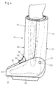
- Fig. 4
- eine Seitenansicht der Fixierungsvorrichtung aus einem Schalenkörper mit zwei L-förmigen Schalenteilen,
- Fig. 5
- die Fixierungsvorrichtung gemäß Fig. 4 teils in einer Seitenansicht, teils in einem senkrechten Längsschnitt,
- Fig. 6
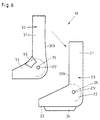
- in einer Seitenansicht die beiden L-förmigen Schalenteile des Schalenkörpers vor deren Verspannung,
- Fig. 7
- in einer schaubildlichen Ansicht einen Winkeladapter für eine Winkelstellung von 90° zwischen dem Fußteil und dem Schaft des vorderen Schalenkörpers,
- Fig. 8
- in einer schaubildlichen Ansicht einen Winkeladapter für eine Winkelstellung von 120° zwischen dem Fußteil und dem Schaft des vorderen Schalnkörpers,
- Fig. 9
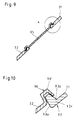
- einen Schnitt gemäß Linie IX-IX in Fig. 7,
- Fig. 10
- in einer vergrößerten Wiedergabe den Verbindungsabschnitt A zwischen dem Winkeladapter und der Wandfläche des Schaftes des vorderen Schalenkörpers,
- Fig. 11 und 12
- jeweils verschiedene Ausführungsformen der Vorrichtung in perspektivischer Ansicht,
- Fig. 13
- eine vergrößerte Teilansicht der Schaftoberteilausbildung mit einer durch einen Schieber gegebenen Verstellmöglichkeit,
- Fig. 14
- einen Schnitt entlang der Linie XIV-XIV nach Fig. 13,
- Fig. 15
- eine weitere Ausführungsform eines Schiebers,
- Fig. 16
- eine Draufsicht auf die Ausbildung nach Fig. 15,
- Fig. 17
- eine Ansicht des rückseitigen Schalenteiles der aus zwei L-förmigen Schalenteilen bestehenden Fixierungsvorrichtung,
- Fig. 18
- eine Seitenansicht der Fixierungsvorrichtung aus einem Schalenkörper mit zwei L-förmigen Schalenteilen,
- Fig. 19
- die Fixierungsvorrichtung teils in einer Seitenansicht, teils in einem senkrechten Längsschnitt,
- Fig. 20
- in einer Seitenansicht die beiden L-förmigen Schalenteile des Schalenkörpers vor deren Verspannung,
- Fig. 21
- in einer Seitenansicht die aus einem plattenförmigen Winkeladapter und einem in diesen eingreifenden Nocken bestehende Winkeleinstelleinrichtung,
- Fig. 22
- in einer Vorderansicht den plattenförmigen Winkeladapter,
- Fig. 23
- eine Ansicht von oben auf den Winkeladapter gemäß Fig. 22,
- Fig. 24
- eine schematische Ansicht eines Winkeladapters zur Einstellung eines der Normalwinkelstellung von 90° entsprechenden Winkels,
- Fig. 25
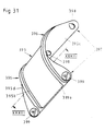
- eine schematische Ansicht eines Winkeladapters zur Einstellung eines der Spitzfußstellung von 120° entsprechenden Winkels,
- Fig. 26
- eine schematische Ansicht eines Winkeladapters mit einer Winkeleinstellmöglichkeit über einen größeren Bereich,
- Fig. 27
- eine schaubildliche Ansicht des vorderen Schalenteiles der aus zwei L-förmigen Schalenteilen bestehenden Fixierungsvorrichtung mit eingesetztem Winkeladapter,
- Fig. 28
- eine Seitenansicht der Fixierungsvorrichtung aus einem Schalenkörper mit zwei L-förmigen Schalenteilen,
- Fig. 29
- die Fixierungsvorrichtung gemäß Fig. 28 teils in einer Seitenansicht, teils in einem senkrechten Längsschnitt,
- Fig. 30
- in einer Seitenansicht die beiden L-förmigen Schalenteile des Schalenkörpers vor deren Verspannung,
- Fig. 31
- in einer schaubildlichen Ansicht einen Winkeladapter für eine Winkelstellung von 90° zwischen dem Fußteil und dem Schaft des vorderen Schalenkörpers,
- Fig. 32
- in einer schaubildlichen Ansicht einen Winkeladapter für eine Winkelstellung von 120° zwischen dem Fußteil und dem Schaft des vorderen Schalenkörpers,
- Fig. 33
- einen Schnitt gemäß Linie XXXIII-XXXIII in Fig. 31,
- Fig. 34
- in einer vergrößerten Wiedergabe den Verbindungsabschnitt A zwischen dem Winkeladapter und der Wandfläche des Schaftes des vorderen Schalenkörpers,
- Fig. 35
- eine Seitenansicht der Fixierungsvorrichtung aus einem Schalenkörper mit zwei L-förmigen Schalenteilen,
- Fig. 36
- die Fixierungsvorrichtung teils in einer Seitenansicht, teils in einem senkrechten Längsschnitt,
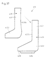
- Fig. 37
- in einer Seitenansicht die beiden L-förmigen Schalenteile des Schalenkörpers vor deren Verspannung,
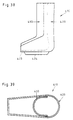
- Fig. 38
- eine Seitenansicht der Schalenkörper,
- Fig. 39
- einen waagerechten Schnitt gemäß Linie XXXIX-XXXIX in Fig. 36,
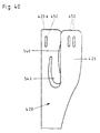
- Fig. 40
- eine Seitenansicht des rückwärtigen Schalenteiles und
- Fig. 41
- eine Rückansicht des rückwärtigen Schalenteiles.
Claims (49)
- Vorrichtung zur umschließenden Fixierung von Extremitäten und Extremitätenbereichen im Bereich von Unterschenkel und Oberschenkel, bestehend aus einem Schalenkörper (10) aus zwei gegeneinander verspannbaren L-förmigen Schalenteilen (20,30) mit einem etwa halbkreisförmigen Querschnittsprofil, die die zu umschließende Extremität umgeben, wobei zwischen den Schalenteilen (20,30) und der Extremität mindestens ein evakuierbares Manschettenkissen vorgesehen ist, in dessen zwischen den beiden Kissenwänden gelegenen Innenraum eine Vielzahl von relativ zueinander beweglichen Füllkörpern vorgesehen ist,dadurch gekennzeichnet, daß die beiden Schalenteile (20,30) eine sich über die gesamte Wandfläche eines jeden Schalenteils erstreckende Gitterstruktur aufweisen, die aus Gitterstreben und/oder Gitterrippen in Längs- (11) und Querrippen (12) besteht,wobei zumindest eine Längsrippe (11a) pro Schalenteil vorgesehen ist, die sich im wesentlichen über die gesamte Länge des Schalenteils erstreckt und die mindestens so breit oder mit einem größeren Querschnitt ausgestaltet ist wie die übrigen Längsstreben, Querstreben oder -rippen (11,12) und die Anschlußstellen (13) der Querrippen (12) an der sich über die gesamte Länge erstreckenden Längsrippe (11a) breiter als der sich anschließende, vorzugsweise in der Breite oder im Durchmesser verjüngend ausgebildete Querrippenteil sind,daß zumindest der rückseitige Schaftoberteil (21) des Schalenkörpers (10) einen Längsschlitz (14) zur Breiten- oder Durchmesserverstellung aufweist, wobei die den Längsschlitz (14) begrenzenden Längsrippen über ein lösbares Verbindungselement (15;115) auf den gewünschten Abstand einstellbar und fixierbar sind, und daß das vordere Schalenteil (30) ein zu dessen Schaft (31) über ein Gelenk (35) verschwenkbares Fußteil (32) und das rückseitige Schalenteil (20) ein zu seinem Schaft (21) über ein zweites Gelenk (25) verschwenkbares Fußteil (22) aufweist, wobei das Gelenk (35) und/oder das zweite Gelenk (25) vermittels einer Winkeleinstelleinrichtung (90) in jeder Winkelstellung arretierbar ist/sind.
- Vorrichtung nach Anspruch 1, dadurch gekennzeichnet, daß die Gitterstreben und/oder Gitterrippen (11,12) eine Breite oder einen Durchmesser zwischen 1,5 cm und 3 cm haben.
- Vorrichtung nach einem der Ansprüche 1 und 2, dadurch gekennzeichnet, daß die Gitterstreben und/oder Gitterrippen (11,12) jeweils in Abhängigkeit von den auf sie wirkenden Belastungen unterschiedlich breit und/oder mit einem unterschiedlichen Durchmesser versehen sind.
- Vorrichtung nach einem der Ansprüche 1 bis 3, dadurch gekennzeichnet, daß das zum Schaft (31) verstellbare Fußteil (32) des vorderen Schalenteiles (30) über einen quer zur Schaftlängsrichtung verlaufenden ziehharmonikabalgartig ausgebildeten Abschnitt (91) mit einer Anzahl von gefalteten, filmscharnierartig miteinander verbundenen Materialstreifen (91a) verbunden ist, wobei die das Fußteil (32) und den Schaft (31) miteinander verbindenden, seitlich an dem Schalenkörper (10) ausgebildeten Schwenkgelenke (35) mit Winkelarretierungseinrichtungen versehen sind.
- Vorrichtung nach einem der Ansprüche 1 bis 3, dadurch gekennzeichnet, daß die Winkeleinstelleinrichtung (90) aus einem zwischen dem Fußteil (32) und dem Schaft (31) des vorderen Schalenteils (30) angeordneten, dem Außenprofil des Schalenkörpers (10) bzw. des vorderen Schalenteils (30) entsprechend geformten rippen-, gitter- oder plattenförmigen Winkeladapter (95) besteht, der mittels Rast- und Verriegelungseinrichtungen (97) an dem Schaft (31) und dem Fußteil (32) des vorderen Schalenteils (30) lösbar gehalten ist.
- Vorrichtung nach Anspruch 5, dadurch gekennzeichnet, daß der rippen-, gitter- oder plattenförmige Winkeladapter (95) eine Breite aufweist, aufgrund der das Fußteil (32) zu dem Schaft (31) des vorderen Schalenteils (30) eine Winkelstellung von 90° einnimmt.
- Vorrichtung nach Anspruch 5, dadurch gekennzeichnet, daß der rippen-, gitter- oder plattenförmige Winkeladapter (95) eine Breite aufweist, aufgrund der das Fußteil (32) zu dem Schaft (31) des vorderen Schalenteils (30) eine Winkelstellung von 120° einnimmt.
- Vorrichtung nach einem der Ansprüche 1 bis 7, dadurch gekennzeichnet, daß das Fußteil (32) und der Schaft (31) des vorderen Schalenteils (30) im Verbindungsbereich (39) eine fensterartige Durchbrechung (92) aufweist, die sich bis in den Seitenbereich des Fußteiles (32) und des Schaftes (31) erstreckt und in der der rippen-, gitter- oder plattenförmige Winkeladapter (95) angeordnet ist.
- Vorrichtung nach Anspruch 8, dadurch gekennzeichnet, daß die gegenüberliegenden, quer zur Schaftlängsrichtung verlaufenden Ränder (92a,92b) der fensterartigen Durchbrechung (92) außenseitig wulstartige oder andersartig profilierte, leistenförmige Verstärkungen (93) aufweisen und daß der rippen-, gitter- oder plattenförmige Winkeladapter (95) an seinem oberen (95a) und unteren Rand (95b) mit den Verstärkungen (93) entsprechend ausgebildeten Gegenprofilen als Randprofile (96) versehen und mittels Klemmsitz an den Verstärkungen (93) an dem Fußteil (32) oder dem Schaft (31) des vorderen Schalenteils (30) gehalten ist.
- Vorrichtung nach Anspruch 9, dadurch gekennzeichnet, daß die Randverstärkungen (93) an dem Fußteil (32) und dem Schaft (31) des vorderen Schalenteils (30) ein Querschnittsprofil mit einer quadratischen oder rechteckförmigen, konisch nach oben verlaufende Seitenflächen (93a,93b) aufweisende Fläche (93c) aufweisen, und daß die Randprofile (96) an dem rippen-, gitter- oder plattenförmigen Winkeladapter (95) als entsprechendes, die Randverstärkungen (93) an dem Fußteil (32) und dem Schaft (31) übergreifendes Gegenprofil (96') ausgebildet sind.
- Vorrichtung nach einem der Ansprüche 5 bis 10, dadurch gekennzeichnet, daß zur Befestigung des rippen-, gitter- oder plattenförmigen Winkeladapters (95) an dem Schaft (31) und dem Fußteil (32) des vorderen Schalenteils (30) der Winkeladapter (95) einendseitig (95c) und innenwandseitig mindestens zwei feststehende Verriegelungshaken (98), die in Durchbrechungen (98') in den Wandflächen des Schaftes (31) und des Fußteils (32) eingreifen, und an seinem anderen Ende (95d) mindestens zwei drehbare, als Exzenter ausgebildete Verriegelungshaken (99) aufweist, die in entsprechende Durchbrechungen (99') in den Wandflächen des Schaftes (31) und des Fußteiles (32) des vorderen Schalenteils (30) eingreifen.
- Vorrichtung nach einem der Ansprüche 5 bis 11, dadurch gekennzeichnet, daß der rippen-, gitter- oder plattenförmige Winkeladapter (95) aus einem federnd-elastischen Material, zweckmäßigerweise aus einem Kunststoff besteht.
- Vorrichtung nach einem der Ansprüche 1 bis 12, dadurch gekennzeichnet, daß die beiden Schalenteile (20,30) und/oder die Winkeleinstelleinrichtung (90) aus einem Kunststoff bestehen.
- Vorrichtung nach einem der Ansprüche 1 bis 13, dadurch gekennzeichnet, daß an den Schalenteileninnenseiten ein Manschettenkissen oder Polster angeordnet ist, in dem eine Vielzahl von relativ zueinander beweglichen Füllkörpern enthalten ist.
- Vorrichtung nach einem der Ansprüche 1 bis 14, dadurch gekennzeichnet, daß den Längsschlitz (14) umrahmende Führungen (16',17') über ein lösbares Verbindungselement (15;115) auf den gewünschten Abstand einstellbar und fixierbar sind, wobei das Verbindungselement ein Schieber (15;115) mit die Führungen teilweise im Umfang umgreifenden oder in die Führung eingreifenden Randprofilierungen ist.
- Vorrichtung nach Anspruch 15, dadurch gekennzeichnet, daß eine der beiden Führungen (16',17') die andere in Richtung der Schalenoberteillängsachse um eine Länge (a) überragt, die mindestens so groß ist wie die Länge (1) des Schiebers oder des Verbindungselementes, wobei eine der beiden Führungen (16') im wesentlichen bis zum Schalenoberteilrand (18) ausgebildet ist.
- Vorrichtung nach Anspruch 15, dadurch gekennzeichnet, daß das lösbare Verbindungselement oder der Schieber (15;115) mittels eines Anschlages begrenzt in Richtung des Schaftoberteilrandes (18;118) verschiebbar ist.
- Vorrichtung nach einem der Ansprüche 1 bis 17, dadurch gekennzeichnet, daß das Schaftoberteil (10) zwei im wesentlichen parallel laufende Rippen oder wulstförmige Erhebungen (16,17) aufweist, die in entsprechend geformte Nuten des Schiebers eingreifen, der längsverschiebbar, aber gegen ein seitliches Herausnehmen gesichert ist.
- Vorrichtung nach Anspruch 18, dadurch gekennzeichnet, daß die führungen (16',17') eine Schwalbenschwanzführung ist.
- Vorrichtung nach einem der Ansprüche 1 bis 19, dadurch gekennzeichnet, daß das Verbindungselement oder der Schieber (15;115) über zwei Längsrippen des Schaftoberteils greift und entlang diesem führbar ist.
- Vorrichtung nach einem der Ansprüche 1 bis 20, dadurch gekennzeichnet, daß die beabstandeten, einen Zwischenraum bildenden Längsrippen mit wulstartigen, Führungsschienen (16',17') bildenden Erhebungen (16,17) versehen sind.
- Vorrichtung nach einem der Ansprüche 1 bis 21, dadurch gekennzeichnet, daß von den beiden, eine etwa L-Form aufweisenden Schalenteilen (220;230) mit einem etwa halbkreisförmigen Querschnittsprofil und mit einem Schaft (221;231) und einem Fußteil (222;232) das rückwärtige Schalenteil (220) ein zu dessen Schaft (221) winkelverstellbares Fußteil (222) und in dem dem Fußteil (222) gegenüberliegenden Wandbereich eine fensterartige Durchbrechung (280) mit einem in diese eingesetzten, austauschbaren plattenförmigen Winkeladapter (285) aufweist, der mit einer Eingriffvertiefung oder Eingrifföffnung (286) versehen ist, in die zur Winkelfestlegung zwischen dem Fußteil (222) und dem Schaft (221) des rückwärtigen Schalenteiles (220) ein Nocken (287) eingreift, der zur Fixierung einer vorbestimmten Winkelstellung in dem rückwärtigen Bereich des Fußteiles (222) an diesem angeformt ist.
- Vorrichtung nach Anspruch 22, dadurch gekennzeichnet, daß in die fensterartige Durchbrechung (280) im rückwärtigen Schalenteil (220) Winkeladapter (285) mit unterschiedlichen Lagenanordnungen der Eingrifföffnungen (286,286',286",286"') für den Nocken (287) zur Winkeladapterfläche zur Fixierbarkeit des Fußteiles (222) zum Schaft (221) einsetzbar sind.
- Vorrichtung nach einem der Ansprüche 22 und 23, dadurch gekennzeichnet, daß die fensterartige Durchbrechung (280) in der Wand des rückwärtigen Schalenteiles (220) etwa rechteckförmig ist und der Winkeladpater (285) eine der Form und den Abmessungen der fensterartigen Durchbrechung (280) entsprechende Ausgestaltung aufweist.
- Vorrichtung nach Anspruch 23, dadurch gekennzeichnet, daß die Eingriffsöffnung (286") für den Nocken (287) im unteren Bereich des Winkeladapters (285) ausgebildet ist.
- Vorrichtung nach Anspruch 23, dadurch gekennzeichnet, daß die Eingriffsöffnung (286') für den Nocken (287) im oberen Bereich des Winkeladapters (285) ausgebildet ist.
- Vorrichtung nach einem der Ansprüche 22 bis 26, dadurch gekennzeichnet, daß der Winkeladapter (285) eine sich über die Adapterlänge erstreckende schlitzförmige Eingriffsöffnung (286"') für den Nocken (287) aufweist.
- Vorrichtung nach einem der Ansprüche 22 bis 27, dadurch gekennzeichnet, daß der plattenförmige Winkeladapter (285) an seinem umlaufenden Rand (285a) mit einer umlaufenden oder sich über sich gegenüberliegende Bereiche erstreckende Nuten (288) zum Eingriff des die fensterartige Durchbrechung (280) begrenzenden Randes (280a) versehen ist.
- Vorrichtung nach einem der Ansprüche 22 bis 28, dadurch gekennzeichnet, daß der plattenförmige Winkeladapter (285) aus einem federnd-elastischen Material, zweckmäßigerweise einem Kunststoff, besteht und mittels Klemmsitz am umlaufenden Rand (280a) der fensterartigen Durchbrechung (280) gehalten ist.
- Vorrichtung nach einem der Ansprüche 22 bis 29, dadurch gekennzeichnet, daß der plattenförmige Winkeladapter (285) an seinen beiden Längsseitenkanten (285b,285c) keilförmig sich nach oben erweiternde Verstärkungen (289,289a) aus einem federnd-elastischen Material aufweist.
- Vorrichtung nach einem der Ansprüche 22 bis 30, dadurch gekennzeichnet, daß der plattenförmige Winkeladapter (285) in seinem oberen Bereich zwei im Abstand voneinander angeordnete Durchbrechungen (283) zum Eingriff eines zangenartigen Öffnungswerkzeuges aufweist.
- Vorrichtung nach einem der Ansprüche 22 bis 31, dadurch gekennzeichnet, daß der Nocken (287) als Feststellschraube ausgebildet ist.
- Vorrichtung nach einem der vorangegangenen Ansprüche 1 bis 32, dadurch gekennzeichnet, daß von den beiden eine etwa L-Form aufweisenden Schalenteilen (320, 330) mit einem etwa halbkreisförmigen Querschnittsprofil und mit einem Schaft (321,331) und einem Fußteil (322,332) das vordere Schalenteil (330) ein zu dessen Schaft (331) winkelverstellbares Fußteil (332) und dem Schaft (331) eine Winkeleinstelleinrichtung (390) aufweist, vermittels der das Fußteil (332) zum Schaft (331) in einer vorgegebenen Winkelstellung arretierbar ist, wobei das rückwärtige Schalenteil (320) ein zu dessen Schaft (321) winkelverstellbares Fußteil (322) oder ein zu dessen Schaft (321) in einem vorgegebenen Winkel festgestelltes Fußteil (322) aufweist.
- Vorrichtung nach Anspruch 33, dadurch gekennzeichnet, daß das zum Schaft (331) verstellbare Fußteil (332) des vorderen Schalenteiles (330) über einen quer zur Schaftlängsrichtung verlaufenden ziehharmonikabalgartig ausgebildeten Abschnitt (391) mit einer Anzahl von gefalteten, filmscharnierartig miteinander verbundenen Materialstreifen (391a) verbunden ist, wobei die das Fußteil (332) und den Schaft (331) miteinander verbindenden seitlich an dem Schalenkörper (10) ausgebildeten Schwenkgelenke (335) mit Winkelarretierungseinrichtungen versehen sind.
- Vorrichtung nach Anspruch 33, dadurch gekennzeichnet, daß die Winkeleinstelleinrichtung (390) aus einem zwischen dem Fußteil (332) und dem Schaft (331) des vorderen Schalenteils (330) angeordneten, dem Außenprofil des Schalenkörpers (310) bzw. des vorderen Schalenteils (330) entsprechend geformten plattenförmigen Winkeladapter (395) besteht, der mittels Rast- und Verriegelungseinrichtungen (397) an dem Schaft (331) und dem Fußteil (332) des vorderen Schalenteils (330) lösbar gehalten ist.
- Vorrichtung nach einem der Ansprüche 33 bis 35, dadurch gekennzeichnet, daß der plattenförmige Winkeladapter (395) eine Breite aufweist, aufgrund der das Fußteil (332) zu dem Schaft (331) des vorderen Schalenteils (330) eine Winkelstellung von 90° einnimmt.
- Vorrichtung nach einem der Ansprüche 33 bis 36, dadurch gekennzeichnet, daß der plattenförmige Winkeladapter (395) eine Breite aufweist, aufgrund der das Fußteil (332) zu dem Schaft (331) des vorderen Schalenteils (330) eine Winkelstellung von 120° einnimmt.
- Vorrichtung nach einem der Ansprüche 33 bis 37, dadurch gekennzeichnet, daß das Fußteil (332) und der Schaft (331) des vorderen Schalenteils (330) im Verbindungsbereich (339) eine fensterartige Durchbrechung (392) aufweist, die sich bis in den Seitenbereich des Fußteiles (332) und des Schaftes (331) erstreckt und in der der plattenförmige Winkeladapter (395) angeordnet ist.
- Vorrichtung nach einem der Ansprüche 33 bis 38, dadurch gekennzeichnet, daß die gegenüberliegenden, quer zur Schaftlängsrichtung verlaufenden Ränder (392a,392b) der fensterartigen Durchbrechung (392) außenseitig wulstartige oder andersartig profilierte leistenförmige Verstärkungen (393) aufweisen und daß der plattenförmige Winkeladapter (395) an seinem oberen (395a) und unteren Rand (395b) mit den Verstärkungen (393) entsprechend ausgebildeten Gegenprofilen als Randprofile (396) versehen und mittels Klemmsitz an den Verstärkungen (393) an dem Fußteil (332) oder dem Schaft (331) des vorderen Schalenteils (330) gehalten ist.
- Vorrichtung nach Anspruch 39, dadurch gekennzeichnet, daß die Randverstärkungen (393) an dem Fußteil (332) und dem Schaft (331) des vorderen Schalenteils (330) ein Querschnittsprofil mit einer quadratischen oder rechteckförmigen, konisch nach oben verlaufende Seitenflächen (393a,393b) aufweisenden Fläche (393c) aufweisen, und daß die Randprofile (396) an dem plattenförmigen Winkeladapter (395) als entsprechendes, die Randverstärkungen (393) an dem Fußteil (332) und dem Schaft (331) übergreifendes Gegenprofil (396') ausgebildet sind.
- Vorrichtung nach einem der Ansprüche 33 bis 40, dadurch gekennzeichnet, daß zur Befestigung des plattenförmigen Winkeladapters (395) an dem Schaft (331) und dem Fußteil (332) des vorderen Schalenteils (330) der Winkeladapter (395) einendseitig (395c) und innenwandseitig mindestens zwei feststehende Verriegelungshaken (398), die in Durchbrechungen (398') in den Wandflächen des Schaftes (331) und des Fußteils (332) eingreifen, und an seinem anderen Ende (395d) mindestens zwei drehbare, als Exzenter ausgebildete Verriegelungshaken (399) aufweist, die in entsprechende Durchbrechungen (399') in den Wandflächen des Schaftes (331) und des Fußteiles (332) des vorderen Schalenteils (330) eingreifen.
- Vorrichtung nach einem der Ansprüche 33 bis 41, dadurch gekennzeichnet, daß der plattenförmige Winkeladapter (395) aus einem federnd-elastischen Material, zweckmäßigerweise aus einem Kunststoff, besteht.
- Vorrichtung nach einem der Ansprüche 1 bis 42, dadurch gekennzeichnet, daß von den beiden, eine etwa L-Form aufweisenden Schalenteilen (420,430) mit einem etwa halbkreisförmigen Querschnittsprofil das rückwärtige Schalenteil (420) unter Ausbildung mindestens eines abbiegbaren Abschnittes (445) vom oberen Schalenteilrand (420a) ausgehend schlitzförmige Durchbrechungen (440,540) aufweist, die sich über einen Bereich in Schalenteillängsrichtung derart erstrecken, daß in dem rückwärtigen Schalenteil (420) federnd-elastische und gegeneinander verschiebbare Wandabschnitte (425,426,445) ausgebildet sind, und daß eine diese Abschnitte (425,426, 445) fixierende Einrichtung (460) vorgesehen ist.
- Vorrichtung nach Anspruch 43, dadurch gekennzeichnet, daß in dem rückwärtigen Schalenteil (420) zwei im Abstand, in Schalenteillängsrichtung verlaufende und sich vom oberen Schalenrand (420a) erstreckende schlitzförmige Durchbrechungen (440,540) ausgebildet sind, die in etwa U-förmige Abschnitte (441, 541) mit parallel zueinander verlaufenden schlitzförmigen Schenkelabschnitten (442,542) auslaufen, so daß in der Wand des rückwärtigen Schalenteiles (420) zwei zungenförmige Wandabschnitte (46,146) ausgebildet sind, wobei die zu den schlitzförmigen Durchbrechungen (40,140) benachbarten Wandabschnitte (25,26) feststehend sind.
- Vorrichtung nach einem der Ansprüche 43 und 44, dadurch gekennzeichnet, daß der zwischen den schlitzförmigen Schenkelabschnitten (442,542) ausgebildetde Steg (445') federnd-elastisch an der Wand des rückwärtigen Schalenteils (420) gehalten ist.
- Vorrichtung nach einem der Ansprüche 43 und 44, dadurch gekennzeichnet, daß der zwischen den schlitzförmigen Schenkelabschnitten (442,542) ausgebildete Steg (445') über eine Gelenkverbindung mit der Wand des rückwärtigen Schalenteiles (420) verbunden ist.
- Vorrichtung nach einem der Ansprüche 43 bis 46, dadurch gekennzeichnet, daß zur Fixierung der gegeneinander verschiebbaren Wandabschnitte (425,426, 445,446,546) in Anpassung an die jeweilige Wadenform und -größe des Unterschenkels das rückwärtige Schalenteil (420) benachbart zu seinem oberen Rand (420a) eine Anzahl von schlitzförmigen Durchbrechungen (450) zur Aufnahme eines Verschlußorgans, bevorzugterweise eines Spanngurtes oder -bandes (460), vorgesehen ist.
- Vorrichtung nach einem der Ansprüche 43 bis 46, dadurch gekennzeichnet, daß zur Fixierung der Wandabschnitte (425,426) des rückwärtigen Schalenteils (420) in diesen benachbart zum oberen Schalenteilrand (420a) schlitzförmige Durchbrechungen (450) zur Aufnahme von Verschlußorganen, bevorzugterweise von Spanngurten oder -bändern (460) vorgesehen sind.
- Vorrichtung nach Anspruch 48, dadurch gekennzeichnet, daß die Verschlußorgane an den Wandabschnitten (425,426) des rückwärtigen Schalenteils (420) befestigt sind.
Applications Claiming Priority (11)
| Application Number | Priority Date | Filing Date | Title |
|---|---|---|---|
| DE9307548U | 1993-05-21 | ||
| DE9307549U DE9307549U1 (de) | 1993-05-21 | 1993-05-21 | Vorrichtung zur umschließenden Fixierung von Extremitäten und Extremitätenbereichen |
| DE9307549U | 1993-05-21 | ||
| DE9307550U DE9307550U1 (de) | 1993-05-21 | 1993-05-21 | Vorrichtung zur umschließenden Fixierung von Extremitäten und Extremitätenbereichen |
| DE9307548U DE9307548U1 (de) | 1993-05-21 | 1993-05-21 | Vorrichtung zur umschließenden Fixierung von Extremitäten und Extremitätenbereichen |
| DE9307550U | 1993-05-21 | ||
| DE9317421U | 1993-11-13 | ||
| DE9317421U DE9317421U1 (de) | 1993-05-21 | 1993-11-13 | Vorrichtung zur umschließenden Fixierung von Extremitäten und Extremitätenbereichen |
| DE9404210U | 1994-03-12 | ||
| DE19949404210 DE9404210U1 (de) | 1994-03-12 | 1994-03-12 | Vorrichtung zur umschließenden Fixierung von Extremitäten und Extremitätenbereichen |
| PCT/EP1994/001648 WO1994027529A1 (de) | 1993-05-21 | 1994-05-20 | Vorrichtung zur umschliessenden fixierung von extremitäten und extremitätenbereichen |
Publications (2)
| Publication Number | Publication Date |
|---|---|
| EP0774939A1 EP0774939A1 (de) | 1997-05-28 |
| EP0774939B1 true EP0774939B1 (de) | 2001-08-22 |
Family
ID=27511877
Family Applications (1)
| Application Number | Title | Priority Date | Filing Date |
|---|---|---|---|
| EP94918353A Expired - Lifetime EP0774939B1 (de) | 1993-05-21 | 1994-05-20 | Vorrichtung zur umschliessenden fixierung von extremitäten und extremitätenbereichen |
Country Status (5)
| Country | Link |
|---|---|
| EP (1) | EP0774939B1 (de) |
| AT (1) | ATE204450T1 (de) |
| AU (1) | AU6970894A (de) |
| DE (1) | DE59409840D1 (de) |
| WO (1) | WO1994027529A1 (de) |
Cited By (1)
| Publication number | Priority date | Publication date | Assignee | Title |
|---|---|---|---|---|
| WO2022162208A1 (de) * | 2021-02-01 | 2022-08-04 | Ferd. Hauber Gmbh | Orthese |
Families Citing this family (6)
| Publication number | Priority date | Publication date | Assignee | Title |
|---|---|---|---|---|
| US5833639A (en) * | 1995-10-27 | 1998-11-10 | Johnson & Johnson Professional, Inc. | Short leg walker |
| US5713837A (en) * | 1995-12-28 | 1998-02-03 | Royce Medical Company | Unitary orthopaedic brace |
| DE19722118A1 (de) * | 1997-05-27 | 1999-02-04 | Hauber Ferd Gmbh | Sprunggelenkorthese |
| DE10163706B4 (de) * | 2001-12-21 | 2006-09-21 | Oped Ag | Schalenanordnung zur fixierenden Aufnahme eines Unterschenkels |
| USD519211S1 (en) | 2003-12-18 | 2006-04-18 | Dj Orthopedics, Llc | Walker |
| US12357488B2 (en) | 2020-10-14 | 2025-07-15 | Darco International, Inc. | Rear entry walker |
Family Cites Families (9)
| Publication number | Priority date | Publication date | Assignee | Title |
|---|---|---|---|---|
| US3955565A (en) * | 1973-12-05 | 1976-05-11 | Johnson Jr Glenn W | Orthopedic apparatus |
| US4029090A (en) * | 1976-07-26 | 1977-06-14 | Dawson Jr Garrett W | Horse foreleg brace |
| DE3228753C2 (de) * | 1982-07-31 | 1994-01-13 | Helmut John | Fußlagerungsschiene mit im Bereich des Spannes Schlitze aufweisender Schale |
| US4727865A (en) * | 1985-03-07 | 1988-03-01 | Hill Byrne Christopher R | Replaceable rigid cast with integral fasteners |
| US4803975A (en) * | 1987-03-31 | 1989-02-14 | Meyers Andrew H | Orthotic device for controlling knee instabilities |
| EP0355930A3 (de) * | 1988-08-05 | 1990-11-07 | Peter Dr. Habermeyer | Vorrichtung zur umschliessenden Fixierung von Extremitäten |
| DE4029120A1 (de) * | 1990-09-13 | 1992-03-19 | Habermeyer Peter | Vorrichtung zur umschliessenden fixierung von extremitaeten |
| US5176623A (en) * | 1991-10-15 | 1993-01-05 | Professional Care Products Incorporated | Multiple fixed angle orthopaedic appliance |
| DE4217061A1 (de) * | 1992-05-22 | 1993-11-25 | Habermeyer Peter | Vorrichtung zur umschließenden Fixierung von Extremitäten und Extremitätenbereichen |
-
1994
- 1994-05-20 EP EP94918353A patent/EP0774939B1/de not_active Expired - Lifetime
- 1994-05-20 AT AT94918353T patent/ATE204450T1/de not_active IP Right Cessation
- 1994-05-20 AU AU69708/94A patent/AU6970894A/en not_active Abandoned
- 1994-05-20 DE DE59409840T patent/DE59409840D1/de not_active Expired - Lifetime
- 1994-05-20 WO PCT/EP1994/001648 patent/WO1994027529A1/de not_active Ceased
Cited By (2)
| Publication number | Priority date | Publication date | Assignee | Title |
|---|---|---|---|---|
| WO2022162208A1 (de) * | 2021-02-01 | 2022-08-04 | Ferd. Hauber Gmbh | Orthese |
| US12622799B2 (en) | 2021-02-01 | 2026-05-12 | Ferd. Hauber Gmbh | Orthosis |
Also Published As
| Publication number | Publication date |
|---|---|
| WO1994027529A1 (de) | 1994-12-08 |
| DE59409840D1 (de) | 2001-09-27 |
| EP0774939A1 (de) | 1997-05-28 |
| AU6970894A (en) | 1994-12-20 |
| ATE204450T1 (de) | 2001-09-15 |
Similar Documents
| Publication | Publication Date | Title |
|---|---|---|
| EP0641184B1 (de) | Vorrichtung zur umschliessenden fixierung von körperextremitäten | |
| EP0505527B1 (de) | Vorrichtung zur umschliessenden fixierung von extremitäten | |
| EP0677282B1 (de) | Knieschiene | |
| WO2007003168A1 (de) | Rumpforthese | |
| EP0164374A1 (de) | Orthese für kniegelenke. | |
| EP2858608B1 (de) | Spannvorrichtung für orthesen | |
| EP0981310B1 (de) | Fraktur-roll-orthese | |
| EP3378448B1 (de) | Modulare knieorthese | |
| DE60205192T2 (de) | Gelenkschiene zur Steuerung und Regelung der Beugung des Kniegelenks | |
| WO1994027529A1 (de) | Vorrichtung zur umschliessenden fixierung von extremitäten und extremitätenbereichen | |
| EP2988707B1 (de) | Entlastungsorthese | |
| DE102017108839A1 (de) | Rückenorthese | |
| EP3090709A2 (de) | Orthese zur therapeutischen behandlung | |
| DE69332170T2 (de) | Gerät zur behandlung von thoraxdeformierungen wie skoliose | |
| EP4146127B1 (de) | Orthese | |
| DE9317421U1 (de) | Vorrichtung zur umschließenden Fixierung von Extremitäten und Extremitätenbereichen | |
| DE4418855A1 (de) | Knieorthese | |
| DE9307550U1 (de) | Vorrichtung zur umschließenden Fixierung von Extremitäten und Extremitätenbereichen | |
| DE9307548U1 (de) | Vorrichtung zur umschließenden Fixierung von Extremitäten und Extremitätenbereichen | |
| EP4212134B1 (de) | Fussgelenk-orthese | |
| DE9407551U1 (de) | Vorrichtung zur umschließenden Fixierung von Extremitäten und Extremitätenbereichen | |
| EP4633550A1 (de) | Reversibel schliessbare extremitätenorthese oder -bandage oder sporthilfsmittel | |
| DE9404210U1 (de) | Vorrichtung zur umschließenden Fixierung von Extremitäten und Extremitätenbereichen | |
| DE102016105353B4 (de) | Orthese | |
| DE19745334C2 (de) | Umschnallbarer Kompressenfixierer für die Katheteraustrittsstelle bei Peritonealdialyseverfahren |
Legal Events
| Date | Code | Title | Description |
|---|---|---|---|
| PUAI | Public reference made under article 153(3) epc to a published international application that has entered the european phase |
Free format text: ORIGINAL CODE: 0009012 |
|
| 17P | Request for examination filed |
Effective date: 19951011 |
|
| AK | Designated contracting states |
Kind code of ref document: A1 Designated state(s): AT CH DE ES FR GB IT LI |
|
| GRAG | Despatch of communication of intention to grant |
Free format text: ORIGINAL CODE: EPIDOS AGRA |
|
| GRAG | Despatch of communication of intention to grant |
Free format text: ORIGINAL CODE: EPIDOS AGRA |
|
| GRAH | Despatch of communication of intention to grant a patent |
Free format text: ORIGINAL CODE: EPIDOS IGRA |
|
| 17Q | First examination report despatched |
Effective date: 20010216 |
|
| GRAH | Despatch of communication of intention to grant a patent |
Free format text: ORIGINAL CODE: EPIDOS IGRA |
|
| GRAA | (expected) grant |
Free format text: ORIGINAL CODE: 0009210 |
|
| AK | Designated contracting states |
Kind code of ref document: B1 Designated state(s): AT CH DE ES FR GB IT LI |
|
| PG25 | Lapsed in a contracting state [announced via postgrant information from national office to epo] |
Ref country code: IT Free format text: LAPSE BECAUSE OF FAILURE TO SUBMIT A TRANSLATION OF THE DESCRIPTION OR TO PAY THE FEE WITHIN THE PRE;WARNING: LAPSES OF ITALIAN PATENTS WITH EFFECTIVE DATE BEFORE 2007 MAY HAVE OCCURRED AT ANY TIME BEFORE 2007. THE CORRECT EFFECTIVE DATE MAY BE DIFFERENT FROM THE ONE RECORDED.SCRIBED TIME-LIMIT Effective date: 20010822 |
|
| REF | Corresponds to: |
Ref document number: 204450 Country of ref document: AT Date of ref document: 20010915 Kind code of ref document: T |
|
| REG | Reference to a national code |
Ref country code: CH Ref legal event code: EP |
|
| GBT | Gb: translation of ep patent filed (gb section 77(6)(a)/1977) |
Effective date: 20010822 |
|
| REF | Corresponds to: |
Ref document number: 59409840 Country of ref document: DE Date of ref document: 20010927 |
|
| ET | Fr: translation filed | ||
| REG | Reference to a national code |
Ref country code: GB Ref legal event code: IF02 |
|
| PG25 | Lapsed in a contracting state [announced via postgrant information from national office to epo] |
Ref country code: ES Free format text: LAPSE BECAUSE OF FAILURE TO SUBMIT A TRANSLATION OF THE DESCRIPTION OR TO PAY THE FEE WITHIN THE PRESCRIBED TIME-LIMIT Effective date: 20020228 |
|
| PG25 | Lapsed in a contracting state [announced via postgrant information from national office to epo] |
Ref country code: AT Free format text: LAPSE BECAUSE OF NON-PAYMENT OF DUE FEES Effective date: 20020520 |
|
| PG25 | Lapsed in a contracting state [announced via postgrant information from national office to epo] |
Ref country code: LI Free format text: LAPSE BECAUSE OF NON-PAYMENT OF DUE FEES Effective date: 20020531 Ref country code: CH Free format text: LAPSE BECAUSE OF NON-PAYMENT OF DUE FEES Effective date: 20020531 |
|
| PLBE | No opposition filed within time limit |
Free format text: ORIGINAL CODE: 0009261 |
|
| STAA | Information on the status of an ep patent application or granted ep patent |
Free format text: STATUS: NO OPPOSITION FILED WITHIN TIME LIMIT |
|
| 26N | No opposition filed | ||
| REG | Reference to a national code |
Ref country code: CH Ref legal event code: PL |
|
| PGFP | Annual fee paid to national office [announced via postgrant information from national office to epo] |
Ref country code: FR Payment date: 20120608 Year of fee payment: 19 Ref country code: GB Payment date: 20120522 Year of fee payment: 19 |
|
| PGFP | Annual fee paid to national office [announced via postgrant information from national office to epo] |
Ref country code: DE Payment date: 20130722 Year of fee payment: 20 |
|
| GBPC | Gb: european patent ceased through non-payment of renewal fee |
Effective date: 20130520 |
|
| REG | Reference to a national code |
Ref country code: FR Ref legal event code: ST Effective date: 20140131 |
|
| PG25 | Lapsed in a contracting state [announced via postgrant information from national office to epo] |
Ref country code: GB Free format text: LAPSE BECAUSE OF NON-PAYMENT OF DUE FEES Effective date: 20130520 |
|
| REG | Reference to a national code |
Ref country code: DE Ref legal event code: R071 Ref document number: 59409840 Country of ref document: DE |
|
| PG25 | Lapsed in a contracting state [announced via postgrant information from national office to epo] |
Ref country code: FR Free format text: LAPSE BECAUSE OF NON-PAYMENT OF DUE FEES Effective date: 20130531 |
|
| PG25 | Lapsed in a contracting state [announced via postgrant information from national office to epo] |
Ref country code: DE Free format text: LAPSE BECAUSE OF EXPIRATION OF PROTECTION Effective date: 20140521 |