EP0775498A2 - Verfahren und Vorrichtung für die Entnahme und Entsorgung von Körperflüssigkeiten - Google Patents
Verfahren und Vorrichtung für die Entnahme und Entsorgung von Körperflüssigkeiten Download PDFInfo
- Publication number
- EP0775498A2 EP0775498A2 EP96300375A EP96300375A EP0775498A2 EP 0775498 A2 EP0775498 A2 EP 0775498A2 EP 96300375 A EP96300375 A EP 96300375A EP 96300375 A EP96300375 A EP 96300375A EP 0775498 A2 EP0775498 A2 EP 0775498A2
- Authority
- EP
- European Patent Office
- Prior art keywords
- wall portion
- set forth
- container
- wall
- chamber
- Prior art date
- Legal status (The legal status is an assumption and is not a legal conclusion. Google has not performed a legal analysis and makes no representation as to the accuracy of the status listed.)
- Withdrawn
Links
Images


Classifications
-
- A—HUMAN NECESSITIES
- A61—MEDICAL OR VETERINARY SCIENCE; HYGIENE
- A61M—DEVICES FOR INTRODUCING MEDIA INTO, OR ONTO, THE BODY; DEVICES FOR TRANSDUCING BODY MEDIA OR FOR TAKING MEDIA FROM THE BODY; DEVICES FOR PRODUCING OR ENDING SLEEP OR STUPOR
- A61M1/00—Suction or pumping devices for medical purposes; Devices for carrying-off, for treatment of, or for carrying-over, body-liquids; Drainage systems
- A61M1/60—Containers for suction drainage, adapted to be used with an external suction source
Definitions
- the invention relates to medical methods and apparatus for removing body fluids from patients and disposing of the body fluids.
- the invention also relates to suction canisters used in the collection of fluids from patients.
- Suction canisters are used in hospital environments and particularly during various surgical procedures to store drained bodily fluid from a patient.
- suction canisters are used in conjunction with a vacuum source which enables bodily fluid to be drained from the patient and stored in the canister.
- Each canister generally includes a receptacle for holding the bodily fluid, a lid with a vacuum port and a patient port, a suction conduit connecting the vacuum port to a vacuum source, and a patient conduit for conveying the bodily fluid from the patient into the receptacle through the patient port.
- a negative pressure gradient is created in the interior of the receptacle so that the bodily fluid is drawn from the patient and into the suction canister via the patient conduit.
- Bodily fluid can be poured from the suction canister down the hospital sink and into the sewer system, can be incinerated as a liquid or solid, or can be disposed of at an approved hazardous waste site. If hospital employees have to handle the bodily fluid, spattering of the bodily fluid can result in hospital employees contacting the hazardous fluid.
- the invention provides improved methods and apparatus for removing body fluids from patients and disposing of the body fluids.
- the invention provides a suction canister including a container having a chamber for collecting fluids, a patient port, and a vacuum port.
- the patient and vacuum ports communicate with the chamber.
- the chamber is partially defined by a wall, preferably the bottom wall, including a protrusion extending into the chamber.
- the protrusion defines a passageway having an open outer end and a closed inner end.
- the protrusion includes a thin portion such that the protrusion can be broken to provide communication between the passageway and the chamber for draining fluid contained in the suction canister.
- the passageway has an axis
- the wall is molded with mold parts movable relative to each other in a direction parallel to the axis
- the thin portion has a reduced thickness in a direction parallel to the axis. This makes it easier to control the thickness of the thin portion during molding, because it is easier to control the relative positions of the mold parts in the direction of parting than in other directions.
- the invention preferably also provides a drainage device for breaking the thin portion of the protrusion and draining the canister.
- the invention also provides a method of removing body fluids from a patient and disposing of the body fluids.
- the method includes the steps of providing a molded suction canister including a molded-in drain, providing a drainage device for automatically opening the molded-in drain and draining the contents of the suction canister, collecting body fluids in the suction canister, connecting the suction canister to the drainage device, and operating the drainage device so that the drainage device opens the drain and drains the contents of the suction canister.
- the invention also provides another method of removing body fluids from a patient and disposing of the body fluids, the method comprising the steps of providing a container including a bottom wall having therein a drain, providing a drainage device for automatically opening the drain and draining the contents of the container, collecting body fluids in the container, placing the container on the drainage device, and operating the drainage device so that the drainage device opens the drain and drains the contents of the container.
- the drain can either be integrally molded with the container or provided by a plug closing an opening in the container.
- the invention provides a suction canister or container that is easily drained of potentially hazardous fluid without contact with the fluid.
- the suction canister when used in conjunction with the drainage device allows a convenient means of disposing of the fluid content.
- the apparatus comprises a suction canister 10.
- the suction canister includes a container 14 which defines a chamber 18 for collecting drained fluid.
- the container 14 is preferably plastic (such as clear polystyrene) and is injection molded.
- the container 18 has an open upper end 22 and a closed lower end 26.
- the container 18 is defined by an annular side wall 30 and by a bottom wall 34.
- the bottom wall 34 includes a molded-in drain formed by a protrusion 38 extending into the chamber 18.
- molded-in it is meant that the container 14 and the drain are formed in a single injection molding process.
- the protrusion 38 defines a passageway 42 that tapers upwardly and has an open lower or outer end 46 and a blind or closed upper or inner end 50. More particularly, the protrusion 38 includes a first wall portion 54.
- the first wall portion 54 defines the outer end 46 of the passageway 42.
- the first wall portion 54 is not uniform in height throughout its entire circumference due to a curvature of the bottom wall 34. However, it should be noted that the first wall portion 54 can be uniform in height throughout its circumference. Further, the height of the first wall portion 54 is preferably minimized to minimize the volume of fluid that remains in the suction canister 10 after it has been drained.
- the protrusion 38 also includes a second wall portion 58 that defines the closed inner end 50 of the passageway 42.
- the second wall portion 58 defines an outwardly or downwardly opening, non-circular socket 62 at the inner end 50 of the passageway 42 as best shown in Figs. 2 and 4.
- the socket is preferably hexagonal.
- a thin or frangible wall portion 66 integrally connects the first wall portion 54 and the second wall portion 58.
- the frangible wall portion 66 can be broken to provide communication between the passageway 42 and the chamber 18 to enable draining of the fluid from the suction canister 10.
- the frangible wall portion 66 is small in size (preferably about .010 inch thick) to provide for ease of breakage when draining is desired yet is also strong enough to withstand the tensile and circumferential stresses when a vacuum is created in the chamber 18 when the suction canister 10 is being filled with fluid. Further, due to the placement and configuration of the frangible wall portion 66 and the socket 62, inadvertent breaking of the protrusion 38 is minimized.
- the suction canister 10 also includes a lid 70 which closes the upper end 22 of the container 14.
- the lid 70 has therein a patient port 74 which communicates with the chamber 18. Extending upwardly from the patient port is a patient port wall 78.
- a patient conduit 82 is affixed to the patient port wall 78 by forcing one end 86 of the patient conduit 82 over the patient port wall 78.
- the other end 90 of the patient conduit 82 communicates with the fluid to be drained such as in a patient cavity 94.
- a cap (not shown) can be placed over the patient port wall 78 to prevent any fluid from leaking from the suction canister 10.
- the lid 70 of the suction canister 10 also includes a vacuum port 98 which communicates with the chamber 18 via a filter (not shown).
- the filter can be, for example, a hydrophobic filter. Extending upwardly from the vacuum port 98 is a vacuum port wall 102.
- the vacuum port 98 communicates with a vacuum source 106 via a suction conduit 110.
- the suction conduit 110 is affixed to the vacuum port wall 102 by forcing one end 114 of the suction conduit 110 over the vacuum port wall 102.
- the other end 118 of the suction conduit 110 is placed in communication with the vacuum source 106.
- the filter prevents contamination of the vacuum source 106.
- a cap (not shown) can be placed over the vacuum port wall 102 to prevent any fluid from leaking from the suction canister 10.
- the suction canister 10 is used in the collection of fluids as follows.
- One end 114 of the suction conduit 110 is affixed to the vacuum port wall 102 as previously described and the other end 118 is placed in communication with the vacuum source 106.
- One end 86 of the patient conduit 82 is affixed to the patient port wall 78 as previously described and the other end 90 is placed in communication with the fluid to be drained such as in the patient cavity 94.
- a vacuum is created in the chamber 18 of the container 14 such that fluid is drawn from the patient cavity 94, through the patient conduit 82 and into the container 14 via the patient port 74.
- the patient conduit 82 and the suction conduit 110 can be detached from the lid 70 of the suction canister 10.
- the caps can then be placed on the patient port wall 78 and the vacuum port wall 114 as previously described to prevent fluid from leaking from the container 14.
- the suction canister 10 can then be stored until the suction canister is to be drained of its fluid contents.
- the apparatus 5 also comprises a drainage device 122 with an upwardly tapered drain conduit 126 and a movable tool 130 as shown in Fig. 1.
- the drainage device 122 uses water pressure and a venturi to create a vacuum that suctions the fluid from the container 14 and delivers this fluid directly to the sanitary sewer line.
- the drainage device 122 can include a device such as the Deknatel EDUCTORTM manufactured by Deknatel, Inc. of Fall River, Massachusetts.
- a suitable drainage device is also disclosed in U.S. Patent No. 5,217,038, which is incorporated herein by reference.
- the drainage device 122 breaks the protrusion 38 as follows.
- the suction canister 10 is placed onto the drainage device 122 so that the drain conduit 126 of the drainage device 122 is inserted into the passageway 42 of the suction canister 10 as shown in Fig. 3.
- the drain conduit 126 has a configuration that is complementary to the passageway 42.
- a friction fit between the drain conduit 126 and the first wall portion 54 of the suction canister 10 provides a fluid seal.
- the tool 130 is extended upwardly from the drainage device 122 and into the socket 62 of the passageway 42 as shown in Fig. 3.
- the tool 130 has a configuration that is complementary to that of the socket 62. Referring now to Fig. 5, further upward movement of the tool 130 (as depicted by arrow A) in conjunction with rotational movement of the tool 130 (as depicted by arrow B) breaks the frangible wall portion 66 of the protrusion 38, thereby disconnecting the second wall portion 58 from the first wall portion 54. The breakage of the protrusion 38 allows the fluid within the container 14 to exit the chamber 18 and enter the drainage device 122 via the drain conduit 126. As shown by the small arrows in Fig. 5, the fluid flows through the conduit 126 around the tool 130. The seal between the drain conduit 126 and the first wall portion 54 of the protrusion 38 prevents fluid from flowing anywhere but through the passageway 42 and into the drainage device 122.
- the caps on the patient port wall 78 and/or the vacuum port wall 102 can be removed to vent the chamber 18 to aid in drainage of the fluid.
- a vent could be provided in the drainage device 122 to aid in drainage of the fluid from the suction canister 10.
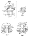
- FIG. 6 An apparatus 200 which is a first alternative embodiment of the invention is illustrated in Figs. 6 and 7. Except as described below, the apparatus 200 is identical to the apparatus 5, and common elements have been given the same reference numerals.
- the apparatus 200 comprises a suction canister 210 including a container 214.
- the container 214 is preferably made of clear polystyrene.
- the passageway 42 has an axis 226, and the container 214 is preferably injection molded using mold parts 218 and 222 which are movable relative to each other or part in the direction of the axis 226.
- the mold parts 218 and 222 part vertically as shown in Fig. 6. This is identical to the manner in which the container 14 shown in Figs. 1-5 is preferably molded.
- the container 214 has a thin wall portion 266 with a reduced thickness in the direction of parting of the mold parts 218 and 222, i.e., in the vertical direction in Fig. 6.
- the thin wall portion 266 has a reduced thickness in a direction parallel to the axis 226.
- the thickness of the wall portion 266 is preferably .010 inch, and can be relatively easily controlled.
- the wall portion 266 also has a radial or horizontal dimension that is substantially greater than the reduced thickness. This radial dimension is preferably approximately .060 inch. Variation of this dimension during molding is not critical.
- the thin wall portion 266 is easily broken when draining is desired yet is also strong enough to withstand the stress of a vacuum in the chamber 18. In fact, it has been found that the thin wall portion 266 can be broken simply by pushing upwardly on the second wall portion 58. It is not necessary to twist the wall portion 58 in order to break the wall portion 266.
- the container 214 also differs from the container 14 in that the socket 62 is star-shaped rather than hexagonal. Obviously, any non-circular shape can be employed.
- bottom wall of the container could be conical or sloped toward the drain for improved drainage.
- FIG. 8 An apparatus 300 which is a second alternative embodiment of the invention is illustrated in Figs. 8 and 9. Except as described below, the apparatus 300 is identical to the apparatus 5, and common elements have been given the same reference numerals.
- the apparatus 300 comprises a container 305 with a bottom wall 309 having therein an opening 313 closed by a plug 317 inserted in the opening 313.
- the plug 317 is preferably made of an elastomer or thermoplastic and snaps into the opening.
- the plug has therein a blind central passageway 321 with a closed upper end 325.
- the drainage device 122 includes a pointed conduit or hollow needle 329 that pierces the upper end 325 of the passageway 321 so that fluid flows out of the container 305 through the needle or conduit 329.
- FIG. 10 An apparatus 400 which is a third alternative embodiment of the invention is illustrated in Figs. 10 and 11. Except as described below, the apparatus 400 is identical to the apparatus 5, and common elements have been given the same reference numerals.
- the apparatus 400 comprises a container 405 with a bottom wall 409 having therein an opening 413 closed by a plug 417 inserted in the opening 413.
- the plug 417 is preferably made of an elastomer or thermoplastic and snaps into the opening.
- the drainage device 122 includes a conduit 429 with a closed upper end and side openings 433. The conduit 429 pushes the plug up into the container 405 so that fluid flows out of the container 405 through the openings 433 and into the conduit 429.
- FIG. 12 An apparatus 500 which is a fourth alternative embodiment of the invention is illustrated in Figs. 12 and 13. Except as described below, the apparatus 500 is identical to the apparatus 5, and common elements have been given the same reference numerals.
- the apparatus 500 comprises a container 505 with a bottom wall 509 having therein an opening 513 closed by a plug 517 inserted in the opening 513.
- the plug 517 is preferably made of a thermoplastic and snaps into the opening.
- the plug has therein a blind central passageway 521 with a closed lower end 525.
- the drainage device 122 includes a pointed conduit or hollow needle 529 that pierces the lower end 525 of the passageway 521 so that fluid flows out of the container 505 through the needle or conduit 529.
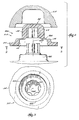
- FIG. 14-16 An apparatus 600 which is a fifth alternative embodiment of the invention is illustrated in Figs. 14-16. Except as described below, the apparatus 600 is identical to the apparatus 5, and common elements have been given the same reference numerals.
- the apparatus 600 comprises a container 605 with a bottom wall 609 having therein an internally threaded opening 613 closed by a plug 617.
- the plug 617 is preferably made of a thermoplastic and threads into the opening 613.
- the plug has a hexagonal head 621.
- the drainage device 122 includes a tool 629 with a socket 633 that engages the plug head 621 and unthreads the plug 617 from the opening 613 so that fluid flows out of the container 605 through the opening 613.
- FIG. 17 and 18 An apparatus 700 which is a sixth alternative embodiment of the invention is illustrated in Figs. 17 and 18. Except as described below, the apparatus 700 is identical to the apparatus 5, and common elements have been given the same reference numerals.
- the apparatus 700 comprises a container 705 with a bottom wall 709 having therein an opening 713 closed by a plug 717.
- the plug 717 is preferably made of a thermoplastic and is glued, ultrasonically welded or otherwise secured over the opening.
- the plug 717 has a construction similar to the bottom wall of the container 214 shown in Figs. 6 and 7.
- the plug 717 has a first wall portion 54, a second wall portion 58 and a frangible wall portion 266 like those of the suction canister 210.
- the drainage device 122 includes a conduit 729 with a closed upper end and side openings 733.
- the conduit 729 breaks the thin wall portion 721 and extends into the container 705 so that fluid flows out of the container 705 through the openings 733 and into the conduit 729.
- drain arrangements and drain opening devices have been disclosed, it should be understood that other types of drains and other devices for opening drains are within the scope of the invention.
- container includes suction canisters, urine collectors, chest drainage devices and other types of containers for collecting body fluids.
Landscapes
- Health & Medical Sciences (AREA)
- Heart & Thoracic Surgery (AREA)
- Vascular Medicine (AREA)
- Engineering & Computer Science (AREA)
- Anesthesiology (AREA)
- Biomedical Technology (AREA)
- Hematology (AREA)
- Life Sciences & Earth Sciences (AREA)
- Animal Behavior & Ethology (AREA)
- General Health & Medical Sciences (AREA)
- Public Health (AREA)
- Veterinary Medicine (AREA)
- External Artificial Organs (AREA)
Applications Claiming Priority (4)
| Application Number | Priority Date | Filing Date | Title |
|---|---|---|---|
| US08/547,759 US5683371A (en) | 1994-12-29 | 1995-10-24 | Suction canister apparatus and method |
| US547759 | 1995-10-24 | ||
| US582358 | 1996-01-05 | ||
| US08/582,358 US5688255A (en) | 1994-12-29 | 1996-01-05 | Method and apparatus for removing and disposing of body fluids |
Publications (2)
| Publication Number | Publication Date |
|---|---|
| EP0775498A2 true EP0775498A2 (de) | 1997-05-28 |
| EP0775498A3 EP0775498A3 (de) | 1997-09-10 |
Family
ID=27068645
Family Applications (1)
| Application Number | Title | Priority Date | Filing Date |
|---|---|---|---|
| EP96300375A Withdrawn EP0775498A3 (de) | 1995-10-24 | 1996-01-19 | Verfahren und Vorrichtung für die Entnahme und Entsorgung von Körperflüssigkeiten |
Country Status (3)
| Country | Link |
|---|---|
| US (2) | US5688255A (de) |
| EP (1) | EP0775498A3 (de) |
| MX (1) | MX9600975A (de) |
Cited By (3)
| Publication number | Priority date | Publication date | Assignee | Title |
|---|---|---|---|---|
| EP0882440A3 (de) * | 1997-06-03 | 1999-03-24 | B. Braun Melsungen Ag | Absaugvorrichtung für Körperflüssigkeiten |
| US6316036B1 (en) | 1997-12-10 | 2001-11-13 | Pechiney Emballage Flexible Europe | Tear tape for plastic packaging |
| CN110049752A (zh) * | 2016-10-26 | 2019-07-23 | 康尔福盛2200有限公司 | 用于移动监测引流导管的设备和方法 |
Families Citing this family (48)
| Publication number | Priority date | Publication date | Assignee | Title |
|---|---|---|---|---|
| US5807359A (en) | 1993-06-08 | 1998-09-15 | Bemis Manufacturing Company | Medical suction system |
| US6358232B1 (en) | 1994-12-29 | 2002-03-19 | Bemis Manufacturing Company | Method and apparatus for removing and disposing of body fluids |
| US5688255A (en) * | 1994-12-29 | 1997-11-18 | Bemis Manufacturing Company | Method and apparatus for removing and disposing of body fluids |
| US6244311B1 (en) | 1994-12-29 | 2001-06-12 | Bemis Manufacturing Company | Method and apparatus for removing and disposing of body fluids |
| US5975096A (en) * | 1996-08-16 | 1999-11-02 | Dornoch Medical Systems, Inc. | Liquid waste disposal and canister flushing system and method |
| US6783023B1 (en) | 1997-12-12 | 2004-08-31 | Jian-Hua Fan | Legged pot |
| US6056874A (en) * | 1998-04-25 | 2000-05-02 | Goodman; Lowell R. | Piercing filter oil containment boot |
| US6131334A (en) * | 1998-07-20 | 2000-10-17 | Fan; Jianhua | Self-watering tray |
| DE60042315D1 (de) | 1999-03-09 | 2009-07-16 | Covidien Ag | Medizinische drainagevorrichtung mit durchflusswiderstand |
| USD436887S1 (en) | 1999-04-13 | 2001-01-30 | Jianhua Fan | Pot with an adjustable mouthpiece |
| USD435906S1 (en) | 1999-08-06 | 2001-01-02 | Becton Dickinson And Company | Integrated port closed collection container |
| US6409971B1 (en) * | 1999-08-06 | 2002-06-25 | Becton, Dickinson And Company | Device and method for collecting and transferring a urine specimen |
| US6263887B1 (en) | 2000-01-14 | 2001-07-24 | Dornoch Medical Systems, Inc. | Liquid waste disposal and canister flushing system and method |
| US6588436B2 (en) * | 2000-01-14 | 2003-07-08 | Dornoch Medical Systems, Inc. | Liquid waste disposal with canister flushing system having removable lid and method therefor |
| US7674248B2 (en) | 2000-03-28 | 2010-03-09 | Bemis Manufacturing Company | Medical suction apparatus and methods for draining same |
| WO2001072350A1 (en) | 2000-03-28 | 2001-10-04 | Bemis Manufacturing Company | Medical suction apparatus and methods for draining same |
| US7585292B2 (en) | 2000-03-28 | 2009-09-08 | Bemis Manufacturing Company | Medical suction apparatus and draining of same |
| EP1343549A2 (de) | 2000-12-19 | 2003-09-17 | Hill-Rom Services, Inc. | Absaugeinrichtung mit niedrigem entsorgungsrisiko |
| WO2002055134A2 (en) | 2001-01-12 | 2002-07-18 | Bemis Mfg Co | Method and apparatus for disposing of bodily fluids from a container |
| US6733481B2 (en) | 2001-06-15 | 2004-05-11 | Melody Ow | Containment system for biohazardous fluids |
| US20050101922A1 (en) * | 2003-11-07 | 2005-05-12 | Bemis Manufacturing Company | Suction canister and drainage of same |
| US7615037B2 (en) | 2005-12-14 | 2009-11-10 | Stryker Corporation | Removable inlet manifold for a medical/surgical waste collection system, the manifold including a driver for actuating a valve integral with the waste collection system |
| US8025173B2 (en) | 2006-09-07 | 2011-09-27 | Allegiance Corporation | Collapsible canister liner for medical fluid collection |
| US9889239B2 (en) | 2007-03-23 | 2018-02-13 | Allegiance Corporation | Fluid collection and disposal system and related methods |
| JP2010522060A (ja) | 2007-03-23 | 2010-07-01 | アレジアンス、コーポレイション | 交換可能な収集および他の機能を有する流体収集および廃棄システムならびに関連する方法 |
| US20090230009A1 (en) * | 2008-03-14 | 2009-09-17 | Ogburn Sean T | Corner protector |
| WO2011008961A1 (en) | 2009-07-15 | 2011-01-20 | Allegiance Corporation | Fluid collection and disposal system and related methods |
| US20110139667A1 (en) * | 2009-12-11 | 2011-06-16 | Burgess James E | Stackable Suction Canister and Lid Assembly |
| USD679807S1 (en) * | 2010-04-29 | 2013-04-09 | Medline Industries, Inc. | Fluid collection container lid |
| USD694404S1 (en) | 2011-06-09 | 2013-11-26 | Medline Industries, Inc. | Fluid collection container lid |
| US8920394B2 (en) | 2012-12-19 | 2014-12-30 | Dornoch Medical Systems, Inc. | Suction canister liner and system |
| USD731049S1 (en) * | 2013-03-05 | 2015-06-02 | Covidien Lp | EVQ housing of an exhalation module |
| USD693001S1 (en) | 2013-03-08 | 2013-11-05 | Covidien Lp | Neonate expiratory filter assembly of an exhalation module |
| USD692556S1 (en) | 2013-03-08 | 2013-10-29 | Covidien Lp | Expiratory filter body of an exhalation module |
| USD731048S1 (en) | 2013-03-08 | 2015-06-02 | Covidien Lp | EVQ diaphragm of an exhalation module |
| USD736905S1 (en) | 2013-03-08 | 2015-08-18 | Covidien Lp | Exhalation module EVQ housing |
| USD744095S1 (en) | 2013-03-08 | 2015-11-24 | Covidien Lp | Exhalation module EVQ internal flow sensor |
| USD731065S1 (en) | 2013-03-08 | 2015-06-02 | Covidien Lp | EVQ pressure sensor filter of an exhalation module |
| USD701601S1 (en) * | 2013-03-08 | 2014-03-25 | Covidien Lp | Condensate vial of an exhalation module |
| US9474837B2 (en) | 2013-07-03 | 2016-10-25 | Dornoch Medical Systems, Inc. | Fluid level sensor cover for a medical waste fluid collection and disposal system |
| US12350418B2 (en) | 2019-04-12 | 2025-07-08 | Stryker Corporation | Manifold for a medical waste collection system |
| US10471188B1 (en) | 2019-04-12 | 2019-11-12 | Stryker Corporation | Manifold for filtering medical waste being drawn under vacuum into a medical waste collection system |
| US11318242B2 (en) | 2019-04-12 | 2022-05-03 | Stryker Corporation | Manifold for a medical waste collection system |
| USD919799S1 (en) | 2019-11-11 | 2021-05-18 | Stryker Corporation | Manifold housing for a medical waste collection device |
| USD930850S1 (en) | 2019-11-20 | 2021-09-14 | Stryker Corporation | Specimen collection tray |
| USD956967S1 (en) | 2019-11-11 | 2022-07-05 | Stryker Corporation | Manifold housing for a medical waste collection device |
| USD996640S1 (en) | 2019-11-11 | 2023-08-22 | Stryker Corporation | Specimen collection tray |
| USD1031076S1 (en) | 2019-11-20 | 2024-06-11 | Stryker Corporation | Specimen collection tray |
Family Cites Families (38)
| Publication number | Priority date | Publication date | Assignee | Title |
|---|---|---|---|---|
| US3363627A (en) * | 1966-10-20 | 1968-01-16 | Deknatel Inc | Underwater drainage apparatus |
| US3699964A (en) * | 1970-07-02 | 1972-10-24 | Bard Inc C R | Closed urinary drainage and irrigation system |
| US3768478A (en) * | 1972-08-25 | 1973-10-30 | Vermitron Medical Prod Inc | Aspiration device for body fluids |
| US4015603A (en) * | 1975-10-10 | 1977-04-05 | Deknatel Inc. | Surgical drainage system with pressure indicator |
| US3989046A (en) * | 1975-01-30 | 1976-11-02 | Sorenson Research Co., Inc. | Asceptic disposble rigid receiver for body drainage |
| US4112948A (en) * | 1976-05-07 | 1978-09-12 | Deknatel, Inc. | Surgical drainage system with pressure indicator and enclosed source of liquid |
| US4275732A (en) * | 1977-08-19 | 1981-06-30 | Gereg Gordon A | Suction canister with membrane shut-off valve |
| US4258824A (en) * | 1979-01-22 | 1981-03-31 | Bioresearch Inc. | Sound muffling baffle for drainage device |
| US4384580A (en) * | 1981-07-29 | 1983-05-24 | Becton, Dickinson And Company | Suction canister system and adapter for serial collection of fluids |
| US4455140A (en) * | 1981-12-18 | 1984-06-19 | Sherwood Medical Company | Body fluid collection device |
| US4430085A (en) * | 1982-03-03 | 1984-02-07 | Ahrens Thomas S | Safety seal chest drainage unit with tipover seal control |
| US4704106A (en) * | 1982-11-26 | 1987-11-03 | Pfizer Hospital Products Group, Inc. | Drainage device with diverted gas flow path |
| US4540413A (en) * | 1983-06-17 | 1985-09-10 | Russo Ronald D | Cardiopulmonary drainage collector with blood transfer adapter |
| US4889531A (en) * | 1984-08-20 | 1989-12-26 | Pfizer Hospital Products Group, Inc. | Dry bottle drainage system |
| US4715855A (en) * | 1984-08-20 | 1987-12-29 | Pfizer Hospital Products Group, Inc. | Dry bottle drainage system |
| US4902284A (en) * | 1984-08-20 | 1990-02-20 | Pfizer Inc. | Dry bottle drainage system |
| SE446656B (sv) * | 1985-01-08 | 1986-09-29 | Astra Meditec Ab | Ventilforsedd kopplingsanordning |
| US4666063A (en) * | 1985-08-23 | 1987-05-19 | Wheeling Stamping Company | Container with twist-off tamper evident feature |
| US4795448A (en) * | 1986-08-08 | 1989-01-03 | Haemonetics Corporation | Suction collection system |
| US5300050A (en) * | 1986-10-07 | 1994-04-05 | Deknatel Technology Corporation | Drainage device |
| US5026358A (en) * | 1986-10-07 | 1991-06-25 | Pfizer Products Hospital Group Inc. | Drainage device |
| US4809860A (en) * | 1987-12-07 | 1989-03-07 | Mark L. Anderson | Aspiration container assembly for collecting follicular fluids |
| US4785963A (en) * | 1988-01-11 | 1988-11-22 | Rieke Corporation | Tamper-evident buttress plug closure |
| DE3818682A1 (de) * | 1988-06-01 | 1989-12-21 | Deussen Stella Kg | Ampulle |
| GB2208227A (en) * | 1988-08-11 | 1989-03-15 | Ici Plc | Introducing additive into a container |
| US4955874A (en) * | 1988-09-27 | 1990-09-11 | Pfizer Hospital Products Group, Inc. | Drainage device |
| CA1338210C (en) * | 1988-10-14 | 1996-04-02 | Henry E. Baker | Liquid container support and hygienic liquid dispensing system |
| AT394656B (de) * | 1989-01-19 | 1992-05-25 | Dieringer Franz A | Kupplung fuer die verbindung von schlauchleitungen fuer medizinische zwecke |
| US5380314A (en) * | 1991-09-04 | 1995-01-10 | Atrium Medical Corporation | In-line fluid recovery system |
| US5011470A (en) * | 1990-08-29 | 1991-04-30 | Bioresearch, Inc. | Combined surgical drainage and autotransfusion apparatus |
| US5242434A (en) * | 1990-12-20 | 1993-09-07 | Terry William M | Medical waste handling system |
| US5273083A (en) * | 1991-10-07 | 1993-12-28 | Ebtech, Inc. | Bottle cap and valve assembly for a bottled water station |
| US5217038A (en) * | 1992-03-31 | 1993-06-08 | Pppk, Inc. | Apparatus for emptying a hazardous waste container |
| JPH0636813B2 (ja) * | 1992-04-17 | 1994-05-18 | 大研医器株式会社 | 体液を含む廃液の処理方法および処理容器 |
| US5380289A (en) * | 1993-01-19 | 1995-01-10 | The Board Of Regents Of The University Of Oklahoma | Fluid collection device |
| US5688255A (en) * | 1994-12-29 | 1997-11-18 | Bemis Manufacturing Company | Method and apparatus for removing and disposing of body fluids |
| US5620428A (en) * | 1994-12-29 | 1997-04-15 | Bemis Manufacturing Company | Suction canister apparatus and method |
| US5683371A (en) * | 1994-12-29 | 1997-11-04 | Bemis Manufacturing Company | Suction canister apparatus and method |
-
1996
- 1996-01-05 US US08/582,358 patent/US5688255A/en not_active Expired - Lifetime
- 1996-01-19 EP EP96300375A patent/EP0775498A3/de not_active Withdrawn
- 1996-03-14 MX MX9600975A patent/MX9600975A/es unknown
-
1997
- 1997-06-17 US US08/877,771 patent/US5871476A/en not_active Expired - Lifetime
Cited By (6)
| Publication number | Priority date | Publication date | Assignee | Title |
|---|---|---|---|---|
| EP0882440A3 (de) * | 1997-06-03 | 1999-03-24 | B. Braun Melsungen Ag | Absaugvorrichtung für Körperflüssigkeiten |
| US6316036B1 (en) | 1997-12-10 | 2001-11-13 | Pechiney Emballage Flexible Europe | Tear tape for plastic packaging |
| US6416841B1 (en) | 1997-12-10 | 2002-07-09 | Pechiney Emballage Flexible Europe | Tear tape for plastic packaging |
| CN110049752A (zh) * | 2016-10-26 | 2019-07-23 | 康尔福盛2200有限公司 | 用于移动监测引流导管的设备和方法 |
| CN110049752B (zh) * | 2016-10-26 | 2022-01-14 | 康尔福盛2200有限公司 | 用于移动监测引流导管的设备和方法 |
| CN114255849A (zh) * | 2016-10-26 | 2022-03-29 | 康尔福盛2200有限公司 | 用于移动监测引流导管的设备和方法 |
Also Published As
| Publication number | Publication date |
|---|---|
| US5688255A (en) | 1997-11-18 |
| MX9600975A (es) | 1997-04-30 |
| EP0775498A3 (de) | 1997-09-10 |
| US5871476A (en) | 1999-02-16 |
Similar Documents
| Publication | Publication Date | Title |
|---|---|---|
| US5871476A (en) | Method and apparatus for removing and disposing of body fluids | |
| US6494869B1 (en) | Method and apparatus for removing and disposing of body fluids | |
| US5620428A (en) | Suction canister apparatus and method | |
| US5683371A (en) | Suction canister apparatus and method | |
| US6244311B1 (en) | Method and apparatus for removing and disposing of body fluids | |
| EP0737078B1 (de) | Überlaufschutz für absaugvorrichtung | |
| US5931822A (en) | Medical suction system | |
| US4870975A (en) | Suction canister assembly for the collection of body fluids and tissue specimens | |
| EP1284160B1 (de) | Vorrichtung für die Entnahme von flüssigen Proben | |
| US4681571A (en) | Suction canister with disposable liner and check valve | |
| US3680560A (en) | Vacuum drainage collecting apparatus with disposable liner | |
| US5772607A (en) | Body fluid collection apparatus | |
| JP2002001306A (ja) | 多連型液状廃棄物処理装置 | |
| WO1996034636A1 (en) | Fluid collection canister for use in medical procedures | |
| US20030053938A1 (en) | Liquid specimen collection container | |
| WO2001072350A1 (en) | Medical suction apparatus and methods for draining same | |
| GB2058227A (en) | Bung assemblies for use with vacuum apparatus | |
| US20050101922A1 (en) | Suction canister and drainage of same | |
| JP4684391B2 (ja) | 液状廃棄物処理装置 | |
| CA2175417A1 (en) | Suction canister apparatus and method | |
| JP4528399B2 (ja) | 多連型液状廃棄物処理装置 | |
| JP2023535553A (ja) | 取り外し可能な管保持具を備える流体サンプル収集容器 | |
| JP4523688B2 (ja) | キャニスターボトル | |
| JP4532639B2 (ja) | 多連型液状廃棄物処理装置 | |
| JP3032486U (ja) | 汚物処理容器 |
Legal Events
| Date | Code | Title | Description |
|---|---|---|---|
| PUAI | Public reference made under article 153(3) epc to a published international application that has entered the european phase |
Free format text: ORIGINAL CODE: 0009012 |
|
| AK | Designated contracting states |
Kind code of ref document: A2 Designated state(s): AT BE CH DE DK ES FR GB GR IE IT LI LU MC NL PT SE |
|
| RHK1 | Main classification (correction) |
Ipc: A61M 1/00 |
|
| PUAL | Search report despatched |
Free format text: ORIGINAL CODE: 0009013 |
|
| AK | Designated contracting states |
Kind code of ref document: A3 Designated state(s): AT BE CH DE DK ES FR GB GR IE IT LI LU MC NL PT SE |
|
| 17P | Request for examination filed |
Effective date: 19971007 |
|
| 17Q | First examination report despatched |
Effective date: 20020306 |
|
| STAA | Information on the status of an ep patent application or granted ep patent |
Free format text: STATUS: THE APPLICATION IS DEEMED TO BE WITHDRAWN |
|
| 18D | Application deemed to be withdrawn |
Effective date: 20030109 |