EP0775614A2 - Coussin gonflable à deux chambres pour système de retenue pour passager de véhicule - Google Patents
Coussin gonflable à deux chambres pour système de retenue pour passager de véhicule Download PDFInfo
- Publication number
- EP0775614A2 EP0775614A2 EP96118274A EP96118274A EP0775614A2 EP 0775614 A2 EP0775614 A2 EP 0775614A2 EP 96118274 A EP96118274 A EP 96118274A EP 96118274 A EP96118274 A EP 96118274A EP 0775614 A2 EP0775614 A2 EP 0775614A2
- Authority
- EP
- European Patent Office
- Prior art keywords
- chamber
- flap
- fabric
- gas bag
- airbag according
- Prior art date
- Legal status (The legal status is an assumption and is not a legal conclusion. Google has not performed a legal analysis and makes no representation as to the accuracy of the status listed.)
- Withdrawn
Links
- 239000004744 fabric Substances 0.000 claims description 58
- 238000002347 injection Methods 0.000 claims description 3
- 239000007924 injection Substances 0.000 claims description 3
- 238000007664 blowing Methods 0.000 description 4
- 230000035699 permeability Effects 0.000 description 4
- 238000004519 manufacturing process Methods 0.000 description 3
- 238000000034 method Methods 0.000 description 3
- 230000001419 dependent effect Effects 0.000 description 1
- 238000006073 displacement reaction Methods 0.000 description 1
- 238000009958 sewing Methods 0.000 description 1
Images

Classifications
-
- B—PERFORMING OPERATIONS; TRANSPORTING
- B60—VEHICLES IN GENERAL
- B60R—VEHICLES, VEHICLE FITTINGS, OR VEHICLE PARTS, NOT OTHERWISE PROVIDED FOR
- B60R21/00—Arrangements or fittings on vehicles for protecting or preventing injuries to occupants or pedestrians in case of accidents or other traffic risks
- B60R21/02—Occupant safety arrangements or fittings, e.g. crash pads
- B60R21/16—Inflatable occupant restraints or confinements designed to inflate upon impact or impending impact, e.g. air bags
- B60R21/23—Inflatable members
- B60R21/231—Inflatable members characterised by their shape, construction or spatial configuration
- B60R21/233—Inflatable members characterised by their shape, construction or spatial configuration comprising a plurality of individual compartments; comprising two or more bag-like members, one within the other
- B60R2021/23324—Inner walls crating separate compartments, e.g. communicating with vents
Definitions
- the invention relates to a double-chamber gas bag for a vehicle occupant restraint system, having a first chamber and a second chamber that is in flow connection with it.
- the function of such an airbag is to limit the forward displacement of the vehicle occupant relative to the vehicle as gently as possible in the event of a vehicle accident.
- the gas bag is, if necessary, transferred from a folded idle state to an unfolded active state by pressurized gas, which is provided by an inflator.
- the object of the invention is to create a double-chamber gas bag of the type mentioned at the outset, which is particularly simple to manufacture and whose unfolding process, Behavior after unfolding and shape in the inflated state can be adapted in a variety of ways to the respective operating conditions in the vehicle.
- the gas bag consists of a first outer fabric flap and a second outer fabric flap, the outer periphery of which is connected to the outer periphery of the first outer fabric flap, and an inner fabric flap, the outer periphery is connected to the first outer tissue flap and its central portion is connected to the second outer tissue flap, the first chamber being formed between the first outer tissue flap and the inner tissue flap and the second chamber being formed between the inner tissue flap and the second outer tissue flap.
- the second chamber is preferably annular and surrounds the first chamber.
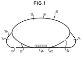
- FIG. 1 schematically shows a double-chamber gas bag 10 according to a first embodiment of the invention.
- This airbag 10 contains a first chamber 12 and a second chamber 14 which is arranged in a generally annular manner around the first chamber.
- the two chambers are formed by a generally circular upper fabric tab 16, the outer periphery of which is connected to the outer periphery of a generally circular lower fabric tab 18.
- a central fabric flap 20 Arranged between the upper and lower fabric flaps 16, 18 is a central fabric flap 20, the outer circumference of which is connected to the upper fabric flap 16 and the central portion 22 of which is connected to the lower fabric flap 18.
- the first chamber 12 is separated from the second chamber 14 by the middle tissue flap 20.
- the middle fabric flap 20 has a schematically illustrated overflow opening 24, via which the first chamber 12 is in flow connection with the second chamber 14, and the lower fabric flap 18 has a schematically illustrated outflow opening 19, through which the second chamber 14 communicates with the outside environment of the Gas bags are in flow connection.
- an inflator 26 is arranged in the interior of the first chamber and, after ignition by a suitable trigger sensor system (not shown), provides a predetermined amount of gas under pressure. After the inflation device 26 has been ignited, the generated gas first flows into the first chamber 12 and then out of it through the overflow opening 24 into the second chamber 14. The gas under pressure can finally flow out of the second chamber 14 through the outflow opening 19 out of the gas bag .
- FIG. 2 shows a double-chamber gas bag 10 according to a second embodiment of the invention.
- the double-chamber gas bag 10 according to the second embodiment an inflator provided for inflating the gas bag is not arranged inside the gas bag.
- the first chamber 12 has an injection opening 30 which is in flow connection with a suitable inflator (not shown). This injection opening 30 extends through the fabric of the lower and that of the middle fabric flap 18 and 20, respectively.
- the inflation process in this double-chamber gas bag also corresponds to the inflation process described with reference to FIG. 1: the pressurized gas generated if necessary flows first into the first chamber 10 and from there into the second chamber 12. From the second chamber 12 can it exit through the outflow opening 19.
- the double chamber gas bag is manufactured in the following way: First, the suitably cut middle fabric flap 20 is connected to the upper fabric flap 16 and the lower fabric flap 18. This is done by sewing the outer circumference of the middle fabric flap 20 to the upper fabric flap 16 by means of a seam 40 running along this outer circumference, and by the border area of the blowing opening 30 of the middle fabric flap 20 using a seam 42 running along this border area with the border area of the blowing opening 30 of the lower flap 18 is sewn. The outer circumference of the upper fabric flap 16 is then sewn to the outer circumference of the lower fabric flap 18 by means of a seam 44.
- FIG. 3 shows a variant of the embodiment in FIG. 2.
- the double-chamber gas bag 10 shown in FIG. 3 differs from the double-chamber gas bag shown in FIG. 2 only in the order in which the various fabric flaps are sewn together.
- the outer circumference of the middle fabric flap 20 is first with the upper one Fabric flap 16 sewn.
- the outer circumference of the lower fabric flap 18 is sewn to the outer circumference of the upper fabric flap 16 such that the lower fabric flap 18 is on the opposite side to the middle fabric flap 20 on the upper fabric flap 16.
- the gas bag is then turned inside out, so that the middle fabric flap 20 lying up to then outside of the gas bag comes to rest inside the double-chamber gas bag 10.
- the border area of the blowing opening 30 of the middle fabric flap 20 is sewn to the border area of the blowing opening 30 of the lower fabric flap 18.
- the configuration of the double-chamber gas bag 10 results in the following advantages:
- the special arrangement of the first chamber 12 relative to the second chamber 14 results in a particularly high dimensional stability of the double-chamber gas bag 10 without the need for tether straps.
- the inflation behavior, the hardness of each chamber that arises during inflation, and the timing of the inflation of the first and second chambers 12, 14 can be adapted to the respective operating conditions by suitable selection of the following parameters: ratio of the volume of the first chamber 12 to second chamber 14, gas permeability of the overflow opening 24 and gas permeability of the outlet opening 19. It is obvious that instead of the illustrated single overflow opening 24 or outlet opening 19, several overflow openings and several outlet openings can also be provided.
- the middle fabric flap 20 and the lower fabric flap 18 consist of fabric with a defined gas permeability behavior. It is thus possible to dispense with the overflow opening 24 in the middle fabric part 20 and the outlet opening 19 in the lower fabric part 18.
- the inflation behavior of the double-chamber gas bag can then be influenced by a suitable selection of the gas permeability of the middle and the lower tissue flap.
- the double-chamber gas bag according to the invention can be manufactured in a particularly simple manner. If, in addition, according to the further development (not shown), gas-permeable fabric is used for the middle fabric flap 20 and the lower fabric flap 18, the production of the double-chamber gas bag is further simplified since no overflow or outflow openings have to be formed.
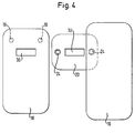
- FIG. 4 shows a schematic top view of the upper fabric flap 16, the lower fabric flap 18 and the middle fabric flap 20 of an airbag according to a third embodiment of the invention.
- This embodiment largely corresponds to the first and second embodiments.
- rectangular tissue flaps are provided in the third embodiment. This is particularly advantageous for a passenger gas bag.
Landscapes
- Engineering & Computer Science (AREA)
- Mechanical Engineering (AREA)
- Air Bags (AREA)
Applications Claiming Priority (2)
| Application Number | Priority Date | Filing Date | Title |
|---|---|---|---|
| DE29518651U | 1995-11-24 | ||
| DE29518651U DE29518651U1 (de) | 1995-11-24 | 1995-11-24 | Doppelkammer-Gassack für ein Fahrzeuginsassen-Rückhaltesystem |
Publications (1)
| Publication Number | Publication Date |
|---|---|
| EP0775614A2 true EP0775614A2 (fr) | 1997-05-28 |
Family
ID=8015867
Family Applications (1)
| Application Number | Title | Priority Date | Filing Date |
|---|---|---|---|
| EP96118274A Withdrawn EP0775614A2 (fr) | 1995-11-24 | 1996-11-14 | Coussin gonflable à deux chambres pour système de retenue pour passager de véhicule |
Country Status (7)
| Country | Link |
|---|---|
| EP (1) | EP0775614A2 (fr) |
| JP (1) | JPH09183358A (fr) |
| KR (1) | KR970026548A (fr) |
| CN (1) | CN1152514A (fr) |
| CZ (1) | CZ283105B6 (fr) |
| DE (1) | DE29518651U1 (fr) |
| ES (1) | ES2104530T1 (fr) |
Cited By (4)
| Publication number | Priority date | Publication date | Assignee | Title |
|---|---|---|---|---|
| US6471244B1 (en) | 1999-04-28 | 2002-10-29 | Nihon Plast Co., Ltd. | Airbag and airbag arrangement |
| EP1140573A4 (fr) * | 1998-12-14 | 2004-12-08 | Breed Automotive Tech | Airbag lat ral pour conducteur |
| US6962363B2 (en) * | 2000-07-07 | 2005-11-08 | Milliken & Company | Multiple chamber airbags and methods |
| US7503582B2 (en) | 2002-05-28 | 2009-03-17 | Takata Corporation | Multipart airbag cutting for an airbag of an occupant protection device for motor vehicles and method for producing an airbag from said airbag cutting |
Families Citing this family (10)
| Publication number | Priority date | Publication date | Assignee | Title |
|---|---|---|---|---|
| US5560649A (en) * | 1995-04-25 | 1996-10-01 | Morton International, Inc. | Air bag cushion having variable volume |
| JP3016746B2 (ja) * | 1996-04-24 | 2000-03-06 | ペトリ・アーゲー | ガスバッグ |
| DE29608055U1 (de) * | 1996-04-24 | 1996-07-18 | Daimler Benz Ag | Gassack, insbesondere für ein Seitenairbagmodul |
| DE19645401A1 (de) * | 1996-11-04 | 1998-05-20 | Audi Ag | Gassack für ein Sicherheitssystem eines Kraftfahrzeugs |
| GB2334492B (en) * | 1997-11-28 | 2002-05-15 | Nihon Plast Co Ltd | Air bag, air bag apparatus, and steering wheel |
| US6626459B2 (en) | 2000-03-31 | 2003-09-30 | Toyoda Gosei Co., Ltd. | Air bag for steering wheel |
| JP4560984B2 (ja) * | 2001-04-13 | 2010-10-13 | タカタ株式会社 | 運転席用エアバッグ装置 |
| US7347445B2 (en) | 2006-05-12 | 2008-03-25 | Hyundai Motor Company | Vehicle airbag device with an auxiliary chamber |
| DE202018101242U1 (de) | 2018-03-06 | 2019-06-07 | Trw Automotive Safety Systems Gmbh | Gassack sowie Gassackmodul für ein Kraftfahrzeug mit einem solchen Gassack |
| DE102022100934A1 (de) | 2022-01-17 | 2023-07-20 | Zf Automotive Germany Gmbh | Beingassack, Fahrzeug und Fahrzeugsitz |
Family Cites Families (2)
| Publication number | Priority date | Publication date | Assignee | Title |
|---|---|---|---|---|
| JPS522527B2 (fr) * | 1972-12-20 | 1977-01-22 | ||
| JPH07223502A (ja) * | 1994-02-07 | 1995-08-22 | Ikeda Bussan Co Ltd | エアバッグ装置のエアバッグ本体 |
-
1995
- 1995-11-24 DE DE29518651U patent/DE29518651U1/de not_active Expired - Lifetime
-
1996
- 1996-11-14 ES ES96118274T patent/ES2104530T1/es active Pending
- 1996-11-14 EP EP96118274A patent/EP0775614A2/fr not_active Withdrawn
- 1996-11-15 KR KR1019960054548A patent/KR970026548A/ko not_active Ceased
- 1996-11-22 JP JP8311765A patent/JPH09183358A/ja active Pending
- 1996-11-22 CZ CZ963434A patent/CZ283105B6/cs unknown
- 1996-11-22 CN CN96114584A patent/CN1152514A/zh active Pending
Non-Patent Citations (1)
| Title |
|---|
| None |
Cited By (4)
| Publication number | Priority date | Publication date | Assignee | Title |
|---|---|---|---|---|
| EP1140573A4 (fr) * | 1998-12-14 | 2004-12-08 | Breed Automotive Tech | Airbag lat ral pour conducteur |
| US6471244B1 (en) | 1999-04-28 | 2002-10-29 | Nihon Plast Co., Ltd. | Airbag and airbag arrangement |
| US6962363B2 (en) * | 2000-07-07 | 2005-11-08 | Milliken & Company | Multiple chamber airbags and methods |
| US7503582B2 (en) | 2002-05-28 | 2009-03-17 | Takata Corporation | Multipart airbag cutting for an airbag of an occupant protection device for motor vehicles and method for producing an airbag from said airbag cutting |
Also Published As
| Publication number | Publication date |
|---|---|
| JPH09183358A (ja) | 1997-07-15 |
| CZ343496A3 (en) | 1997-06-11 |
| DE29518651U1 (de) | 1996-02-22 |
| ES2104530T1 (es) | 1997-10-16 |
| KR970026548A (ko) | 1997-06-24 |
| CN1152514A (zh) | 1997-06-25 |
| CZ283105B6 (cs) | 1998-01-14 |
Similar Documents
| Publication | Publication Date | Title |
|---|---|---|
| EP0590518B1 (fr) | Coussin d'air gonflable de collision de flanc pour un système de retenue dans un véhicule | |
| DE19931028B4 (de) | Aufblasbare Fahrzeuginsassenschutzvorrichtung | |
| DE69407069T2 (de) | Insassen-Luftsackrückhaltevorrichtung | |
| DE69623795T2 (de) | Seitenaufprall-luftsack | |
| DE69113495T2 (de) | Aufbau und Verfahren zum Zusammenbau eines Airbagmoduls. | |
| DE19856407B4 (de) | Beifahrer-Airbagvorrichtung | |
| EP1219508B1 (fr) | Module de sac gonflable | |
| DE69310859T2 (de) | Gefaltetes Luftkissen | |
| DE60023205T2 (de) | Luftsack | |
| DE69924295T2 (de) | Seitenairbagsystem | |
| DE19742151B4 (de) | Seitenaufprall-Airbagsystem | |
| EP2424750B1 (fr) | Module de coussin gonflable pour protéger la région du thorax et la tête d'un occupant de véhicule | |
| EP1140569B1 (fr) | Module airbag | |
| DE19719159A1 (de) | Luftsack für eine Luftsackvorrichtung | |
| EP1231115B1 (fr) | Module d'airbag | |
| DE19847854A1 (de) | Zweikammerluftsack | |
| DE19911082B4 (de) | Vorrichtung für eine aufblasbare Fahrzeuginsassenschutzvorrichtung | |
| EP1008494A2 (fr) | Dispositif à coussin gonflable de protection contre les chocs latéraux | |
| EP0771698A2 (fr) | Dispositif de protection contre les chocs latéraux à coussin gonflable | |
| DE29818946U1 (de) | Gassack für ein Fahrzeuginsassen-Rückhaltesystem | |
| DE10164161A1 (de) | Airbagvorrichtung für einen Fahrgastsitz | |
| DE19858690A1 (de) | Luftsack | |
| DE29713112U1 (de) | Gassack-Rückhaltesystem | |
| WO2008061888A1 (fr) | Sac à gaz pour un véhicule automobile | |
| EP0584782A1 (fr) | Système de retenue à coussin d'air pour véhicules |
Legal Events
| Date | Code | Title | Description |
|---|---|---|---|
| PUAI | Public reference made under article 153(3) epc to a published international application that has entered the european phase |
Free format text: ORIGINAL CODE: 0009012 |
|
| AK | Designated contracting states |
Kind code of ref document: A2 Designated state(s): DE ES FR GB IT SE |
|
| GBC | Gb: translation of claims filed (gb section 78(7)/1977) | ||
| EL | Fr: translation of claims filed | ||
| REG | Reference to a national code |
Ref country code: ES Ref legal event code: BA2A Ref document number: 2104530 Country of ref document: ES Kind code of ref document: T1 |
|
| RAP1 | Party data changed (applicant data changed or rights of an application transferred) |
Owner name: TRW OCCUPANT RESTRAINT SYSTEMS GMBH & CO. KG |
|
| STAA | Information on the status of an ep patent application or granted ep patent |
Free format text: STATUS: THE APPLICATION IS DEEMED TO BE WITHDRAWN |
|
| 18D | Application deemed to be withdrawn |
Effective date: 19990601 |