EP0775801A2 - Faltbare Struktur - Google Patents
Faltbare Struktur Download PDFInfo
- Publication number
- EP0775801A2 EP0775801A2 EP97200450A EP97200450A EP0775801A2 EP 0775801 A2 EP0775801 A2 EP 0775801A2 EP 97200450 A EP97200450 A EP 97200450A EP 97200450 A EP97200450 A EP 97200450A EP 0775801 A2 EP0775801 A2 EP 0775801A2
- Authority
- EP
- European Patent Office
- Prior art keywords
- lateral supports
- plateau
- folded
- another
- out position
- Prior art date
- Legal status (The legal status is an assumption and is not a legal conclusion. Google has not performed a legal analysis and makes no representation as to the accuracy of the status listed.)
- Withdrawn
Links
- 230000007704 transition Effects 0.000 claims description 3
- 230000000284 resting effect Effects 0.000 abstract 1
- 230000000295 complement effect Effects 0.000 description 3
- 230000002349 favourable effect Effects 0.000 description 2
- 238000005406 washing Methods 0.000 description 1
Images

Classifications
-
- E—FIXED CONSTRUCTIONS
- E06—DOORS, WINDOWS, SHUTTERS, OR ROLLER BLINDS IN GENERAL; LADDERS
- E06C—LADDERS
- E06C1/00—Ladders in general
- E06C1/02—Ladders in general with rigid longitudinal member or members
- E06C1/38—Special constructions of ladders, e.g. ladders with more or less than two longitudinal members, ladders with movable rungs or other treads, longitudinally-foldable ladders
- E06C1/39—Ladders having platforms; Ladders changeable into platforms
- E06C1/393—Ladders having platforms foldable with the ladder
Definitions
- the invention relates to a folding structure comprising at least two supporting elements that are connected to one another by means of a hinge joint allowing movement between a folded position and a folded-out position, which supporting elements each comprise two parallel lateral supports that are connected to one another by at least one transverse support and also a plateau, which is rotably connected to each pair of lateral supports and which, in the folded-out position, constitutes a horizontal bearing surface between the lateral supports.
- the aim of the invention is to provide a folding structure that does not possess this drawback, or that possesses it to a lesser extent.
- the structure according to the invention may be for example steps or a step-stool, but also a piece of furniture, for example a folding table or chair, with the tabletop or the seat, respectively, constituting the plateau and the legs two by two serving as the lateral supports of the supporting elements.
- the structure according to the invention may furthermore also be embodied in for example a folding washing rack and in a general sense in any folding structure which in folded-out condition has a horizontal part that is subjected to a vertical load.
- the structure according to the invention can be folded and has a folded and a folded-out position.
- the structure In the folded-out position the structure is in the form suitable for the function of use.
- the structure In the folded position the structure is generally a flat package that takes up the smallest possible volume.
- the supporting elements In the folded position the supporting elements are practically parallel to one another, with the other elements incorporated between them, projecting as little as possible beyond the supporting elements.
- Each supporting element comprises two lateral supports that run parallel to one another.
- 'Parallel' is here also understood to mean 'at a small angle relative to one another in the plane defined by the lateral supports', for example up to 10 -15°. Setting the lateral supports at a certain angle, so that the ends of the lateral supports which rest on the ground when the structure is used are further removed from one another than the other ends, enlarges the supporting area on the ground delimited by the lateral supports, which has a favourable effect on the structure's stability.
- the lateral supports may to this end also include a bend or curvature.
- the lateral supports are connected to one another by at least one transverse support.
- transverse support contributes to the structure's sturdiness and prevents the lateral supports being forced apart on the ground when they are loaded, which could cause the structure to collapse.
- steps the individual steps will usually serve as the transverse supports.
- the transverse support may be of a relatively light design because the vertical load to which it is exposed will generally be lower than with steps, a stool or a chair.
- the supporting elements are connected to one another, usually via the lateral supports, by means of hinges so that they can move relative to one another.
- These hinges may be in the vicinity of the ends of the lateral supports, as a result of which the structure will in folded-out condition have the shape of a V with its opening facing downwards, or more in the direction of the middle of one or both of the lateral supports, as a result of which the folded-out structure will have the shape of an X or the shape of the Greek letter ⁇ .
- the hinges may be attached to a shaft connecting the lateral supports of each of the supporting elements, which shaft then runs parallel to the direction of the transverse support.
- the hinges may also be incorporated in the lateral supports without being connected to one another. If, in the structure's folded-out position, the hinge points are at a short distance above the position of the plateau, the latter embodiment is preferable.
- the plateau in a folding structure is usually fitted between the lateral supports, parallel to the transverse support. In the folded-out condition the plateau assumes a horizontal position, hence constituting a sitting, standing or bearing surface.
- 'Horizontal' is here also understood to mean 'at a small angle relative to horizontal'.
- 'At a small angle' is here understood to be an angle of at most 10 - 15°.
- a plateau that is as horizontal as possible is desirable so as to prevent the user slipping from the plateau.
- the tabletop of a folding table is preferably horizontal. If the folding structure is a chair, a slightly backwards-sloping position of the plateau, in this case the sitting element, will have a considerable favourable effect on the sitting comfort.
- the plateau is rotably connected to the two lateral supports of each of the supporting elements. Often the plateau is only rotably connected to the two lateral supports of one of the supporting elements, hereinafter to be referred to as the first supporting element, and is connected to the lateral supports of the other supporting element, hereinafter to be referred to as the second supporting element, in a fashion that allows both rotation and vertical movement.
- the connections with the lateral supports of the first supporting element are then for example formed by round pins which are, optionally with bearings, rotably incorporated in holes or cavities made in the sides facing one another of that supporting element's two lateral supports.
- the connection between the plateau and the second supporting element may be designed in several manners known per se.
- An example of a suitable embodiment is known from EP-A-457,703.
- a bar on both sides of the plateau one end of which is rotably connected to one of the lateral supports of the second supporting element, the other end being rotably connected to one side of the plateau.
- the plateau In folded-out condition the plateau is then on one side, parallel to the transverse support, supported by the connections with the lateral support of one supporting element, in particular by the hinge pins, and on the opposite side the plateau rests on parts of the hinge structure projecting beyond the lateral supports at the bars' connections.
- the plateau When the structure is folded, the plateau is pressed upwards by the bars, which are connected to the lateral supports of the second supporting element, and rotates around the axis through the plateau's connections with the lateral supports of the first supporting element until the plateau is ultimately, in the folded position, practically vertical between the lateral supports.
- Another known embodiment for the connection of the plateau with the lateral supports of the second supporting element is the one with a groove in the sides facing one another of the lateral supports of the second supporting element, in which groove a pin present on each of the sides of the plateau is incorporated in a manner allowing a sliding movement and rotation.
- the pins In the folded-out position the pins rest on the lowest part of the grooves' wall.
- the pins slide through the grooves in the direction of the top end of those grooves, the plateau again rotating around the axis through the connections with the lateral supports of the first supporting element.
- the plateau rises from the horizontal position until it is ultimately, in the folded condition, practically vertical between the lateral supports.
- the plateau rests directly or indirectly, which is understood to mean via parts that are connected to the hinge pins so that forces exerted on these parts are transmitted to the hinge pins, on the hinge pins, which must bear the load.
- these hinge pins are unloaded in the folded-out position because the load is directly borne by the lateral supports and is not transmitted to the hinge structure.
- the plateau hence rests directly on the lateral supports and not on hinge pins or on parts that are connected to them so that the plateau's load is transmitted via the hinge pins after all.
- the plateau in the structure according to the invention may for example rest on projections of the lateral supports, which are then dimensioned so that when the structure is folded out the plateau comes into contact with the projections and comes to rest on them before the hinge pins can be loaded. It is then advantageous if the pins fit into the holes or cavities in which they rotate with a certain amount of spare room. A suitable difference in diameter between the pin and the hole or cavity will depend on the structure's overall size and will lie between 0.05 and 1 mm.
- the plateau rests on provisions that are integrated in the lateral supports.
- a suitable example of this are lateral supports of which one part, hereinafter to be referred to as the bottom part, is thicker than a part lying higher up, hereinafter to be referred to as the top part.
- the bottom part projects relative to the top part, preferably on the inside, the projecting part then constituting a supporting surface.
- Integrated supporting surfaces present the advantage of greater strength over projections and hence the risk of the projections snapping is avoided.
- the plateau therefore rests on supporting surfaces integrated in the lateral supports.
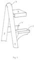
- Fig. 1 is one of the lateral supports of the supporting element referred to as 'first' above, which furthermore consists of transverse support 2 and a complementary, second lateral support, not represented in this figure and designed in mirror image relative to lateral support 1, parallel to lateral support 1, to which it is connected by transverse support 2.
- the other supporting element referred to as 'second' above, consists of lateral support 3 and a second lateral support, designed in mirror image relative to lateral support 3, not represented in the figure, which is connected to the first lateral support 3 by transverse support 4.
- Lateral supports 1 and 3 are connected to one another via a hinge structure at the top 5.
- the hinge structure at the top 5 does not form part of the invention and can be for example a simple tenon and mortise structure.
- 6 stands for the step-stool's plateau. This is horizontal and is connected to the lateral supports 1 and 3 and the not represented complementary lateral supports as further elucidated in the following figures.
- Transverse support 2 is of a different shape than transverse support 4.
- Transverse support 4 is solely intended to serve as a connection between the lateral supports of the supporting element in question to thus grant the structure sturdiness, while transverse support 2 has a flat top side and serves as an intermediate step in stepping onto the stool.
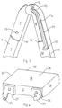
- 7 and 8 are the top parts of the insides, by which are meant the sides facing one another of lateral supports 1 and 3, respectively. They adjoin one another, lying in a single plane, at the top 5.
- the bottom parts of these insides are referred to by 9 and 10, respectively.
- the stepped transition or projection constitutes a supporting surface at right angles to the insides of lateral supports 1 and 3.
- top part 7 there is a round pin 13, which can be rotably incorporated in an opening in the side of the plateau, as will be elucidated with reference to Fig. 4.
- a round pin 13 On the top part 8 of lateral support 3 is an uninterrupted raised wall 14 that borders a groove 15 with a top and bottom end 16 and 17, respectively.
- a pin present on the side of plateau 6, as will become evident from the explanation of Fig. 4, can be incorporated in this groove in a manner allowing movement.
- Fig. 4 6 is a plateau that can be incorporated in a manner allowing rotation and movement in the assembly of which half is represented in Fig. 1.
- the plateau consists of a top surface 18, a front surface 19 and a rear surface 20, not visible in the figure, and two side surfaces 21 and 22 (the latter not visible in the figure).
- pin 25 is incorporated in groove 15 of lateral support 3, while pin 13 of lateral support 1 is incorporated in cavity 26.
- the difference in diameter between pin 13 and cavity 26 is 0.2 mm, the difference in diameter between pin 25 and groove 15 is 0.5 mm.
- Elevation 23 has a flat part 27 at the bottom side and elevation 24 has a flat part 28.
- this flat part 27 rests on supporting surface 12 of lateral support 3, while pin 25 is, as a result of the aforementioned 0.5 mm difference in diameter, not in contact with the base of the groove at the groove's bottom end 17.
- the directions of the flat parts 27 and 28 relative to the plane of the top side of the plateau have been chosen to be such that, in the stool's folded-out position, these directions coincide with the directions of supporting surfaces 12 and 11, respectively, and the top side of the plateau assumes the desired position, generally the horizontal one.
- the connection between side 22 of the plateau and the other pair of lateral supports connected to one another is analogous but designed in mirror image.
Landscapes
- Invalid Beds And Related Equipment (AREA)
- Prostheses (AREA)
- Air Bags (AREA)
- Dry Shavers And Clippers (AREA)
- Toys (AREA)
- Pivots And Pivotal Connections (AREA)
- Agricultural Machines (AREA)
- Absorbent Articles And Supports Therefor (AREA)
- Accommodation For Nursing Or Treatment Tables (AREA)
- Tables And Desks Characterized By Structural Shape (AREA)
- Tents Or Canopies (AREA)
Priority Applications (6)
| Application Number | Priority Date | Filing Date | Title |
|---|---|---|---|
| EP97200450A EP0775801A3 (de) | 1997-02-13 | 1997-02-13 | Faltbare Struktur |
| DE69700227T DE69700227T2 (de) | 1997-02-13 | 1997-08-21 | Faltbare Struktur |
| EP97202561A EP0859118B1 (de) | 1997-02-13 | 1997-08-21 | Faltbare Struktur |
| AT97202561T ATE180312T1 (de) | 1997-02-13 | 1997-08-21 | Faltbare struktur |
| DK97202561T DK0859118T3 (da) | 1997-02-13 | 1997-08-21 | Foldestruktur |
| ES97202561T ES2135282T3 (es) | 1997-02-13 | 1997-08-21 | Estructura plegable. |
Applications Claiming Priority (1)
| Application Number | Priority Date | Filing Date | Title |
|---|---|---|---|
| EP97200450A EP0775801A3 (de) | 1997-02-13 | 1997-02-13 | Faltbare Struktur |
Publications (2)
| Publication Number | Publication Date |
|---|---|
| EP0775801A2 true EP0775801A2 (de) | 1997-05-28 |
| EP0775801A3 EP0775801A3 (de) | 1997-09-10 |
Family
ID=8228020
Family Applications (2)
| Application Number | Title | Priority Date | Filing Date |
|---|---|---|---|
| EP97200450A Withdrawn EP0775801A3 (de) | 1997-02-13 | 1997-02-13 | Faltbare Struktur |
| EP97202561A Expired - Lifetime EP0859118B1 (de) | 1997-02-13 | 1997-08-21 | Faltbare Struktur |
Family Applications After (1)
| Application Number | Title | Priority Date | Filing Date |
|---|---|---|---|
| EP97202561A Expired - Lifetime EP0859118B1 (de) | 1997-02-13 | 1997-08-21 | Faltbare Struktur |
Country Status (5)
| Country | Link |
|---|---|
| EP (2) | EP0775801A3 (de) |
| AT (1) | ATE180312T1 (de) |
| DE (1) | DE69700227T2 (de) |
| DK (1) | DK0859118T3 (de) |
| ES (1) | ES2135282T3 (de) |
Family Cites Families (2)
| Publication number | Priority date | Publication date | Assignee | Title |
|---|---|---|---|---|
| US1517676A (en) * | 1923-01-09 | 1924-12-02 | James G Haugh | Stepladder |
| US1537221A (en) * | 1924-04-17 | 1925-05-12 | George H Bugenhagen | Ladder stool |
-
1997
- 1997-02-13 EP EP97200450A patent/EP0775801A3/de not_active Withdrawn
- 1997-08-21 EP EP97202561A patent/EP0859118B1/de not_active Expired - Lifetime
- 1997-08-21 DK DK97202561T patent/DK0859118T3/da active
- 1997-08-21 AT AT97202561T patent/ATE180312T1/de not_active IP Right Cessation
- 1997-08-21 ES ES97202561T patent/ES2135282T3/es not_active Expired - Lifetime
- 1997-08-21 DE DE69700227T patent/DE69700227T2/de not_active Expired - Fee Related
Also Published As
| Publication number | Publication date |
|---|---|
| ES2135282T3 (es) | 1999-10-16 |
| DE69700227T2 (de) | 1999-11-11 |
| DE69700227D1 (de) | 1999-06-24 |
| ATE180312T1 (de) | 1999-06-15 |
| EP0859118B1 (de) | 1999-05-19 |
| EP0859118A1 (de) | 1998-08-19 |
| DK0859118T3 (da) | 1999-11-22 |
| EP0775801A3 (de) | 1997-09-10 |
Similar Documents
| Publication | Publication Date | Title |
|---|---|---|
| US5975626A (en) | Cross-member supporter for foldable furniture | |
| US4976492A (en) | Foldable outdoor chair | |
| US5580127A (en) | Chair with tilting backrest | |
| US20040251718A1 (en) | Folding chair | |
| US6203101B1 (en) | Office chair armrest device | |
| WO1986000206A1 (en) | Folding chair and table structure | |
| US4089084A (en) | Internal hinge | |
| US7828117B2 (en) | Foldable chair and ladder combination | |
| US6186591B1 (en) | Table with self-adjusting midframe support | |
| KR100267160B1 (ko) | 접철식 의자 | |
| EP0775801A2 (de) | Faltbare Struktur | |
| US20040255829A1 (en) | Portable folding table | |
| GB2098471A (en) | Improvements in or relating to a chair | |
| US2991123A (en) | Folding chair | |
| US4108490A (en) | Foldable chair | |
| EP3697262B1 (de) | Sitzmodul | |
| US5542739A (en) | Folding furniture | |
| GB2043143A (en) | Combined chair and step-ladder | |
| JP2021142212A (ja) | 椅子の座板の支持機構 | |
| KR102115033B1 (ko) | 팔걸이부가 착탈 가능하게 연결되는 의자 | |
| CN224179338U (zh) | 双凹槽折叠支撑装置 | |
| CN218474337U (zh) | 一种摇椅及其底座骨架 | |
| KR102293021B1 (ko) | 의자 | |
| CN223787346U (zh) | 一种折叠椅 | |
| CN220860253U (zh) | 一种折叠轮椅 |
Legal Events
| Date | Code | Title | Description |
|---|---|---|---|
| PUAI | Public reference made under article 153(3) epc to a published international application that has entered the european phase |
Free format text: ORIGINAL CODE: 0009012 |
|
| 17P | Request for examination filed |
Effective date: 19970213 |
|
| AK | Designated contracting states |
Kind code of ref document: A2 Designated state(s): AT BE CH DE DK ES FI FR GB GR IE IT LI LU MC NL PT SE |
|
| PUAL | Search report despatched |
Free format text: ORIGINAL CODE: 0009013 |
|
| AK | Designated contracting states |
Kind code of ref document: A3 Designated state(s): AT BE CH DE DK ES FI FR GB GR IE IT LI LU MC NL PT SE |
|
| STAA | Information on the status of an ep patent application or granted ep patent |
Free format text: STATUS: THE APPLICATION HAS BEEN WITHDRAWN |
|
| 17Q | First examination report despatched |
Effective date: 19970904 |
|
| 18W | Application withdrawn |
Withdrawal date: 19970908 |