EP0775918A2 - Sende- und Empfangssystem - Google Patents
Sende- und Empfangssystem Download PDFInfo
- Publication number
- EP0775918A2 EP0775918A2 EP96118717A EP96118717A EP0775918A2 EP 0775918 A2 EP0775918 A2 EP 0775918A2 EP 96118717 A EP96118717 A EP 96118717A EP 96118717 A EP96118717 A EP 96118717A EP 0775918 A2 EP0775918 A2 EP 0775918A2
- Authority
- EP
- European Patent Office
- Prior art keywords
- signal
- time
- transponder
- answer
- transmitter
- Prior art date
- Legal status (The legal status is an assumption and is not a legal conclusion. Google has not performed a legal analysis and makes no representation as to the accuracy of the status listed.)
- Withdrawn
Links
Images


Classifications
-
- H—ELECTRICITY
- H04—ELECTRIC COMMUNICATION TECHNIQUE
- H04B—TRANSMISSION
- H04B1/00—Details of transmission systems, not covered by a single one of groups H04B3/00 - H04B13/00; Details of transmission systems not characterised by the medium used for transmission
- H04B1/38—Transceivers, i.e. devices in which transmitter and receiver form a structural unit and in which at least one part is used for functions of transmitting and receiving
- H04B1/40—Circuits
-
- G—PHYSICS
- G01—MEASURING; TESTING
- G01S—RADIO DIRECTION-FINDING; RADIO NAVIGATION; DETERMINING DISTANCE OR VELOCITY BY USE OF RADIO WAVES; LOCATING OR PRESENCE-DETECTING BY USE OF THE REFLECTION OR RERADIATION OF RADIO WAVES; ANALOGOUS ARRANGEMENTS USING OTHER WAVES
- G01S13/00—Systems using the reflection or reradiation of radio waves, e.g. radar systems; Analogous systems using reflection or reradiation of waves whose nature or wavelength is irrelevant or unspecified
- G01S13/74—Systems using reradiation of radio waves, e.g. secondary radar systems; Analogous systems
- G01S13/75—Systems using reradiation of radio waves, e.g. secondary radar systems; Analogous systems using transponders powered from received waves, e.g. using passive transponders, or using passive reflectors
- G01S13/751—Systems using reradiation of radio waves, e.g. secondary radar systems; Analogous systems using transponders powered from received waves, e.g. using passive transponders, or using passive reflectors wherein the responder or reflector radiates a coded signal
- G01S13/758—Systems using reradiation of radio waves, e.g. secondary radar systems; Analogous systems using transponders powered from received waves, e.g. using passive transponders, or using passive reflectors wherein the responder or reflector radiates a coded signal using a signal generator powered by the interrogation signal
-
- B—PERFORMING OPERATIONS; TRANSPORTING
- B60—VEHICLES IN GENERAL
- B60R—VEHICLES, VEHICLE FITTINGS, OR VEHICLE PARTS, NOT OTHERWISE PROVIDED FOR
- B60R25/00—Fittings or systems for preventing or indicating unauthorised use or theft of vehicles
- B60R25/01—Fittings or systems for preventing or indicating unauthorised use or theft of vehicles operating on vehicle systems or fittings, e.g. on doors, seats or windscreens
- B60R25/04—Fittings or systems for preventing or indicating unauthorised use or theft of vehicles operating on vehicle systems or fittings, e.g. on doors, seats or windscreens operating on the propulsion system, e.g. engine or drive motor
-
- G—PHYSICS
- G07—CHECKING-DEVICES
- G07C—TIME OR ATTENDANCE REGISTERS; REGISTERING OR INDICATING THE WORKING OF MACHINES; GENERATING RANDOM NUMBERS; VOTING OR LOTTERY APPARATUS; ARRANGEMENTS, SYSTEMS OR APPARATUS FOR CHECKING NOT PROVIDED FOR ELSEWHERE
- G07C9/00—Individual registration on entry or exit
- G07C9/00174—Electronically operated locks; Circuits therefor; Nonmechanical keys therefor, e.g. passive or active electrical keys or other data carriers without mechanical keys
- G07C9/00309—Electronically operated locks; Circuits therefor; Nonmechanical keys therefor, e.g. passive or active electrical keys or other data carriers without mechanical keys operated with bidirectional data transmission between data carrier and locks
-
- G—PHYSICS
- G07—CHECKING-DEVICES
- G07C—TIME OR ATTENDANCE REGISTERS; REGISTERING OR INDICATING THE WORKING OF MACHINES; GENERATING RANDOM NUMBERS; VOTING OR LOTTERY APPARATUS; ARRANGEMENTS, SYSTEMS OR APPARATUS FOR CHECKING NOT PROVIDED FOR ELSEWHERE
- G07C9/00—Individual registration on entry or exit
- G07C9/00174—Electronically operated locks; Circuits therefor; Nonmechanical keys therefor, e.g. passive or active electrical keys or other data carriers without mechanical keys
- G07C2009/00753—Electronically operated locks; Circuits therefor; Nonmechanical keys therefor, e.g. passive or active electrical keys or other data carriers without mechanical keys operated by active electrical keys
- G07C2009/00769—Electronically operated locks; Circuits therefor; Nonmechanical keys therefor, e.g. passive or active electrical keys or other data carriers without mechanical keys operated by active electrical keys with data transmission performed by wireless means
- G07C2009/00777—Electronically operated locks; Circuits therefor; Nonmechanical keys therefor, e.g. passive or active electrical keys or other data carriers without mechanical keys operated by active electrical keys with data transmission performed by wireless means by induction
Definitions
- the present invention relates to a transmission-reception system including a transmitter-receiver device for transmitting a power signal and an enquiry signal, and a transponder that, upon receiving the enquiry signal and the power signal, sends back an answer signal using the power signal as a power source.
- a motor-vehicle ignition key with an electronic key function using an electric identification code.
- the motor vehicle is correspondingly equipped with a transmission-reception ECU, and when an ignition key as described above is inserted in the ignition keyway and turned to the ON position (or the ACC position), the ECU reads the identification code of the key, and permits the start of the engine by the ignition key only when the read identification code agrees with a predetermined identification code.
- the transmission-reception ECU is provided with an antenna coil disposed around the keyway, so as to perform an interrogator function of transmitting a carrier wave signal and an enquiry signal convoluted with the carrier wave signal from the antenna coil.
- the bow of the ignition key contains a transponder provided with a transponder coil that, when the ignition key is inserted in the keyway, is electromagnetically coupled with the antenna coil.
- the transponder uses as a power source an output provided by rectifying the carrier wave signal received through the transponder coil. When the power rises, the transponder responds to the received enquiry signal by sending back an answer signal including a pre-stored identification code.
- the above-described transmission-reception system uses serial communication. That is, the transmission-reception ECU transmits an enquiry signal formed of a time series pulse signal including time information (for example, a combination of a timing signal train of a fixed cycle and a binary signal train combined with the individual timing signals), which signal is convoluted with a carrier wave signal.
- the transponder decodes the content of the enquiry signal received on the basis of the time information contained therein, and then sends back an answer signal corresponding to the decoding result, in the form of a time series pulse signal.
- transponders for the aforementioned applications are normally constructed by hard logic, resulting in fixed identification codes. Since fixed identification codes are relatively easy to copy or intercept, the conventional art is unable to sufficiently safeguard privacy or security performance against theft.
- a microcomputer is provided in a transponder so that the identification code is enciphered or encoded in various manners using microcomputer control, thus enhancing security. Since size reduction of the transponder becomes important for this measure and costs should usually be curbed, it is conceivable that a CR oscillator, which can easily be miniaturized and is inexpensive, should normally be used as an oscillating circuit that determines the clock frequency of the microcomputer.
- CR oscillating circuits have voltage dependency in that the oscillating frequency decreases as the power voltage decreases, so that the employment of a CR oscillating circuit is likely to cause the following problems.
- the transponder Since the transponder is supplied with power in a non-contact manner through the transponder coil electromagnetically coupled with the antenna coil of a transmitter-receiver device, the power inevitably varies depending on factors including variations in the distance between the transponder coil and the antenna coil, the ambient temperature, and the circuit constants of the electronic components constituting the transponder and the transmission-reception ECU. Variation in the power changes the oscillating frequency of the CR oscillating circuit and, therefore, changes the clock frequency of the microcomputer.
- the transponder suffers inaccurate time management by the microcomputer of the transponder, deteriorating communication performance. For example, errors become likely to occur in the aforementioned decoding of the content of an enquiry signal based on time information.
- a transmission-reception system comprising: a transmitter-receiver device transmitting an enquiry signal formed of a time series pulse signal including time information, together with a power signal, the transmitter-receiver device being constructed to transmit a reference time signal of a fixed time length together with the power signal before transmitting the enquiry signal; and a transponder that is switchable to an active state by the power signal from the transmitter-receiver device, to decode the content of the received enquiry signal on the basis of the time information, and that sends back to the transmitter-receiver device an answer signal in accordance with the result of decoding.
- the transponder comprises a microcomputer for decoding the content of the enquiry signal and controlling the transmission of the answer signal, and a storage portion that stores a value of the reference time.
- the transponder Upon receiving the reference time signal from the transmitter-receiver device, the transponder measures the time length of the reference time signal using a clock signal of the microcomputer, and calculates as a correction coefficient a ratio between the measured time length and the reference time value stored in the storage portion, and, while the microcomputer is decoding the enquiry signal, corrects the time information included in the time series pulse signal forming the received enquiry signal using the correction coefficient.
- the transmitter-receiver device transmits the reference time signal of a fixed time length together with the power signal before transmitting the enquiry signal formed of a time series pulse signal including time information, together with the power signal.
- the transponder measures the time length of the reference time signal using the clock signal of the microcomputer, and calculates, as a correction coefficient, a ratio between the measured time length and the reference time value stored in the storage portion.
- the microcomputer corrects the time information included in the time series pulse signal forming the enquiry signal, using the correction coefficient.
- the microcomputer decodes the content of the enquiry signal while correcting the time information included in the time series pulse signal forming the enquiry signal.
- the transponder is constructed to send back an answer signal formed of a time series pulse signal including time information, and so as to transmit an answer reference time signal of a fixed time length using the clock signal of the microcomputer, prior to an operation of transmitting the answer signal.
- the transmitter-receiver device Upon receiving the answer reference time signal from the transponder, the transmitter-receiver device measures the time length of the answer reference time signal, and calculates as a second correction coefficient a ratio between the measured time length and the time length of the reference time signal, and performs an operation of decoding content of the received answer signal while correcting the time information included in the time series pulse signal forming the answer signal, using the second correction coefficient.
- the transmitter-receiver device is able to precisely perform the operation of decoding the answer signal from the transponder, thus improving communication performance.
- the transmission-reception system in another preferred construction is constructed to send back an answer signal formed of a time series pulse signal including time information, and to send back the aforementioned correction coefficient prior to an operation of transmitting the answer signal, in which the transmitter-receiver device is constructed to perform an operation of decoding content of the answer signal from the transponder while correcting the time information included in the time series pulse signal forming the answer signal using the correction coefficient.
- This preferred construction also enables the transmitter-receiver device to precisely perform the operation of decoding the answer signal, thus improving communication performance.
- the transmission-reception system in still another preferred construction is constructed to send back an answer signal formed of a time series pulse signal including time information that has been corrected by the aforementioned correction coefficient, in which the transmitter-receiver device is constructed to decode the content of the answer signal from the transponder on the basis of the time information included in the time series pulse signal forming the answer signal.
- This preferred construction also enables the transmitter-receiver device to precisely perform the operation of decoding the answer signal, thus improving communication performance.
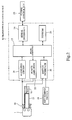
- Fig. 1 illustrates an electrical construction of a transmitter-receiver unit 2 (corresponding to a transponder according to the invention), contained in the bow of an ignition key 1 shown in Fig. 2.
- the transmitter-receiver unit 2 has a microcomputer 3 as a significant component.
- the transmitter-receiver unit 2 Upon receiving a power signal and an enquiry signal from outside, the transmitter-receiver unit 2 responds to the enquiry signal by sending back an answer signal described below.
- the microcomputer 3 contains an EEPROM 4, a resistor 5a of a power-on reset circuit 5, and an n-channel FET 6a of a modulating circuit 6.
- the EEPROM 4 stores an identification code specific to the corresponding ignition key 1, and also stores a function expression for enciphering the identification code, and predetermined reference time values ⁇ Ta, ⁇ Tb, ⁇ Tc, ⁇ Td.
- the reference time values ⁇ Ta, ⁇ Tb, ⁇ Tc, ⁇ Td are expressed as, for example, value data based on the rated clock frequency of the microcomputer 3, that is, value data indicating the clock signal number in the rated frequency.
- the reference time values ⁇ Ta, ⁇ Tb, ⁇ Tc, ⁇ Td are not necessarily stored in the EEPROM 4, but may be pre-stored in a ROM (not shown) provided in the microcomputer 3.
- a resonance circuit portion 7 comprises a transponder coil 8 and a resonance capacitor 9 that are connected in parallel between a signal line SL and a ground terminal.
- the resonance frequency is preset to equal the frequency band of the carrier wave signal (corresponding to the power signal) transmitted from a transmission-reception ECU 10 (shown in Fig. 2) installed as a transmitter-receiver device in the motor vehicle.
- a power circuit 12 connected to the signal line SL by a resistor 11, rectifies and smoothes the carrier wave signal received by the resonance circuit portion 7 and sends the thus-obtained output to a power terminal VDD of the microcomputer 3.
- the power circuit 12 comprises a rectifying diode 12a, a smoothing capacitor 12b, a constant-voltage diode 12c and a resistor 12d that are connected as shown in Fig. 1.
- a detector circuit 13 connected to the signal line SL by the resistor 11, discriminates the reference time signal and enquiry signal supplied together with the carrier wave signal through the resonance circuit portion 7, and sends the discriminated signals to an input port PI of the microcomputer 3.
- the detector circuit 13 comprises a detector diode 13a, a capacitor 13b, and resistors 13c, 13d that are connected as shown in Fig. 1.
- the time constant of the detector circuit 13 is preset to a value less than the charging time constant of the smoothing function portion of the power circuit 12, thus enabling discrimination of the reference time and enquiry signals.
- the modulating circuit 6, comprising the FET 6a, is connected in parallel to the resonance capacitor 9 of the resonance circuit portion 7.
- a modulating capacitor 6b and the source and drain of the FET 6a are connected in series. In accordance with the turning on and off of the FET 6a, the impedance of the resonance circuit portion 7 can be changed.
- the reset circuit 5 performs the power-on reset function of holding the microcomputer 3 in a reset state until the level of power supplied to the power terminal VDD of the microcomputer 3 (the output voltage level of the power circuit 12) reaches a predetermined level or higher.
- the reset circuit 5 comprises a diode 5b, a capacitor 5c and the resistor 5a, which are connected as shown in Fig. 1.
- a CR oscillating circuit 14 comprises a resistor 14a and a capacitor 14b, and determines the clock frequency of the microcomputer 3.
- Fig. 2 schematically illustrates the overall construction of the system of the invention by a combination of the functional blocks.
- an antenna coil 16 is provided around an ignition cylinder 15 of the motor vehicle.
- the antenna coil 16 is electromagnetically coupled with the transponder coil 8 (see Fig. 1) contained in the ignition key 1.
- the transmission-reception ECU 10, provided in the motor vehicle, comprises a microcomputer 17 as a significant component.
- the microcomputer 17 receives on-signals from a key remind switch 19 and an ignition switch 18 provided for the cylinder 15 as is well known in the art, via a switch interface 20.
- the signal received by the antenna coil 16 is inputted to the microcomputer 17 through a receiving circuit 21 that has an amplifying function.
- the microcomputer 17 controls the transmission through the antenna coil 16 by the output from a power amplifier 22.
- the microcomputer 17 sends signals to and receives signals from an engine control ECU 23 through a serial interface 24.
- the microcomputer 17 selectively inhibits the engine control ECU 23 from performing the engine starting operation.
- the microcomputer 17 outputs data to and reads data from an EEPROM 25.
- Pre-stored in the EEPROM 25 are the same identification code and function expression for enciphering the identification code as the identification code and function expression for the encipherment stored in the EEPROM 4 of the ignition key 1 provided corresponding to the motor vehicle.
- the controls by the microcomputer 3 of the transmitter-receiver unit 2 and the microcomputer 17 of the transmission-reception ECU 10 will be described in conjunction with the functions of related components.
- the microcomputer 17 of the transmission-reception ECU 10 When the microcomputer 17 of the transmission-reception ECU 10 receives on-signals from the key remind switch 19 and the ignition switch 18, that is, when the ignition key 1 is inserted into the cylinder 15 and turned to the on-position (in this state, the antenna coil 16 and the transponder coil 8 of the ignition key 1 are electromagnetically coupled), the microcomputer 17 generates new random number data by a predetermined function calculation, and stores the random number data into an internal memory (not shown) such as a RAM. The microcomputer 17 also generates a reference time signal and a pulse-train enquiry signal that includes the random number data, and operates the power amplifier 22 to transmit from the antenna coil 16 a predetermined-frequency carrier wave signal and the reference time signal and enquiry signal, convoluted therewith.
- the reference time signal and the enquiry signal have a form as indicated in Fig. 3A.
- the reference time signal is formed of a combination of a pair of falling pulses Pa1, Pa2 (having a fixed pulse length of Tb) that are outputted at a fixed interval Ta starting at a time point when a predetermined length of time elapses after the start of transmission of a carrier wave signal (actually, a sine wave signal).
- the time interval Ta is used as a time reference by the transmitter-receiver unit 2.
- the enquiry signal has a format including time information provided by a combinations of a train of fixed-interval falling timing pulses Pt and a train of data (in Fig. 3A, the high voltage status expresses data "0", and the low voltage status expresses data "1") formed of binary signals expressed by the carrier wave signal voltage levels occurring during a predetermined time length Tb, after the timing at which a predetermined waiting time Tc has elapsed following the fall of each timing pulse Pt.
- the data train expresses start bit data indicating that the signal is an enquiry signal, and the aforementioned random number data, stop bit data, and the like.
- the timing pulses Pt and the falling pulses in the data train have a fixed pulse length Tb.
- the output interval of the timing pulses Pt is fixed to Td.
- the time interval Ta, the pulse length Tb, the waiting time Tc and the output interval Td of the timing pulses Pt are adjusted to equal the reference time values ⁇ Ta, ⁇ Tb, ⁇ Tc, ⁇ Td, respectively, stored in the EEPROM 4 of the transmitter-receiver unit 2.
- the power circuit 12 of the transmitter-receiver unit 2 rectifies and smoothes the carrier wave and sends the thus-obtained output (the voltage waveform indicated in Fig. 3B) to the power terminal VDD of the microcomputer 3.
- the output voltage reaches the predetermined level or higher, the reset maintenance by the reset circuit 5 is canceled so that the microcomputer 3 switches to the active state.
- the detector circuit 13 discriminates the reference time signal and the enquiry signal, and supplies them to the input port PI of the microcomputer 3.
- the thus-activated microcomputer 3 sequentially performs the control steps or actions (1)-(5) discussed below.
- the starting of the motor vehicle engine by the engine control ECU 23 is allowed if the ignition cylinder 15 receives the correct ignition key 1, so that their identification codes agree with each other.
- the embodiment thus performs a security immobilizer function.
- the embodiment Since the transmitter-receiver unit 2 is constructed so as to send back an enciphered answer signal in response to an enquiry signal from the transmission-reception ECU 10, the embodiment improves security and, therefore, enhances protection against theft of the motor vehicle. Since the encipherment of the answer signal is based on the program of the microcomputer 3, the embodiment enables various encipherment or coding as desired for improvement in security, without complicating hardware construction.
- the transmitter-receiver unit 2 is constructed to employ the CR oscillating circuit 15, which can be easily miniaturized and is inexpensive, as an oscillating circuit for determining the clock frequency of the microcomputer 3, the embodiment prevents size and cost increases.
- the transmission-reception ECU 10 decodes the answer signal from the transmitter-receiver unit 2 while the time reference of the microcomputer 17 is automatically corrected on the basis of the second correction coefficient ⁇ 2.
- the embodiment thus enables the microcomputer 17 to perform precise decoding in such a situation, improving communication performance.
- the transmitter-receiver unit 2 sends back to the transmission-reception ECU 10 the answer reference time signal generated by using the clock signal of the microcomputer 3, and the enciphered answer signal, in that order, it is alternatively possible to send back the correction coefficient ⁇ instead of the answer reference time signal.
- the transmission-reception ECU 10 performs the operation of decoding the content of the answer signal from the transmitter-receiver unit 2 while correcting the time information included in the time series pulse signal forming the answer signal, using the correction coefficient ⁇ .
- the transmitter-receiver unit 2 prefferably produces an answer signal formed of a time series pulse signal including the time information that has been corrected by the correction coefficient ⁇ , and then transmit the thus-corrected answer signal.
- the transmission-reception ECU 10 simply decodes the content of the answer signal from the transmitter-receiver unit 2, on the basis of the time information included in the time series pulse signal forming the answer signal.
- the embodiment employs the CR oscillating circuit 14 to generate the clock signal of the microcomputer 3, other types of oscillating circuits may be used.
- the transmission-reception system of the invention is not limited to the immobilization function of motor vehicles, but may be applied to other types of transmission-reception systems.
Landscapes
- Engineering & Computer Science (AREA)
- Radar, Positioning & Navigation (AREA)
- Remote Sensing (AREA)
- Computer Networks & Wireless Communication (AREA)
- Physics & Mathematics (AREA)
- General Physics & Mathematics (AREA)
- Mechanical Engineering (AREA)
- Signal Processing (AREA)
- Lock And Its Accessories (AREA)
- Selective Calling Equipment (AREA)
- Mobile Radio Communication Systems (AREA)
- Near-Field Transmission Systems (AREA)
- Radar Systems Or Details Thereof (AREA)
Applications Claiming Priority (3)
| Application Number | Priority Date | Filing Date | Title |
|---|---|---|---|
| JP30413395 | 1995-11-22 | ||
| JP30413395A JPH09142257A (ja) | 1995-11-22 | 1995-11-22 | 送受信システム |
| JP304133/95 | 1995-11-22 |
Publications (2)
| Publication Number | Publication Date |
|---|---|
| EP0775918A2 true EP0775918A2 (de) | 1997-05-28 |
| EP0775918A3 EP0775918A3 (de) | 2000-06-28 |
Family
ID=17929445
Family Applications (1)
| Application Number | Title | Priority Date | Filing Date |
|---|---|---|---|
| EP96118717A Withdrawn EP0775918A3 (de) | 1995-11-22 | 1996-11-21 | Sende- und Empfangssystem |
Country Status (4)
| Country | Link |
|---|---|
| US (1) | US5838254A (de) |
| EP (1) | EP0775918A3 (de) |
| JP (1) | JPH09142257A (de) |
| KR (1) | KR100387140B1 (de) |
Cited By (6)
| Publication number | Priority date | Publication date | Assignee | Title |
|---|---|---|---|---|
| FR2752651A1 (fr) * | 1996-08-26 | 1998-02-27 | Siemens Ag | Circuit pour realiser une oscillation modulee en amplitude |
| EP0892358A3 (de) * | 1997-07-18 | 2000-06-28 | Anatoli Stobbe | Verfahren zur Datenübertragung zwischen einem Schreib-Lesegerät und einem Transponder |
| EP0936331A3 (de) * | 1998-02-12 | 2001-08-29 | Mitsuba Corporation | Code Prüfungssystem |
| WO2002050782A3 (en) * | 2000-12-19 | 2003-01-30 | Azoteq Pty Ltd | Method of and apparatus for transferring data |
| GB2384648A (en) * | 2002-01-25 | 2003-07-30 | Intellident Ltd | Tagging system |
| EP1182314A3 (de) * | 2000-08-23 | 2005-01-26 | Siemens VDO Automotive Corporation | Steuerung von Fernsignalübertragung mit Kompensierung von Schwankungen in Komponenten eines Senders |
Families Citing this family (11)
| Publication number | Priority date | Publication date | Assignee | Title |
|---|---|---|---|---|
| SG76615A1 (en) * | 1999-04-16 | 2000-11-21 | Univ Singapore | An rf transponder |
| DE10004922A1 (de) * | 2000-02-04 | 2001-08-09 | Giesecke & Devrient Gmbh | Transponder, insbesondere für eine kontaktlose Chipkarte |
| DE10323402B3 (de) * | 2003-05-23 | 2005-01-05 | Siemens Ag | Zugangs- und Benutzungsberechtigungssystem, insbesondere eines Kraftfahrzeuges |
| GB2423674A (en) * | 2005-02-25 | 2006-08-30 | Hewlett Packard Development Co | Writing to transponder devices |
| GB2463074B (en) * | 2008-09-02 | 2010-12-22 | Ip Access Ltd | Communication unit and method for selective frequency synchronisation in a cellular communication network |
| FR2967538B1 (fr) * | 2010-11-16 | 2013-11-01 | St Microelectronics Rousset | Procede pour moduler l'impedance d'un circuit d'antenne |
| US8750444B2 (en) | 2011-05-06 | 2014-06-10 | Northrop Grumman Systems Corporation | Snapshot processing of timing data |
| DE102012110537A1 (de) * | 2012-11-05 | 2014-05-08 | Endress + Hauser Conducta Gesellschaft für Mess- und Regeltechnik mbH + Co. KG | Verfahren zur Datenübertragung |
| JP6851986B2 (ja) * | 2015-12-21 | 2021-03-31 | 株式会社小糸製作所 | 車両用画像取得装置、制御装置、車両用画像取得装置または制御装置を備えた車両および車両用画像取得方法 |
| KR102812909B1 (ko) | 2019-08-16 | 2025-05-26 | 구글 엘엘씨 | 멀티-칩 시스템의 동기화 |
| CN114460222B (zh) * | 2022-01-28 | 2023-11-17 | 青海青乐化工机械有限责任公司 | 发烟罐的发烟时间测试装置 |
Family Cites Families (7)
| Publication number | Priority date | Publication date | Assignee | Title |
|---|---|---|---|---|
| US4852090A (en) * | 1987-02-02 | 1989-07-25 | Motorola, Inc. | TDMA communications system with adaptive equalization |
| US4803703A (en) * | 1987-04-30 | 1989-02-07 | Motorola, Inc. | Apparatus and method for fine synchronization of a communication receiver |
| JP2767816B2 (ja) * | 1987-10-07 | 1998-06-18 | セイコーエプソン株式会社 | リモコン送信・受信装置 |
| FR2635809B1 (fr) * | 1988-08-24 | 1990-11-23 | Samokine Georges | Systeme d'echange d'informations entre un objet portatif comme une cle, et un dispositif d'echange |
| IT1249903B (it) * | 1991-06-07 | 1995-03-30 | Trw Sipea Spa | Telecomando a sicurezza ottimizzata |
| DE4130903A1 (de) * | 1991-09-17 | 1993-03-18 | Bks Gmbh | Einrichtung zur beruehrungslosen energie- und datenuebertragung |
| US5276706A (en) * | 1992-05-20 | 1994-01-04 | Hughes Aircraft Company | System and method for minimizing frequency offsets between digital communication stations |
-
1995
- 1995-11-22 JP JP30413395A patent/JPH09142257A/ja active Pending
-
1996
- 1996-11-01 KR KR1019960051502A patent/KR100387140B1/ko not_active Expired - Fee Related
- 1996-11-21 EP EP96118717A patent/EP0775918A3/de not_active Withdrawn
- 1996-11-21 US US08/754,799 patent/US5838254A/en not_active Expired - Lifetime
Non-Patent Citations (1)
| Title |
|---|
| None |
Cited By (8)
| Publication number | Priority date | Publication date | Assignee | Title |
|---|---|---|---|---|
| FR2752651A1 (fr) * | 1996-08-26 | 1998-02-27 | Siemens Ag | Circuit pour realiser une oscillation modulee en amplitude |
| EP0892358A3 (de) * | 1997-07-18 | 2000-06-28 | Anatoli Stobbe | Verfahren zur Datenübertragung zwischen einem Schreib-Lesegerät und einem Transponder |
| EP0936331A3 (de) * | 1998-02-12 | 2001-08-29 | Mitsuba Corporation | Code Prüfungssystem |
| EP1182314A3 (de) * | 2000-08-23 | 2005-01-26 | Siemens VDO Automotive Corporation | Steuerung von Fernsignalübertragung mit Kompensierung von Schwankungen in Komponenten eines Senders |
| WO2002050782A3 (en) * | 2000-12-19 | 2003-01-30 | Azoteq Pty Ltd | Method of and apparatus for transferring data |
| US7529939B2 (en) | 2000-12-19 | 2009-05-05 | Azoteq Pty Ltd. | Method of and apparatus for transferring data |
| GB2384648A (en) * | 2002-01-25 | 2003-07-30 | Intellident Ltd | Tagging system |
| GB2384648B (en) * | 2002-01-25 | 2007-01-10 | Intellident Ltd | Tagging system |
Also Published As
| Publication number | Publication date |
|---|---|
| JPH09142257A (ja) | 1997-06-03 |
| KR100387140B1 (ko) | 2003-08-19 |
| EP0775918A3 (de) | 2000-06-28 |
| US5838254A (en) | 1998-11-17 |
| KR970031411A (ko) | 1997-06-26 |
Similar Documents
| Publication | Publication Date | Title |
|---|---|---|
| US5838254A (en) | Transmission-reception time correction system | |
| US7061369B2 (en) | Method for measuring distance between two objects and method for controlling access to an object or the use thereof, in particular access control and driving authorization for a motor vehicle | |
| EP0341226B1 (de) | Vorrichtung zur Anzeige des Reifendrucks während der Fahrt mit Temperaturkompensation und dazugehörige Reifendruckmessschaltung | |
| EP0568067B1 (de) | RF-Identifizierungssystem mit geregelter Ladung | |
| US6510517B1 (en) | Method of cryptological authentification in a scanning identification system | |
| US5945908A (en) | Data logging tire monitor with condition predictive capabilities and integrity checking | |
| US6943725B2 (en) | Access control system with limited evaluation of code and distance information | |
| EP1726496A1 (de) | Schlüsselloses Zugangssystem | |
| EP2028606B1 (de) | Verfahren zur Temperaturbestimmung eines Transponders | |
| US5790014A (en) | Charging a transponder in a security system | |
| US20030079536A1 (en) | Method and system for monitoring a tire air pressure | |
| JP4884502B2 (ja) | 車載機器遠隔制御システムおよび車載機器遠隔制御方法 | |
| EP1256465A2 (de) | Vorrichtung zur Reifenzustandsüberwachung | |
| US20080157929A1 (en) | Radio Identification With an Additional Close-Range Check | |
| US7541949B2 (en) | Receiving device and tire pressure monitoring system | |
| US5844990A (en) | Transmission-reception system | |
| US20020171534A1 (en) | Identification system | |
| EP0768631B1 (de) | Fernsteuersystem | |
| US5621381A (en) | Vehicle anti-theft engine control device | |
| US7243036B2 (en) | System and method for calibrating the clock frequency of a clock generator unit over a data line | |
| JP3906704B2 (ja) | 送受信装置 | |
| JP6641508B1 (ja) | 無線通信システム、及び無線通信方法 | |
| JPH09161492A (ja) | 送受信装置 | |
| AU617963B2 (en) | On-board tire pressure indicating system performing temperature-compensated pressure measurement, and pressure measurement circuitry thereof | |
| KR20220098860A (ko) | 패시브 키리스 엔트리 장치 |
Legal Events
| Date | Code | Title | Description |
|---|---|---|---|
| PUAI | Public reference made under article 153(3) epc to a published international application that has entered the european phase |
Free format text: ORIGINAL CODE: 0009012 |
|
| AK | Designated contracting states |
Kind code of ref document: A2 Designated state(s): DE FR GB |
|
| PUAL | Search report despatched |
Free format text: ORIGINAL CODE: 0009013 |
|
| AK | Designated contracting states |
Kind code of ref document: A3 Designated state(s): DE FR GB |
|
| RIC1 | Information provided on ipc code assigned before grant |
Free format text: 7G 01S 13/02 A, 7E 05B 49/00 B |
|
| STAA | Information on the status of an ep patent application or granted ep patent |
Free format text: STATUS: THE APPLICATION IS DEEMED TO BE WITHDRAWN |
|
| 18D | Application deemed to be withdrawn |
Effective date: 20001229 |