EP0776006A2 - Magnetische Aufzeichnungs- und Wiedergabevorrichtung - Google Patents
Magnetische Aufzeichnungs- und Wiedergabevorrichtung Download PDFInfo
- Publication number
- EP0776006A2 EP0776006A2 EP96118625A EP96118625A EP0776006A2 EP 0776006 A2 EP0776006 A2 EP 0776006A2 EP 96118625 A EP96118625 A EP 96118625A EP 96118625 A EP96118625 A EP 96118625A EP 0776006 A2 EP0776006 A2 EP 0776006A2
- Authority
- EP
- European Patent Office
- Prior art keywords
- signal
- magnetic
- magnetic tape
- ctl
- recording
- Prior art date
- Legal status (The legal status is an assumption and is not a legal conclusion. Google has not performed a legal analysis and makes no representation as to the accuracy of the status listed.)
- Withdrawn
Links
Images


Classifications
-
- G—PHYSICS
- G11—INFORMATION STORAGE
- G11B—INFORMATION STORAGE BASED ON RELATIVE MOVEMENT BETWEEN RECORD CARRIER AND TRANSDUCER
- G11B15/00—Driving, starting or stopping record carriers of filamentary or web form; Driving both such record carriers and heads; Guiding such record carriers or containers therefor; Control thereof; Control of operating function
- G11B15/02—Control of operating function, e.g. switching from recording to reproducing
- G11B15/12—Masking of heads; circuits for Selecting or switching of heads between operative and inoperative functions or between different operative functions or for selection between operative heads; Masking of beams, e.g. of light beams
- G11B15/125—Masking of heads; circuits for Selecting or switching of heads between operative and inoperative functions or between different operative functions or for selection between operative heads; Masking of beams, e.g. of light beams conditioned by the operating function of the apparatus
-
- G—PHYSICS
- G11—INFORMATION STORAGE
- G11B—INFORMATION STORAGE BASED ON RELATIVE MOVEMENT BETWEEN RECORD CARRIER AND TRANSDUCER
- G11B15/00—Driving, starting or stopping record carriers of filamentary or web form; Driving both such record carriers and heads; Guiding such record carriers or containers therefor; Control thereof; Control of operating function
- G11B15/18—Driving; Starting; Stopping; Arrangements for control or regulation thereof
- G11B15/46—Controlling, regulating, or indicating speed
-
- G—PHYSICS
- G11—INFORMATION STORAGE
- G11B—INFORMATION STORAGE BASED ON RELATIVE MOVEMENT BETWEEN RECORD CARRIER AND TRANSDUCER
- G11B15/00—Driving, starting or stopping record carriers of filamentary or web form; Driving both such record carriers and heads; Guiding such record carriers or containers therefor; Control thereof; Control of operating function
- G11B15/02—Control of operating function, e.g. switching from recording to reproducing
- G11B15/05—Control of operating function, e.g. switching from recording to reproducing by sensing features present on or derived from record carrier or container
- G11B15/087—Control of operating function, e.g. switching from recording to reproducing by sensing features present on or derived from record carrier or container by sensing recorded signals
-
- G—PHYSICS
- G11—INFORMATION STORAGE
- G11B—INFORMATION STORAGE BASED ON RELATIVE MOVEMENT BETWEEN RECORD CARRIER AND TRANSDUCER
- G11B15/00—Driving, starting or stopping record carriers of filamentary or web form; Driving both such record carriers and heads; Guiding such record carriers or containers therefor; Control thereof; Control of operating function
- G11B15/18—Driving; Starting; Stopping; Arrangements for control or regulation thereof
- G11B15/1808—Driving of both record carrier and head
- G11B15/1875—Driving of both record carrier and head adaptations for special effects or editing
-
- G—PHYSICS
- G11—INFORMATION STORAGE
- G11B—INFORMATION STORAGE BASED ON RELATIVE MOVEMENT BETWEEN RECORD CARRIER AND TRANSDUCER
- G11B15/00—Driving, starting or stopping record carriers of filamentary or web form; Driving both such record carriers and heads; Guiding such record carriers or containers therefor; Control thereof; Control of operating function
- G11B15/18—Driving; Starting; Stopping; Arrangements for control or regulation thereof
- G11B15/46—Controlling, regulating, or indicating speed
- G11B15/467—Controlling, regulating, or indicating speed in arrangements for recording or reproducing wherein both record carriers and heads are driven
- G11B15/4673—Controlling, regulating, or indicating speed in arrangements for recording or reproducing wherein both record carriers and heads are driven by controlling the speed of the tape while the head is rotating
- G11B15/4675—Controlling, regulating, or indicating speed in arrangements for recording or reproducing wherein both record carriers and heads are driven by controlling the speed of the tape while the head is rotating with provision for information tracking
- G11B15/4676—Controlling, regulating, or indicating speed in arrangements for recording or reproducing wherein both record carriers and heads are driven by controlling the speed of the tape while the head is rotating with provision for information tracking using signals recorded in tracks disposed in parallel with the scanning direction
- G11B15/4677—Controlling, regulating, or indicating speed in arrangements for recording or reproducing wherein both record carriers and heads are driven by controlling the speed of the tape while the head is rotating with provision for information tracking using signals recorded in tracks disposed in parallel with the scanning direction using auxiliary signals, i.e. pilot signals
- G11B15/4678—Controlling, regulating, or indicating speed in arrangements for recording or reproducing wherein both record carriers and heads are driven by controlling the speed of the tape while the head is rotating with provision for information tracking using signals recorded in tracks disposed in parallel with the scanning direction using auxiliary signals, i.e. pilot signals superimposed on the main signal track
-
- G—PHYSICS
- G11—INFORMATION STORAGE
- G11B—INFORMATION STORAGE BASED ON RELATIVE MOVEMENT BETWEEN RECORD CARRIER AND TRANSDUCER
- G11B15/00—Driving, starting or stopping record carriers of filamentary or web form; Driving both such record carriers and heads; Guiding such record carriers or containers therefor; Control thereof; Control of operating function
- G11B15/18—Driving; Starting; Stopping; Arrangements for control or regulation thereof
- G11B15/46—Controlling, regulating, or indicating speed
- G11B15/52—Controlling, regulating, or indicating speed by using signals recorded on, or derived from, record carrier
-
- G—PHYSICS
- G11—INFORMATION STORAGE
- G11B—INFORMATION STORAGE BASED ON RELATIVE MOVEMENT BETWEEN RECORD CARRIER AND TRANSDUCER
- G11B27/00—Editing; Indexing; Addressing; Timing or synchronising; Monitoring; Measuring tape travel
- G11B27/02—Editing, e.g. varying the order of information signals recorded on, or reproduced from, record carriers
- G11B27/031—Electronic editing of digitised analogue information signals, e.g. audio or video signals
- G11B27/032—Electronic editing of digitised analogue information signals, e.g. audio or video signals on tapes
-
- G—PHYSICS
- G11—INFORMATION STORAGE
- G11B—INFORMATION STORAGE BASED ON RELATIVE MOVEMENT BETWEEN RECORD CARRIER AND TRANSDUCER
- G11B27/00—Editing; Indexing; Addressing; Timing or synchronising; Monitoring; Measuring tape travel
- G11B27/10—Indexing; Addressing; Timing or synchronising; Measuring tape travel
- G11B27/11—Indexing; Addressing; Timing or synchronising; Measuring tape travel by using information not detectable on the record carrier
- G11B27/13—Indexing; Addressing; Timing or synchronising; Measuring tape travel by using information not detectable on the record carrier the information being derived from movement of the record carrier, e.g. using tachometer
-
- G—PHYSICS
- G11—INFORMATION STORAGE
- G11B—INFORMATION STORAGE BASED ON RELATIVE MOVEMENT BETWEEN RECORD CARRIER AND TRANSDUCER
- G11B27/00—Editing; Indexing; Addressing; Timing or synchronising; Monitoring; Measuring tape travel
- G11B27/10—Indexing; Addressing; Timing or synchronising; Measuring tape travel
- G11B27/19—Indexing; Addressing; Timing or synchronising; Measuring tape travel by using information detectable on the record carrier
- G11B27/28—Indexing; Addressing; Timing or synchronising; Measuring tape travel by using information detectable on the record carrier by using information signals recorded by the same method as the main recording
- G11B27/32—Indexing; Addressing; Timing or synchronising; Measuring tape travel by using information detectable on the record carrier by using information signals recorded by the same method as the main recording on separate auxiliary tracks of the same or an auxiliary record carrier
- G11B27/322—Indexing; Addressing; Timing or synchronising; Measuring tape travel by using information detectable on the record carrier by using information signals recorded by the same method as the main recording on separate auxiliary tracks of the same or an auxiliary record carrier used signal is digitally coded
-
- G—PHYSICS
- G11—INFORMATION STORAGE
- G11B—INFORMATION STORAGE BASED ON RELATIVE MOVEMENT BETWEEN RECORD CARRIER AND TRANSDUCER
- G11B15/00—Driving, starting or stopping record carriers of filamentary or web form; Driving both such record carriers and heads; Guiding such record carriers or containers therefor; Control thereof; Control of operating function
- G11B15/18—Driving; Starting; Stopping; Arrangements for control or regulation thereof
- G11B15/20—Moving record carrier backwards or forwards by finite amounts, i.e. backspacing, forward spacing
-
- G—PHYSICS
- G11—INFORMATION STORAGE
- G11B—INFORMATION STORAGE BASED ON RELATIVE MOVEMENT BETWEEN RECORD CARRIER AND TRANSDUCER
- G11B15/00—Driving, starting or stopping record carriers of filamentary or web form; Driving both such record carriers and heads; Guiding such record carriers or containers therefor; Control thereof; Control of operating function
- G11B15/18—Driving; Starting; Stopping; Arrangements for control or regulation thereof
- G11B15/46—Controlling, regulating, or indicating speed
- G11B15/48—Starting; Accelerating; Decelerating; Arrangements preventing malfunction during drive change
-
- G—PHYSICS
- G11—INFORMATION STORAGE
- G11B—INFORMATION STORAGE BASED ON RELATIVE MOVEMENT BETWEEN RECORD CARRIER AND TRANSDUCER
- G11B15/00—Driving, starting or stopping record carriers of filamentary or web form; Driving both such record carriers and heads; Guiding such record carriers or containers therefor; Control thereof; Control of operating function
- G11B15/18—Driving; Starting; Stopping; Arrangements for control or regulation thereof
- G11B15/46—Controlling, regulating, or indicating speed
- G11B15/54—Controlling, regulating, or indicating speed by stroboscope; by tachometer
-
- G—PHYSICS
- G11—INFORMATION STORAGE
- G11B—INFORMATION STORAGE BASED ON RELATIVE MOVEMENT BETWEEN RECORD CARRIER AND TRANSDUCER
- G11B2220/00—Record carriers by type
- G11B2220/90—Tape-like record carriers
-
- G—PHYSICS
- G11—INFORMATION STORAGE
- G11B—INFORMATION STORAGE BASED ON RELATIVE MOVEMENT BETWEEN RECORD CARRIER AND TRANSDUCER
- G11B5/00—Recording by magnetisation or demagnetisation of a record carrier; Reproducing by magnetic means; Record carriers therefor
- G11B5/48—Disposition or mounting of heads or head supports relative to record carriers ; arrangements of heads, e.g. for scanning the record carrier to increase the relative speed
- G11B5/58—Disposition or mounting of heads or head supports relative to record carriers ; arrangements of heads, e.g. for scanning the record carrier to increase the relative speed with provision for moving the head for the purpose of maintaining alignment of the head relative to the record carrier during transducing operation, e.g. to compensate for surface irregularities of the latter or for track following
- G11B5/584—Disposition or mounting of heads or head supports relative to record carriers ; arrangements of heads, e.g. for scanning the record carrier to increase the relative speed with provision for moving the head for the purpose of maintaining alignment of the head relative to the record carrier during transducing operation, e.g. to compensate for surface irregularities of the latter or for track following for track following on tapes
- G11B5/588—Disposition or mounting of heads or head supports relative to record carriers ; arrangements of heads, e.g. for scanning the record carrier to increase the relative speed with provision for moving the head for the purpose of maintaining alignment of the head relative to the record carrier during transducing operation, e.g. to compensate for surface irregularities of the latter or for track following for track following on tapes by controlling the position of the rotating heads
- G11B5/592—Disposition or mounting of heads or head supports relative to record carriers ; arrangements of heads, e.g. for scanning the record carrier to increase the relative speed with provision for moving the head for the purpose of maintaining alignment of the head relative to the record carrier during transducing operation, e.g. to compensate for surface irregularities of the latter or for track following for track following on tapes by controlling the position of the rotating heads using bimorph elements supporting the heads
- G11B5/5921—Disposition or mounting of heads or head supports relative to record carriers ; arrangements of heads, e.g. for scanning the record carrier to increase the relative speed with provision for moving the head for the purpose of maintaining alignment of the head relative to the record carrier during transducing operation, e.g. to compensate for surface irregularities of the latter or for track following for track following on tapes by controlling the position of the rotating heads using bimorph elements supporting the heads using auxiliary signals, e.g. pilot signals
- G11B5/5926—Disposition or mounting of heads or head supports relative to record carriers ; arrangements of heads, e.g. for scanning the record carrier to increase the relative speed with provision for moving the head for the purpose of maintaining alignment of the head relative to the record carrier during transducing operation, e.g. to compensate for surface irregularities of the latter or for track following for track following on tapes by controlling the position of the rotating heads using bimorph elements supporting the heads using auxiliary signals, e.g. pilot signals recorded in separate tracks, e.g. servo tracks
- G11B5/5927—Helicoidal tracks
Definitions
- the present invention relates to a magnetic recording and reproducing device for recording and reproducing information signals as oblique tracks on a magnetic tape by a rotary magnetic head.
- a magnetic recording and reproducing device for recording and reproducing information signals as oblique tracks on a magnetic tape
- helical scanning has heretofore been performed using a rotary magnetic head.
- a signal to be recorded on a magnetic tape is divided according to the number of tracks to suit this reproducing system.
- synchronism can be achieved by directly or indirectly comparing phases between the reference signal produced in the device and the signal reproduced from the magnetic tape, and reflecting the result on the tracking control.
- CTL control (hereinafter referred to as CTL) signal (usually, one pulse per frame) is recorded in a linear track prepared separate from the oblique tracks, and tracking control is effected such that it synchronizes with the reference signal produced in the device.
- one frame is divided into 20 to 24 tracks as in a business-use VTR (D1).
- a CTL track is present, and a servo signal of one pulse per drum revolution (four tracks) and a frame signal of one pulse per frame are recorded, and in the case where external synchronism is to be effected, the same control as in said home-use VTR has been performed using a frame signal, as disclosed in, e.g., a magazine "BROADCASTING TECHNIQUE", 1990, Vol. 43, No. 12.
- a signal for one frame is dividedly recorded on 10 tracks of a magnetic tape, as in the case of a home-use digital VTR.
- this reference frame signal is compared, in respect of phase, with the frame phase information reproduced from the magnetic tape, the result being reflected on the tracking control, thereby achieving synchronism for the frame.
- This known magnetic recording and reproducing device has the following disadvantages:
- the count of the FG pulses is reset by the reference signal produced in the device without direct connection with the recorded position on the magnetic tape, the error in detecting the position of the track relative to the head during the tape stoppage is increased due to the tracking deviation or offset.
- immediate landing on a predetermined track is impossible, causing the disturbance of image immediately after the start or causing the thinning of tracks at the editing point during after-break recording.
- start and stop are repeated at predetermined intervals so as to successively record the information on a magnetic tape.
- precision control of the position of a track to be recorded is difficult at the time of start and stop, resulting in erasing adjacent tracks during recording or in envelope chipping during reproduction, thus detracting from the quality of images.
- this influence is so strong that in the worst case it occurs that images cannot be recorded.
- the present invention has been accomplished with the above-mentioned disadvantages taken into consideration, and is intended to provide a magnetic recording and reproducing device which prevents the thinning of tracks at the editing point during after-break recording and also prevents the disturbance of image immediately after the start.
- Another object of the invention is to provide a magnetic recording and reproducing device, with which it is possible to obtain a slowly reproduced image without requiring a special circuit or complicated software-wise processing.
- Still another object of the invention is to provide a magnetic recording and reproducing device of the intermittent recording type, which which it is possible to obtain a reproduced image of high quality without causing thinning to a track to be recorded.
- the magnetic recording and reproducing device of the present invention is characterized by keeping count of the FG pulses corresponding to the rotation of the capstan motor in the running state of the magnetic tape by FG pulse counting means, said count of the FG pulses being reset by the CTL signal on the magnetic tape reproduced by a fixed magnetic head, wherein at the time of start, the start timing is controlled on the basis of the tape stop position detected by the FG pulse counting means.
- the magnetic recording and reproducing device is characterized in that the capstan motor for moving the magnetic tape is driven in synchronism with the reference signal from reference frame signal generating means, in that the magnetic tape is fed by an amount corresponding to M frames on the basis of reproduction frame phase information and then stopped for a time corresponding to N frames, whereby M / (M + N) times slower reproduction is effected.
- the magnetic recording and reproducing device is characterized in that at least two adjacent magnetic heads for recording tracks of different azimuth angles by a first magnetic head and a second magnetic head which follows the first are mounted on a rotary drum, the arrangement being such that the magnetic tape is stopped after termination of recording by the first and second magnetic heads, the magnetic tape being fed by an amount corresponding to two tracks from the time the first magnetic head starts recording until the time the first magnetic head starts the next recording.
- a magnetic tape having a plurality of tracks and a plurality of CTL signals recorded thereon per frame is moved while the number of pulses of the FG signal corresponding to the rotation of the capstan motor are counted all the time, the count of the FG pulses being reset by the CTL signal reproduced from the magnetic tape by the fixed head, and at the time of start the start timing for the magnetic tape is controlled on the basis of the tape position detected by FG pulse counting means and CTL counting means and on the basis of a reference frame signal from reference signal generating means.
- Fig. 1 is a block diagram showing the arrangement of the magnetic recording and reproducing device according to the first embodiment.
- the numeral 4 denotes a reference frame signal generator for generating a reference frame signal to serve as a reference signal which is synchronous with the frame frequency;
- 5 denotes a head switching pulse generator for generating a head switching pulse signal to serve as a reference signal which is synchronous with the reference frame signal from the reference frame signal generator 4;
- 1 denotes a magnetic tape having one frameful of information dividedly recorded on 10 oblique tracks and CTL signals recorded thereon in the direction of travel;
- 7 denotes a capstan motor for feeding the magnetic tape 1;
- 3 denotes a drum having a plurality of magnetic heads arranged therein at predetermined intervals and adapted to switch said magnetic heads, while simultaneously rotating the latter, in synchronism with the head switching pulse from the head switching pulse generator 5 so as to reproduce the oblique tracks of the magnetic tape 1 by using said heads;
- 2 denotes a cap
- Fig. 2 is a timing chart showing the transition from the normal reproduction state to the stop state.
- the 10 tracks corresponding to one frameful of information are numbered from 0 to 9.
- the track number, being reproduced now, can be detected by counting the pulses of the CTL signal at the CTL count section adapted to be reset by the reference frame signal from the reference frame signal generator 4.
- the FG pulses are counted up by the FG pulse counting section 8 as shown in solid line in Fig. (d), reproduced as shown in Fig. 2 (c) by the fixed magnetic head 12, and reset by one pulse of the CTL signal per track.
- the magnetic tape 1 is immediately decelerated until it is stopped as shown in Fig. 2 (e), by a tape feed stop instruction.
- the count of the FG pulses counted by the FG pulse counting section 8 indicates the value from the CTL signal reproduction position on the magnetic tape. For this reason, the stop position of the magnetic tape can be accurately detected on the basis of the FG pulse count provided by the FG pulse counting section 8.
- Fig. 3 schematically shows the relation of the relative positions between the rotary magnetic head mounted on the drum 3 and the recorded track on the magnetic tape 1.
- Fig. 3 (a) shows the relation of the relative positions between the rotary magnetic head and the tracks at the tape stoppage.
- the dotted line indicates the ideal stop position.
- the solid line indicates the actual stop position.
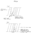
- Fig. 4 schematically shows the relation of the relative positions between the rotary magnetic head and the track in the case of a search slow to normal run transition (one times greater speed).
- the tracking can be accurately effected by setting the deceleration timing by taking into account the amount of deceleration time dependent on speed information and the amount of deceleration time dependent on the deviation from the ideal position.
- the tracking can be likewise accurately effected by setting the start timing by taking into account the amount of start time dependent on speed information and the amount of delay time dependent on the deviation from the ideal position, as shown in Fig. 4 (b).
- the relative position of the track with respect to the magnetic head at the time of tape stoppage can be accurately detected by counting the FG pulses corresponding to the rotation of the capstan motor during the running of the magnetic tape and resetting the count by the CTL signal recorded on the linear track on the magnetic tape.
- the start timing is controlled on the basis of the stop position detected at the time of stoppage of the tape run, whereby the immediate on-track action is possible even immediately after the start, so that a stabilized image can be obtained.
- stabilized high speed pull-in can be achieved in a VTR which operates on the basis of narrow track high density recording.
- detection of the CTL signal on the magnetic head by the fixed magnetic head allows the tape position to be correctly detected even during transients caused by a brake mechanism or the like.
- the tracking can be accurately effected during the transition to the normal run.
- the FG pulses corresponding to the rotation of the capstan motor can be counted at all times, so that the magnetic tape stop timing can be optionally set.
- Fig. 5 is a block diagram showing the arrangement of the magnetic recording and reproducing device according to the second embodiment.
- those parts which function in the same way as in the magnetic recording and reproducing device of the first embodiment are given the same reference characters and a description thereof is omitted.
- the numeral 1 denotes a magnetic tape wherein one frameful of information is divided for 10 oblique tracks and a pilot signal is multi-recorded thereon and CTL signals are recorded thereon in the direction of travel of the tape;
- 10 denotes a tracking control section for detecting a pilot signal contained in a signal to be reproduced from the drum 3 to output a tracking error signal;
- 11 denotes a CTL phase shift detecting section for comparing the CTL signal from the fixed magnetic head 12 with the head switching signal from the head switching pulse generator 5 to detect and store the phase shift of the CTL signal;
- 20 denotes a capstan motor driving section which effects tracking control by selecting the CTL signal from the fixed magnetic head and the tracking error signal from the tracking control section 10 and which, when using the CTL signal to effect tracking control, controls as an error signal the phase shift with respect to the output of the CTL phase shift detecting section 11;
- 60 denotes a timing control section for controlling the timing for starting the running of the magnetic tape 1 on the basis
- Fig. 6 is a time chart showing the phase relation between the reference frame signal, the head switching pulse signal and the CTL signal when the ATF tracking reproduction is effected as the capstan motor driving section 20 selects the tracking error signal from the tracking control section 10.
- the phase of the CTL signal reproduced from the magnetic tape 1 by the fixed magnetic head 12 is deviated from the design phase shown in solid lines owing to changes with time, such as elongation or contraction of the magnetic tape, having a DC offset shown in broken lines.
- the detected position by correcting the detected position by an amount corresponding to the offset, it is possible to prevent the precision of detection from decreasing owing to the phase shift of the CTL signal.
- the magnetic recording and reproducing device according to the second embodiment described above has the following effects in addition to the effects of the magnetic recording and reproducing device according to the first embodiment.
- the detection and storage of the phase shift of the CTL signal during ATF tracking control removes the offset in the CTL signal due to the elongation or contraction of the magnetic tape and enables the detection of the stop position of the tape to be made with precision despite changes with time due to the elongation or contraction of the magnetic tape.
- the detection and storage of the phase shift of the CTL signal during ATF tracking control makes it possible, in the case where clogging takes place in the rotary magnetic head, to achieve precision tracking control by switching to a control mode using the CTL signal.
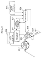
- Fig. 7 is a block diagram showing the arrangement of the magnetic recording and reproducing device according to the third embodiment.
- the magnetic tape 101 is wrapped around a rotary cylinder 102 and driven in the direction of arrow Y3.
- the rotary cylinder 102 has magnetic heads 103R and 103L mounted thereon at symmetrical positions.
- a fixed magnetic head 104 is disposed for reproducing the linear track along the direction of travel of the magnetic tape 101.
- a reference frame signal generator 105 is used to generate the reference frame signal.
- the magnetic tape 101 is driven at a constant speed by a capstan motor 107 which drives the capstan.
- the capstan motor 107 has the FG detector 108 connected thereto, and its output is fed into a compensator 106.
- the tracking error detector 109 is used to detect an error signal from the signal from the reproducing magnetic head 104, while the reproduction frame phase information detector 110 is used to detect the phase information on the reproduction frame, their outputs being fed into a compensator 106.
- the compensator 106 drives the capstan motor 107 on the basis of these signals, as will be later described.
- FIG. 8 An example of a record pattern on the magnetic tape 101 used in this magnetic recording and reproducing device is shown in Fig. 8.
- the characters 121A - 121J denote tracks in which the usual recorded signal and the reproduction frame phase information are recorded, and 122 denotes the CTL track.
- To obtain the reproduced image from this magnetic tape 101 it is necessary to control the tracking such that the magnetic heads correctly land on the tracks and at the same time the phase of the reference frame signal obtained from the reference frame signal generator coincides with the phase of the reproduction frame phase information obtained from the reproduction signal.
- the rotary cylinder 102 rotates at a predetermined rpm, and data is read from the magnetic tape 101 wrapped around the rotary cylinder 102 by the magnetic heads 103R and 103L, so as to output the reproduced signal.
- the magnetic tape 101 is at a stop.
- the predetermined timing is calculated by the compensator 106.
- the capstan motor 107 is started by the capstan control signal. Then the capstan motor 107 is accelerated at a constant rate until it reaches the predetermined speed.
- the compensator 106 controls the feed speed of the magnetic tape 101 by the FG signal obtained from the FG detector 108 so as to cause the capstan motor 107 to attain the predetermined speed.
- the tracking error detector 109 detects a tracking error, effecting the tracking control.
- the reproduction frame phase information detector 110 detects the reproduction frame phase information from the reproduction signal, and the compensator 106 thereby feeds the magnetic tape 101 by an amount corresponding to about M frames.
- the capstan motor 107 is switched to the brake mode for deceleration (M and N being any natural numbers). And the capstan motor 107 is stopped for the time corresponding to about N frames.
- Fig. 9 shows the time chart for the slow operation.
- Fig. 9 (a) shows the travel speed of the magnetic tape;
- Fig. 9 (b) shows the capstan control signal showing accelerating and decelerating instructions to the capstan motor;
- Fig. 9 (c) shows the frame reference signal which shows the demarcation between frames by a binary system using H and L;
- Fig. 9 (d) shows the reproduction frame phase information which shows the demarcation between reproduction frames by the binary system using H and L from the track being reproduced by the magnetic head.
- the value of the frame reference signal is switched from L to H.
- the compensator 106 calculates the time t31 for starting acceleration such that the phase of the frame reference signal coincides with the phase of the reproduction frame phase information at time t32.
- the capstan control signal which shows acceleration at time t31 is outputted, to accelerate the capstan motor 107.
- the capstan motor 107 reaches the predetermined speed, the division of the frame reference signal coincides with the division of the reproduction frame phase information and so do their phases. From here, the magnetic tape 101 is fed M frames by the capstan motor 107.
- the capstan motor 107 is switched to the brake mode and, as shown in Fig. 9 (b), the capstan control signal showing the decelerating signal is outputted to decelerate the capstan motor 107.
- the deceleration instruction is stopped from being given to the capstan motor 107, so as to allow the latter to come to a natural stop (at time t35).
- the start timing for the capstan motor 107 is again calculated at time t36, the same operation being repeated.
- the capstan motor 107 effects intermittent feed corresponding to about M frames and then it is stopped for a predetermined time. Because of the period of this intermittent feed, the speed of the slow operation is defined as M / (M + N) .
- the capstan motor is started with a predetermined timing in synchronism with the frame reference (or field reference) signal and after the magnetic tape has been moved by about M frames, brakes are applied in response to the reproduction frame phase information from the reproduction signal to stop the magnetic tape for a time corresponding to N frames, whereby the M / (M + N) times slower operation can be achieved without requiring a special circuit or complicated software-wise processing.
- a magnetic recording and reproducing device according to a fourth embodiment of the invention will now be described.
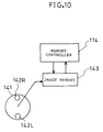
- Fig. 10 is a block diagram of a magnetic head in the fourth embodiment.
- a rotary cylinder 141 has magnetic heads 142R and 142L attached thereto.
- An image memory 143 which is a memory for storing image data is a memory for temporally holding the reproduction signal outputted from the magnetic head, and a memory controller 144 is used to control the image memory 143. The rest of the arrangement is the same as in the first embodiment.
- Fig. 12 is a schematic view showing the arrangement of the image memory 143.
- data for the track 1 is stored successively in the memory addresses AD810, AD811, ..., D81x by the scanning by the magnetic head of the VTR, and then the data for the track 2 is stored, beginning with AD820; in this manner, data for one frame each time is stored until AD8Nx is reached.
- reproduction data is stored in predetermined addresses in the image memory 143 by the memory controller 144.
- the timing for applying brakes to the capstan is determined on the basis of the reproduction data for each frame actually obtained by ascertaining the addresses and data stored in the image memory 143, whereby slow reproduction which is highly reliable with no noises appearing on the screen is made possible.
- a memory for storing the reproduction signal and the brake timing is determined by the address for the image memory, whereby brakes can be applied at the optimum position, and by checking the contents of the memory, a reproduced image with no noise can be reliably obtained and the reliability can be increased.
- a magnetic recording and reproducing device according to a fifth embodiment of the invention will now be described.
- FIG. 11 is a block diagram showing the arrangement of the magnetic recording and reproducing device according to the fifth embodiment.
- a magnetic tape 501, rotary cylinder 502, magnetic heads 503L and 503R, fixed magnetic head 504, reference frame signal generator 505, compensator 506, capstan motor 507, and FG detector 508 are the same as those described in the third embodiment and correspondingly numbered from 101 through 108.
- the ATF tracking error detector 509 detects the level difference produced by the tracking error from the pilot signal recorded in advance on oblique tracks of the magnetic tape.
- the head position detecting circuit 510 is used to detect what position on the magnetic tape the magnetic head scans, by calculating the number of pulses of FG signal obtained during the period of the reproduction CTL signal.
- the numeral 511 denotes a CTL shift detecting circuit for detecting the shift of the reproduction CTL signal from the reference frame signal. The rest of the arrangement is the same as in the third embodiment.
- correct frame synchronization and hence stabilized slow operation can be attained even when there is an error in regard to the position for installing the fixed magnetic head or an error due to changes with time, such as elongation or contraction of the magnetic tape or a phase shift in the CTL signal during interchangeable reproduction.
- a magnetic recording and reproducing device showing a sixth embodiment of the invention will now be described.
- Fig. 13 is a block diagram showing the arrangement of the magnetic recording and reproducing device according to the sixth embodiment.
- magnetic heads 210a and 210b are attached adjacent each other to a rotary drum 201 on the same base with their heights differing by one track from each other;
- 202 denotes a magnetic tape;
- 203 denotes a capstan motor for moving the magnetic tape 202 at a predetermined speed;
- 204 denotes a capstan driving section for driving the capstan motor 203;
- 205 denotes an information signal generating section for generating an information signal to be sent to the magnetic heads 210a and 210b;
- 206 denotes a stop and start control section for controlling the stop and start timing for the capstan motor 203 and the output timing for the information signal, with the timing which is in synchronism with the phase of rotation of the rotary drum 201.
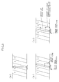
- Fig. 14 (a) schematically shows the track pattern on the magnetic tape.
- the scanning trail of the magnetic head for intermittent recording is shown.
- Fig. 14 (b) shows the speed at which the magnetic tape 202 is fed by the capstan motor 203.
- the mark "x1" indicates the same speed state as in the normal recording and reproducing, and "x0" indicates the stop state.
- the wrapping angle (effective track angle) at this time is supposed to be 180 degrees.
- the magnetic head 210a scans and records the track 0 (1 in the figure) at the ordinary speed, then the magnetic tape is immediately decelerated (2 in the figure) and stopped (3 in the figure).
- the magnetic tape is accelerated in the ineffective region (4 in the figure) and the recording of the track 2 is effected (5 in the figure).
- the magnetic tape is controlled such that it is fed by an amount corresponding to one track.
- ⁇ K ⁇ T / J (where K: proportionality constant, J: moment of inertia, T: motor torque).
- the tape travel distance can be set at the desired value (corresponding to one track) by selecting the above torque for one track scan time during deceleration or acceleration and effecting deceleration or acceleration.
- the odd-numbered tracks are recorded and the operation is the same as in the magnetic head 210a.
- Fig. 15 (a) which shows the head scan trail
- Fig. 15 (a) which shows the head scan trail
- Fig. 16 is a motion explanation chart for intermittent recording at a wrapping angle of not more than 180 degrees, e.g., 150 degrees.
- the magnetic head 210a is in the illustrated position (the same position as in the broken line 210a').
- the distance travelled from this point of time till the time the next track 2 is recorded corresponds, in the track width, to one track.
- the distance of travel is 7 / 6 of the value for a wrapping angle of 180 degrees, as the effective region is shortened by an amount of 30 degrees. Therefore, with the same deceleration or acceleration as in the case of a wrapping angle of 180 degrees, the magnetic tape is moved for more time in the ordinary speed state, the excess time being to / 6 of the time taken for the wrapping angle of 180 degrees.
- Fig. 17 is a motion explanation chart for intermittent recording at a wrapping angle of not more than 180 degrees, e.g., 210 degrees.
- the magnetic head 210a At a point of time of termination of the recording of the track 0, the magnetic head 210a is in the illustrated position (the same position as in the broken line 210a'). The distance travelled from this point of time till the time the next track 2 is recorded corresponds, in the track width, to one track.
- the distance of travel is 5 / 6 of the value for a wrapping angle of 180 degrees, as the effective region is prolonged by an amount of 30 degrees.
- deceleration or acceleration should be increased as compared with the case of a wrapping angle of other than 180 degrees. For example, if the deceleration or acceleration time is set at 5 / 6 of the value for 180 degrees, the absolute value of deceleration or acceleration is set at 6 / 5 of the value for 180 degrees.
- the amount of travel in the direction of feed of the magnetic tape can be easily designed according to the wrapping angle.
- the information signal is recorded on the track by the pair of magnetic heads attached adjacent each other to the rotary drum with their heights differing by one track from each other; therefore, by effecting stoppage and start upon termination of recording and feeding said magnetic tape by an amount corresponding to one track before the next recording is started, stoppage and start can be effected in the ineffective region even during intermittent recording, without causing the bending of a track to be recorded. Therefore, during the reproduction, a stabilized image can be obtained without causing envelope chipping.
- a magnetic recording and reproducing device showing a seventh embodiment of the invention will now be described.
- Fig. 18 is a block diagram showing the arrangement of the magnetic recording and reproducing device according to the seventh embodiment.
- those parts which function in the same way as in the magnetic recording and reproducing device of the sixth embodiment are given the same reference characters and a description thereof is omitted.
- the numeral 208 denotes a fixed magnetic head for reproducing the CTL signal recorded on the linear track of a magnetic tape 208;
- 209 denotes an FG pulse detector for detecting FG pulses magnetized on a capstan motor 203;
- 207 denotes a stop position detecting section for detecting the stop position of the magnetic tape 202 on the basis of the outputs from the fixed magnetic head 208 and FG pulse detector 209;
- 260 denotes a stop and start control section for controlling the stop and start timing for the capstan motor 203 and the output timing for the information signal on the basis of the rotary phase of the rotary drum 201 and the output from the stop position detecting section 207.
- the wrapping angle (effective track angle) is supposed to be 180 degrees.
- Fig. 19 is a motion explanation chart for tape position detection in the seventh embodiment and Fig. 20 is a motion explanation chart in tape feed in the same embodiment.
- the positional precision can be improved by detecting the stop position of the magnetic tape.
- the stopped tape position is detected by detecting and counting the FG pulses of the capstan motor and resetting the same with the timing which is in synchronism with the rotary drum.
- the start timing is delayed by to / 4 and the magnetic tape is started at 4 / 3 times the acceleration for the wrapping angle of 180 degrees in the sixth embodiment.
- precision can be improved by controlling the start timing and acceleration irrespective of the stop position of the magnetic tape.
- the arrangement can be simplified by controlling only the start timing while keeping the acceleration at a constant value.
- the precision of the position of a track to be recorded can be further improved as compared with the sixth embodiment by detecting the tape position by the CTL signal which is phase information on the magnetic tape.
- the recording duration can be prolonged.
- a magnetic recording and reproducing device showing an eighth embodiment of the invention will now be described.
- Fig. 21 is a block diagram showing the arrangement of the magnetic recording and reproducing device according to the eighth embodiment.
- those parts which function in the same way as in the magnetic recording and reproducing devices of the sixth and seventh embodiments are given the same reference characters and a description thereof is omitted.
- magnetic heads 210a and 210b are recording magnetic heads attached adjacent each other to a rotary drum on the same base with their heights differing by one track from each other;
- 220 denotes an erasing magnetic head attached to the rotary drum 211 on the same base as and adjacent the recording magnetic heads 210a and 210b and two tracks ahead;
- 255 denotes an erasing signal generating section for generating an erasing signal sent to the erasing magnetic head 220;
- 265 denotes a stop and start control section for controlling the stop and start timing of the capstan motor and the output timing for information signal and erasing signal on the basis of the rotary phase of the rotary drum 211.
- the magnetic tape is stopped or started in other than the effective region for recording and erasing (other than the shaded areas), and two trackfuls of recording is made by the recording magnetic heads 210a and 210b, and while the erasing head 220, preceding the recording heads, effects two trackfuls of erasing.
- the wrapping angle (effective track angle) at this time is supposed to be 180 degrees.
- the stop position of the magnetic tape is detected by detecting or counting the FG pulses from the capstan motor and resetting them with the timing which is in synchronism with the rotary drum, whereby the positional precision for recording and erasing can be improved.
- the magnetic tape 202 may be controlled such that it is fed by an amount corresponding to two tracks from the time immediate recording by the magnetic head 210a is started till the time the next recording is started.
- the magnetic tape 202 may be controlled such that it is fed by an amount corresponding to two tracks from the time immediate erasing by the erasing magnetic head 220 is started till the time the next erasing is started.
- the invention is also applicable to a VTR for variable rate recording by controlling the stop time. Further, since recording can be immediately started in response to a recording instruction without requiring prerolling, there will be no failure in recording.
Landscapes
- Engineering & Computer Science (AREA)
- Signal Processing (AREA)
- Multimedia (AREA)
- Adjustment Of The Magnetic Head Position Track Following On Tapes (AREA)
- Management Or Editing Of Information On Record Carriers (AREA)
Applications Claiming Priority (9)
| Application Number | Priority Date | Filing Date | Title |
|---|---|---|---|
| JP30183995 | 1995-11-21 | ||
| JP301839/95 | 1995-11-21 | ||
| JP30183995A JP3361672B2 (ja) | 1995-11-21 | 1995-11-21 | 再生装置 |
| JP05834096A JP3359809B2 (ja) | 1996-02-20 | 1996-02-20 | ビデオテープレコーダ |
| JP5834096 | 1996-02-20 | ||
| JP58340/96 | 1996-02-20 | ||
| JP05461096A JP3503329B2 (ja) | 1996-03-12 | 1996-03-12 | 磁気記録装置 |
| JP5461096 | 1996-03-12 | ||
| JP54610/96 | 1996-03-12 |
Publications (2)
| Publication Number | Publication Date |
|---|---|
| EP0776006A2 true EP0776006A2 (de) | 1997-05-28 |
| EP0776006A3 EP0776006A3 (de) | 2001-05-02 |
Family
ID=27295353
Family Applications (1)
| Application Number | Title | Priority Date | Filing Date |
|---|---|---|---|
| EP96118625A Withdrawn EP0776006A3 (de) | 1995-11-21 | 1996-11-20 | Magnetische Aufzeichnungs- und Wiedergabevorrichtung |
Country Status (3)
| Country | Link |
|---|---|
| US (1) | US6424483B1 (de) |
| EP (1) | EP0776006A3 (de) |
| KR (1) | KR100266294B1 (de) |
Cited By (1)
| Publication number | Priority date | Publication date | Assignee | Title |
|---|---|---|---|---|
| EP1435612A4 (de) * | 2001-09-27 | 2009-01-07 | Panasonic Corp | Magnetische aufzeichnungs-bzw. wiedergabevorrichtung |
Families Citing this family (4)
| Publication number | Priority date | Publication date | Assignee | Title |
|---|---|---|---|---|
| KR100433198B1 (ko) * | 1998-12-18 | 2004-09-13 | 주식회사 대우일렉트로닉스 | 타임랩스브이씨알의녹화방법 |
| DE19963189A1 (de) * | 1999-12-27 | 2001-06-28 | Thomson Brandt Gmbh | Suchlauf für einen D-VHS Recorder |
| JP4081811B2 (ja) * | 2002-09-10 | 2008-04-30 | ソニー株式会社 | 記録/再生装置および方法、記録媒体、並びにプログラム |
| JP6248727B2 (ja) * | 2014-03-18 | 2017-12-20 | 富士通株式会社 | 磁気テープ制御装置、制御プログラム、及び制御方法 |
Citations (2)
| Publication number | Priority date | Publication date | Assignee | Title |
|---|---|---|---|---|
| JPS59127255A (ja) | 1983-01-11 | 1984-07-23 | Mitsubishi Electric Corp | 間欠記録による長時間磁気録画装置 |
| JPH07192357A (ja) | 1993-12-27 | 1995-07-28 | Sony Corp | コントロール信号の位相サーボ回路 |
Family Cites Families (25)
| Publication number | Priority date | Publication date | Assignee | Title |
|---|---|---|---|---|
| US4044389A (en) * | 1976-03-19 | 1977-08-23 | Ampex Corporation | Method and apparatus for measuring the speed at which a tape was recorded |
| DE2841106B1 (de) * | 1978-09-21 | 1979-11-29 | Siemens Ag | Verfahren und Schaltungsanordnung zum Verkuerzen der Informationsblockluecken des Magnetbandes bzw. zum Verringern der Belastung des Antriebssystems in Magnetbandgeraeten |
| JPS5720073A (en) * | 1980-07-09 | 1982-02-02 | Matsushita Electric Ind Co Ltd | Tracking device |
| JPS57121380A (en) * | 1981-01-22 | 1982-07-28 | Sony Corp | Editing device |
| US4780774A (en) * | 1983-09-22 | 1988-10-25 | Canon Kabushiki Kaisha | Rotary head type reproducing apparatus having a head shifter for accurately shifting the rotary head |
| US4811130A (en) * | 1984-07-02 | 1989-03-07 | Canon Kabushiki Kaisha | Information signal reproducing apparatus capable of determining a track pitch of a record bearing medium using a tracking error signal and a signal indicative of the moving speed of the medium |
| US4692819A (en) | 1984-08-31 | 1987-09-08 | Ampex Corporation | Method and apparatus for controlling the position of a transported web |
| US4731679A (en) * | 1984-09-20 | 1988-03-15 | Ampex Corporation | Method and apparatus for transporting a recording medium with an adaptive velocity change profile |
| US4999722A (en) * | 1984-12-17 | 1991-03-12 | Canon Kabushiki Kaisha | Multi-channel information signal reproducing apparatus for reproducing information signals from a tape-shaped record bearing medium having a plurality of areas which respectively extend longitudinally and parallel with each other |
| JPH0642731B2 (ja) * | 1984-12-27 | 1994-06-01 | 株式会社東芝 | ビデオテ−プレコ−ダの高速再生装置 |
| CA1270946A (en) | 1985-07-23 | 1990-06-26 | Mitsugu Yoshihiro | Capstan servo circuit |
| US4882634A (en) * | 1986-03-18 | 1989-11-21 | Canon Kabushiki Kaisha | Apparatus for reproducing information signals by intermittently feeding tape-shaped record bearing medium |
| JPH0229983A (ja) * | 1988-07-18 | 1990-01-31 | Canon Inc | 磁気記録再生装置 |
| JP2587475B2 (ja) * | 1988-10-21 | 1997-03-05 | 株式会社日立製作所 | デジタル磁気記録再生装置 |
| US5088077A (en) | 1988-11-10 | 1992-02-11 | Ampex Corporation | Synchronization of record media transports and tracking adjustment |
| JPH0489657A (ja) * | 1990-07-25 | 1992-03-23 | Mitsubishi Electric Corp | コントロールトラック信号出力装置 |
| JPH04247381A (ja) * | 1991-01-31 | 1992-09-03 | Sony Corp | データ再生装置 |
| US5339200A (en) * | 1991-03-01 | 1994-08-16 | Canon Kabushiki Kaisha | Signal recording apparatus with rerecording facility |
| JPH052799A (ja) | 1991-06-25 | 1993-01-08 | Canon Inc | 回転ヘツド型記録又は再生装置 |
| JPH05284463A (ja) * | 1992-03-30 | 1993-10-29 | Sony Corp | ディジタルvtrの音声データ再生装置 |
| JP2806135B2 (ja) | 1992-04-03 | 1998-09-30 | 松下電器産業株式会社 | 再生装置 |
| KR940009869B1 (ko) * | 1992-06-26 | 1994-10-18 | 주식회사금성사 | Vcr 서어보오계에서의 속도/위상 안정화 장치와 안정화 제어방법 |
| US5825971A (en) | 1992-07-30 | 1998-10-20 | Mitsubishi Denki Kabushiki Kaisha | Magnetic head replacement structure in helical scan magnetic recording and reproducing apparatus and method thereof |
| JP3023580B2 (ja) | 1992-07-30 | 2000-03-21 | 三菱電機株式会社 | 磁気記録装置 |
| JPH06131756A (ja) * | 1992-10-15 | 1994-05-13 | Hitachi Ltd | データ記録再生装置 |
-
1996
- 1996-11-18 US US08/751,480 patent/US6424483B1/en not_active Expired - Fee Related
- 1996-11-20 EP EP96118625A patent/EP0776006A3/de not_active Withdrawn
- 1996-11-20 KR KR1019960055783A patent/KR100266294B1/ko not_active Expired - Fee Related
Patent Citations (2)
| Publication number | Priority date | Publication date | Assignee | Title |
|---|---|---|---|---|
| JPS59127255A (ja) | 1983-01-11 | 1984-07-23 | Mitsubishi Electric Corp | 間欠記録による長時間磁気録画装置 |
| JPH07192357A (ja) | 1993-12-27 | 1995-07-28 | Sony Corp | コントロール信号の位相サーボ回路 |
Non-Patent Citations (1)
| Title |
|---|
| BROADCASTING TECHNIQUE., vol. 43, no. 12, 1990 |
Cited By (1)
| Publication number | Priority date | Publication date | Assignee | Title |
|---|---|---|---|---|
| EP1435612A4 (de) * | 2001-09-27 | 2009-01-07 | Panasonic Corp | Magnetische aufzeichnungs-bzw. wiedergabevorrichtung |
Also Published As
| Publication number | Publication date |
|---|---|
| KR970067205A (ko) | 1997-10-13 |
| KR100266294B1 (ko) | 2000-09-15 |
| US6424483B1 (en) | 2002-07-23 |
| EP0776006A3 (de) | 2001-05-02 |
Similar Documents
| Publication | Publication Date | Title |
|---|---|---|
| US4394694A (en) | Tape synchronizing apparatus | |
| US4536806A (en) | Microprocessor controlled multiple servo system for a recording and/or reproducing apparatus | |
| GB1208356A (en) | Magnetic recording and playback system | |
| US4396954A (en) | Still mode video signal reproducing apparatus | |
| US4283744A (en) | Video reproducing apparatus with variable delay means | |
| US6424483B1 (en) | Control system of tape travel for a magnetic recording and reproducing apparatus | |
| GB1294264A (en) | Automatic phasing of servo systems used in tape transport systems | |
| US4672474A (en) | Synthetic control track signal producing apparatus for video tape machines | |
| EP0587320B1 (de) | Signalwiedergabegerät | |
| JP2798091B2 (ja) | ビデオテープレコーダをキュー操作するための装置及び方法 | |
| US4086520A (en) | Speed and phase control system | |
| EP0249382B1 (de) | Gerät zur Wiedergabe von Videosignalen als Zeitlupenaufnahme | |
| EP0200203B1 (de) | Vorrichtung für die langsame Bewegung des Bandes einer magnetischen Aufzeichnungs- und Wiedergabeanordnung | |
| US4751586A (en) | Rotary head tape transport servo system having high speed servo lock capability | |
| JP3423194B2 (ja) | 磁気記録装置 | |
| JPH0197076A (ja) | フレームインデツクス磁気記録再生装置 | |
| EP0104023B1 (de) | Gerät und Verfahren für Videobandmaschinen welches ein synthetisches Steuerungsspursignal erzeugt | |
| KR0147554B1 (ko) | 비데오 테이프 레코더의 트랙킹 제어방법 | |
| JP3361672B2 (ja) | 再生装置 | |
| JP3359809B2 (ja) | ビデオテープレコーダ | |
| EP0311143A2 (de) | Verfahren und Vorrichtung zum Erzeugen eines künstlichen Synchronisiersignals | |
| US5194961A (en) | Apparatus for locking a reproduced color video signal to a reference color frame signal | |
| JP3503329B2 (ja) | 磁気記録装置 | |
| US4633341A (en) | Tape address adjusting apparatus for video tape recorder | |
| JP3363572B2 (ja) | 磁気記録再生装置 |
Legal Events
| Date | Code | Title | Description |
|---|---|---|---|
| PUAI | Public reference made under article 153(3) epc to a published international application that has entered the european phase |
Free format text: ORIGINAL CODE: 0009012 |
|
| AK | Designated contracting states |
Kind code of ref document: A2 Designated state(s): DE FR GB NL |
|
| RIC1 | Information provided on ipc code assigned before grant |
Free format text: 7G 11B 15/18 A, 7G 11B 15/467 B, 7G 11B 15/087 B, 7G 11B 15/12 B, 7G 11B 15/52 B, 7G 11B 27/032 B, 7G 11B 27/13 B, 7G 11B 27/32 B |
|
| PUAL | Search report despatched |
Free format text: ORIGINAL CODE: 0009013 |
|
| AK | Designated contracting states |
Kind code of ref document: A3 Designated state(s): DE FR GB NL |
|
| 17P | Request for examination filed |
Effective date: 20010516 |
|
| STAA | Information on the status of an ep patent application or granted ep patent |
Free format text: STATUS: THE APPLICATION IS DEEMED TO BE WITHDRAWN |
|
| RAP1 | Party data changed (applicant data changed or rights of an application transferred) |
Owner name: PANASONIC CORPORATION |
|
| 18D | Application deemed to be withdrawn |
Effective date: 20080531 |