EP0776019A2 - Commutateur rotatif - Google Patents
Commutateur rotatif Download PDFInfo
- Publication number
- EP0776019A2 EP0776019A2 EP96118670A EP96118670A EP0776019A2 EP 0776019 A2 EP0776019 A2 EP 0776019A2 EP 96118670 A EP96118670 A EP 96118670A EP 96118670 A EP96118670 A EP 96118670A EP 0776019 A2 EP0776019 A2 EP 0776019A2
- Authority
- EP
- European Patent Office
- Prior art keywords
- housing
- switch according
- base board
- fixing
- switch
- Prior art date
- Legal status (The legal status is an assumption and is not a legal conclusion. Google has not performed a legal analysis and makes no representation as to the accuracy of the status listed.)
- Withdrawn
Links
- 210000002105 tongue Anatomy 0.000 claims abstract description 14
- 239000011810 insulating material Substances 0.000 claims abstract description 4
- 239000002184 metal Substances 0.000 claims description 17
- 238000005304 joining Methods 0.000 claims description 8
- 238000003475 lamination Methods 0.000 claims description 7
- 238000000034 method Methods 0.000 claims description 4
- 239000000463 material Substances 0.000 claims description 3
- 230000000087 stabilizing effect Effects 0.000 claims description 3
- 230000013011 mating Effects 0.000 claims description 2
- 238000003486 chemical etching Methods 0.000 abstract 1
- 238000001465 metallisation Methods 0.000 abstract 1
- 238000005253 cladding Methods 0.000 description 10
- 238000004519 manufacturing process Methods 0.000 description 4
- 238000005530 etching Methods 0.000 description 2
- 239000000126 substance Substances 0.000 description 2
- 230000004308 accommodation Effects 0.000 description 1
- 239000000853 adhesive Substances 0.000 description 1
- 230000001070 adhesive effect Effects 0.000 description 1
- 230000015572 biosynthetic process Effects 0.000 description 1
- 230000001419 dependent effect Effects 0.000 description 1
- 230000007257 malfunction Effects 0.000 description 1
- 230000035515 penetration Effects 0.000 description 1
- 238000010079 rubber tapping Methods 0.000 description 1
- 238000007790 scraping Methods 0.000 description 1
- 229910000679 solder Inorganic materials 0.000 description 1
Images

Classifications
-
- H—ELECTRICITY
- H01—ELECTRIC ELEMENTS
- H01H—ELECTRIC SWITCHES; RELAYS; SELECTORS; EMERGENCY PROTECTIVE DEVICES
- H01H19/00—Switches operated by an operating part which is rotatable about a longitudinal axis thereof and which is acted upon directly by a solid body external to the switch, e.g. by a hand
- H01H19/02—Details
- H01H19/10—Movable parts; Contacts mounted thereon
- H01H19/11—Movable parts; Contacts mounted thereon with indexing means
- H01H19/115—Movable parts; Contacts mounted thereon with indexing means using molded elastic parts only
-
- H—ELECTRICITY
- H01—ELECTRIC ELEMENTS
- H01H—ELECTRIC SWITCHES; RELAYS; SELECTORS; EMERGENCY PROTECTIVE DEVICES
- H01H1/00—Contacts
- H01H1/58—Electric connections to or between contacts; Terminals
- H01H1/5805—Connections to printed circuits
-
- H—ELECTRICITY
- H01—ELECTRIC ELEMENTS
- H01H—ELECTRIC SWITCHES; RELAYS; SELECTORS; EMERGENCY PROTECTIVE DEVICES
- H01H19/00—Switches operated by an operating part which is rotatable about a longitudinal axis thereof and which is acted upon directly by a solid body external to the switch, e.g. by a hand
- H01H19/02—Details
- H01H19/04—Cases; Covers
-
- H—ELECTRICITY
- H01—ELECTRIC ELEMENTS
- H01H—ELECTRIC SWITCHES; RELAYS; SELECTORS; EMERGENCY PROTECTIVE DEVICES
- H01H19/00—Switches operated by an operating part which is rotatable about a longitudinal axis thereof and which is acted upon directly by a solid body external to the switch, e.g. by a hand
- H01H19/54—Switches operated by an operating part which is rotatable about a longitudinal axis thereof and which is acted upon directly by a solid body external to the switch, e.g. by a hand the operating part having at least five or an unspecified number of operative positions
- H01H19/56—Angularly-movable actuating part carrying contacts, e.g. drum switch
- H01H19/58—Angularly-movable actuating part carrying contacts, e.g. drum switch having only axial contact pressure, e.g. disc switch, wafer switch
- H01H19/585—Angularly-movable actuating part carrying contacts, e.g. drum switch having only axial contact pressure, e.g. disc switch, wafer switch provided with printed circuit contacts
Definitions
- the invention relates to a rotary switch with the features of the preamble of claim 1.
- the housing projections penetrate the base plate in the holes assigned to them and engage behind them with a hook-like undercut that is effective radially to the direction of penetration.
- the distance of the hook-like undercut from the front of the housing is constant.
- the invention is therefore based on the object of designing a rotary switch of the type mentioned at the outset in such a way that these disadvantages are avoided.
- the solution is the subject of claim 1. This solution corresponds in particular to the fact that the manufacturer supplies the rotary switch to its customer, and possibly also the assembler, in a form not yet connected to the base board.
- the base board is not assembled by the manufacturer of the rotary switch, but only by the customer with the core part consisting of housing, switching wheel and contact spring tongues to form a functional overall switch.
- the distance between the contacts of the switch and the counter contacts of the base board, which are usually etched out of the metal cladding, corresponds with high accuracy in the subject matter of the invention the required distance of the switch contacts from the housing stop.
- the tolerance-dependent varying thickness of the base board and its metal cladding thus have no influence on this important distance. A permanent tapping between the switch housing and the base board is ensured, in the position as predetermined by the abovementioned stop during the assembly process.
- the teaching according to claim 2 ensures that the sensitive spring tongues of the switch-side contact spring are protected to a certain extent by the housing walls of the base switch, the end edges or end faces of the base board forming the abovementioned stop. In this respect, they are protected from the start without additional measures until they are assembled with the base board.
- a preferred embodiment relates to the structure of the coding switch used for the design according to the invention.
- a switch structure is used here in which there is no relative rotary movement directly between the contacts and the counter contacts, but rather a digital pressure contact based on the axial deflection of the spring tongues. This considerably simplifies the formation of the counter-contacts formed by chemical treatment (etching) of the metal cladding of the base board.
- These counter contacts are, in a manner known per se from DE 39 22 710 A1, only point contacts and not complicated wiper tracks as are required as counter contacts in the case of direct rotary contact. As a result, the contact pressure can also be selected as desired without affecting the functionality of the switch.
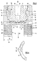
- the core switch or residual switch to be connected to the base board 6 to form the overall switch has the following structure (FIG. 4): It essentially consists of the housing 1 with the housing base 2 which is open to enable contacting with respect to the base board 2. Outer edge 3 forms the stop described below, essential for the precise spacing positioning of the core switch or its housing 1 relative to the base board. Fixing pins 4 protrude beyond the outer surface of the base, that is to say beyond its outer edge 3. A total of four fixing pins 4 are provided in the corner areas of the housing base 2. They correspond to corresponding fixing bores 5 of the base plate 6, the surface of which, in the joined state, faces the housing 1 or the base switch and bears the metal cladding 7.
- the fixed contacts 8 are formed out of this metal cladding 7 by chemical means, for example by etching.
- the base board 6 is made in a manner known per se from insulating material, while the metal lamination is electrically conductive. In the joining state between the housing 1 containing the core switch and the base board 6 with the fixed contacts 8, the overall switch is completed in a functional manner.
- the dividing wheel 9 is mounted rotatably about the axis 10 within the housing 1.
- the central axis of rotation 10 runs parallel to the pin axes 11 and perpendicular to the housing faces 30, 31.
- the switching wheel 9 can be rotated about the axis 10 from the operating side 12 of the switch, for example by a screwdriver or by a handle (not shown) which can be inserted into the wheel opening 13.
- the locking recesses 15 are evenly distributed over the inner circumference 17 (FIG. 2). In the case of an eight-pole rotary coding switch, eight such recesses 15 are accordingly distributed uniformly over the inner circumference 17 of the housing side walls 16. They define the eight rotary positions of the switching wheel 9 or contact positions of the switch.
- the end face 18 of the switching wheel 9 facing the base plate 6 is designed as a cam disk. This means that the end face 18 or its end face contains the coding in the form of protrusions (not shown) projecting in the axial direction 10 towards the base plate 6.
- these shaped projections act on different contact spring tongues 19 of the contact spring 20 fixed in position within the housing 1 and stabilized by an attached stabilizing disc 29 deflected in the axial direction 10, namely in the direction of arrow 21 towards the base plate 6 in such a way that their contact-end fixed contacts 8 act on and contact the base plate 6 in a manner predetermined by the rotary position of the switching wheel 9.
- the fixing pins 4 are inserted into the fixing holes 5 of the base plate 6 corresponding to them. It is introduced in the direction of the arrow 21 into a position in which the housing 1, with its end face 31 or, in short, an outer edge 3 of the housing base, strikes the flat surface 22 of the metal cladding 7 of the base board 6 and bears against it. Exactly in this joining end position, the fixing pins 4 immovably fix the housing 1 to the base board 6.
- the fixing pins 4 are designed in the manner of plug-in plugs. They provide the immovable locking device in the stop position.
- This immovability in the plug-in position is brought about, for example, by a suitable profiling of the circumference of the fixing pins 4, which expediently consist of a plastic material in one piece with the housing 1.
- This plastic material can expediently have a certain basic elasticity.
- This profiling of the surface of the fixing pins can consist, for example, of axial ribs extending in the direction of arrow 21 and projecting beyond the jacket of the fixing pins 4.
- a particularly effective profiling which ensures immovability in the plug-in position or in the stop position is shown in FIG. 5. This is a type of external thread ribbing. To do this, however, it is not necessary for there to be a thread running continuously from the pin base 23 to the pin head 24.
- the fixing projections 28 of the fixing pins 4 are the radially outer tips of ring ribs 25 lined up in the arrow direction 21 and inclined relative to the pin axes 11 with a rib profile corresponding approximately to the profile of a thread.
- the outer diameter 26 of the annular ribs 25 of the fixing pins 4 has such an oversize compared to the inner diameter 27 of the fixing holes 5 (FIG. 3) that, under a certain joining pressure effective in the direction of the arrow 21, the pins 4 are inserted or inserted into the fixing holes 5 is possible, but a secure fit of the fixing pins 4, which is secured against a release movement, is ensured in the stop position of the housing 1 on the base plate 6.
- the annular ribs 25 are contoured in their circumferential area in such a way that on the one hand they allow a slight scraping, on the other hand a partly elastic, but essentially also a plastic deformation. Only the end goal should be ensured that in the stop position there is an immovable positioning of the housing 1 with respect to the base board 6. In principle, it would also be any other type of connection, e.g. a screw connection or a cohesive adhesive connection is conceivable, but this would cause avoidable manufacturing problems.
- the switch is functionally completed by pushing on and joining the housing 1 in the target end position or stop position on the laminated side of the base board 6.
- the subject of the invention advantageously enables the housing 1 with its functional parts shown in FIG. 5 to be manufactured by the specialist set up for such manufacture, while the manufacture of the base plate 6 with the metal lamination 7 and its fixed contacts 8 including the introduction of the bores 5 - the latter expediently as through holes - can be done easily by the assembler or by the circuit builder.
- the assembler can, for example, solder the other electrical components to the base board at higher temperatures, which simplify production, because there is no need to take the residual switch into account, since this is only added as the last part. Because the addition is possible by simply plugging it in, relatively small gaps on the base board 6 are sufficient for the subsequent accommodation of the housing or of housings 1.
- the configuration according to the invention ensures that at the end of the joining process, namely in the stop position of the housing 1 on the base board 6, the movable functional parts of the base switch, essentially its contact spring 20 with the contact spring tongues 19 in exactly their desired position with respect to the fixed contacts 8 of the base board 6 are located.
- This target position in particular the essential contact distance, is predetermined and determined by the outer edge 3 of the housing base 2.
- This outer edge 3 or the stop is generally formed by the flat housing end face 31, which is on the equally flat surface 22 of the metal lamination 7 of the base board 6 strikes and is permanently fixed to the base board 6 in this impact or stop position.
Landscapes
- Physics & Mathematics (AREA)
- Electromagnetism (AREA)
- Rotary Switch, Piano Key Switch, And Lever Switch (AREA)
Applications Claiming Priority (2)
| Application Number | Priority Date | Filing Date | Title |
|---|---|---|---|
| DE1995143980 DE19543980A1 (de) | 1995-11-25 | 1995-11-25 | Codierschalter zur Bestückung einer Basisplatine |
| DE19543980 | 1995-11-25 |
Publications (2)
| Publication Number | Publication Date |
|---|---|
| EP0776019A2 true EP0776019A2 (fr) | 1997-05-28 |
| EP0776019A3 EP0776019A3 (fr) | 1998-08-26 |
Family
ID=7778412
Family Applications (1)
| Application Number | Title | Priority Date | Filing Date |
|---|---|---|---|
| EP96118670A Withdrawn EP0776019A3 (fr) | 1995-11-25 | 1996-11-21 | Commutateur rotatif |
Country Status (2)
| Country | Link |
|---|---|
| EP (1) | EP0776019A3 (fr) |
| DE (1) | DE19543980A1 (fr) |
Cited By (1)
| Publication number | Priority date | Publication date | Assignee | Title |
|---|---|---|---|---|
| CN113471007A (zh) * | 2021-06-24 | 2021-10-01 | 广州本立工业开关制造有限公司 | 一种快捷型多刀开关 |
Citations (4)
| Publication number | Priority date | Publication date | Assignee | Title |
|---|---|---|---|---|
| EP0098532A1 (fr) | 1982-07-09 | 1984-01-18 | International Standard Electric Corporation | Commutateur rotatif pour fixage à une plaque de circuit imprimé |
| JPS59149340A (ja) | 1983-02-15 | 1984-08-27 | Matsushita Electric Ind Co Ltd | 複写機の原稿台冷却装置 |
| JPS59149339A (ja) | 1983-02-16 | 1984-08-27 | Matsushita Electric Ind Co Ltd | 原稿照明装置 |
| DE3922710A1 (de) | 1988-08-11 | 1990-02-15 | Copal Electronics | Drehschalter |
Family Cites Families (9)
| Publication number | Priority date | Publication date | Assignee | Title |
|---|---|---|---|---|
| DE1936563U (de) * | 1965-08-16 | 1966-04-14 | Siemens Ag | Traegerplatte zur aufnahme von steckbaren bauelementen. |
| US3934104A (en) * | 1974-09-23 | 1976-01-20 | Stout Glenn M | Push-button switch |
| DE2504717C3 (de) * | 1975-02-05 | 1979-09-13 | Knab, Heinz, 7022 Leinfelden | Miniaturdrehschalter in Kompaktbauweise |
| DE2927547A1 (de) * | 1979-07-07 | 1981-01-15 | Hartmann & Braun Ag | Messtellenumschalter |
| US4625084A (en) * | 1984-11-29 | 1986-11-25 | Robertshaw Controls Company | Rotary switch construction and method of making the same |
| DE3641427A1 (de) * | 1986-12-04 | 1988-06-09 | Hengstler Bauelemente | Relais mit adapterplatte fuer die platinemontage |
| DE8804603U1 (de) * | 1988-04-07 | 1988-05-19 | Robert Seuffer GmbH & Co, 7260 Calw | Einstelleinrichtung mit mehreren an einer Montageplatte angeordneten Kodierschaltern |
| DE9015967U1 (de) * | 1989-12-23 | 1991-02-14 | Hofsäss, Peter, 75181 Pforzheim | Temperaturschalter mit Bimetall-Schaltwerk |
| IT1251257B (it) * | 1991-12-23 | 1995-05-05 | Vimercati Spa | Commutatore elettrico. |
-
1995
- 1995-11-25 DE DE1995143980 patent/DE19543980A1/de not_active Ceased
-
1996
- 1996-11-21 EP EP96118670A patent/EP0776019A3/fr not_active Withdrawn
Patent Citations (4)
| Publication number | Priority date | Publication date | Assignee | Title |
|---|---|---|---|---|
| EP0098532A1 (fr) | 1982-07-09 | 1984-01-18 | International Standard Electric Corporation | Commutateur rotatif pour fixage à une plaque de circuit imprimé |
| JPS59149340A (ja) | 1983-02-15 | 1984-08-27 | Matsushita Electric Ind Co Ltd | 複写機の原稿台冷却装置 |
| JPS59149339A (ja) | 1983-02-16 | 1984-08-27 | Matsushita Electric Ind Co Ltd | 原稿照明装置 |
| DE3922710A1 (de) | 1988-08-11 | 1990-02-15 | Copal Electronics | Drehschalter |
Cited By (1)
| Publication number | Priority date | Publication date | Assignee | Title |
|---|---|---|---|---|
| CN113471007A (zh) * | 2021-06-24 | 2021-10-01 | 广州本立工业开关制造有限公司 | 一种快捷型多刀开关 |
Also Published As
| Publication number | Publication date |
|---|---|
| DE19543980A1 (de) | 1997-05-28 |
| EP0776019A3 (fr) | 1998-08-26 |
Similar Documents
| Publication | Publication Date | Title |
|---|---|---|
| DE4419055C2 (de) | Chip-Schmelzsicherung | |
| DE2409662A1 (de) | Elektrische verbinderanordnung | |
| DE1665757B2 (de) | Steckverbinder fuer gedruckte schaltungen | |
| DE2617186A1 (de) | Elektrischer schalter | |
| EP0024363B1 (fr) | Lampe électrique avec un culot sous forme de douille | |
| DE102019104558B4 (de) | Steckverbinderteil mit einer Rasteinrichtung | |
| DE2719194A1 (de) | Befestigungsvorrichtung fuer einen schalter | |
| EP0600153B1 (fr) | Douille de contact | |
| DE4101316C1 (fr) | ||
| EP0776019A2 (fr) | Commutateur rotatif | |
| DE4407083C2 (de) | Steckverbindergehäuse und zugehöriger Steckverbinder | |
| EP0123040B1 (fr) | Plaque à bornes pour des appareils électriques ou électroniques, par exemple pour un interrupteur de protection contre la surintensité | |
| DE2641340C3 (de) | Drehverbindung als Teil eines Türklinken-Betätigungsmechanismus und einer hierin drehbar angeordneten Metallstange | |
| EP0093236B1 (fr) | Fiche pour appareil | |
| DE3202241C2 (fr) | ||
| DE4129983C2 (de) | Verbindungsanordnung zwischen einem mit einer Kontaktbuchse versehenen Anzeigegerät und einer flexiblen Leiterplatte | |
| EP0024773A1 (fr) | Boîtier pour une prise électrique | |
| DE3324255C2 (fr) | ||
| DE2826886A1 (de) | Mehrfach-stufendrehschalter | |
| DE2502957C3 (de) | Stufendrehschalter für Vielfach-Meßinstrumente | |
| DE2654502C2 (de) | Kontaktanordnung an Isolierstoffteilen elektrischer Bauelemente | |
| DE7919534U1 (de) | Drehschalter | |
| DE3340654A1 (de) | Loesbare rasteinrichtung fuer insbesondere mehrpolige elektrische steckverbindungen | |
| EP1277256B1 (fr) | Dispositif permettant de fixer de maniere amovible une plaque avant sur une barre de support d'un boitier | |
| DE102017105470B4 (de) | Leuchtenbaugruppe |
Legal Events
| Date | Code | Title | Description |
|---|---|---|---|
| PUAI | Public reference made under article 153(3) epc to a published international application that has entered the european phase |
Free format text: ORIGINAL CODE: 0009012 |
|
| AK | Designated contracting states |
Kind code of ref document: A2 Designated state(s): CH DE FR GB IT LI |
|
| PUAL | Search report despatched |
Free format text: ORIGINAL CODE: 0009013 |
|
| AK | Designated contracting states |
Kind code of ref document: A3 Designated state(s): CH DE FR GB IT LI |
|
| STAA | Information on the status of an ep patent application or granted ep patent |
Free format text: STATUS: THE APPLICATION IS DEEMED TO BE WITHDRAWN |
|
| 18D | Application deemed to be withdrawn |
Effective date: 19990227 |