EP0776101A2 - Procédé et dispositif de transmission bidirectionnel pour signaux numériques à haut débit utilisant une diversité d'espace - Google Patents
Procédé et dispositif de transmission bidirectionnel pour signaux numériques à haut débit utilisant une diversité d'espace Download PDFInfo
- Publication number
- EP0776101A2 EP0776101A2 EP96107315A EP96107315A EP0776101A2 EP 0776101 A2 EP0776101 A2 EP 0776101A2 EP 96107315 A EP96107315 A EP 96107315A EP 96107315 A EP96107315 A EP 96107315A EP 0776101 A2 EP0776101 A2 EP 0776101A2
- Authority
- EP
- European Patent Office
- Prior art keywords
- signal
- base station
- radio channel
- diversity
- transfer function
- Prior art date
- Legal status (The legal status is an assumption and is not a legal conclusion. Google has not performed a legal analysis and makes no representation as to the accuracy of the status listed.)
- Withdrawn
Links
Images


Classifications
-
- H—ELECTRICITY
- H04—ELECTRIC COMMUNICATION TECHNIQUE
- H04B—TRANSMISSION
- H04B7/00—Radio transmission systems, i.e. using radiation field
- H04B7/02—Diversity systems; Multi-antenna system, i.e. transmission or reception using multiple antennas
- H04B7/04—Diversity systems; Multi-antenna system, i.e. transmission or reception using multiple antennas using two or more spaced independent antennas
- H04B7/06—Diversity systems; Multi-antenna system, i.e. transmission or reception using multiple antennas using two or more spaced independent antennas at the transmitting station
- H04B7/0613—Diversity systems; Multi-antenna system, i.e. transmission or reception using multiple antennas using two or more spaced independent antennas at the transmitting station using simultaneous transmission
-
- H—ELECTRICITY
- H04—ELECTRIC COMMUNICATION TECHNIQUE
- H04B—TRANSMISSION
- H04B7/00—Radio transmission systems, i.e. using radiation field
- H04B7/02—Diversity systems; Multi-antenna system, i.e. transmission or reception using multiple antennas
- H04B7/04—Diversity systems; Multi-antenna system, i.e. transmission or reception using multiple antennas using two or more spaced independent antennas
- H04B7/08—Diversity systems; Multi-antenna system, i.e. transmission or reception using multiple antennas using two or more spaced independent antennas at the receiving station
- H04B7/0837—Diversity systems; Multi-antenna system, i.e. transmission or reception using multiple antennas using two or more spaced independent antennas at the receiving station using pre-detection combining
- H04B7/0842—Weighted combining
- H04B7/0845—Weighted combining per branch equalization, e.g. by an FIR-filter or RAKE receiver per antenna branch
Definitions
- the invention relates to a method for the bidirectional transmission of high-rate digital signals between at least one base station and at least one customer device via a radio link according to claim 1, a base station described in claim 9 for a digital radio network for carrying out the method and a digital radio network defined in claim 20 for execution of the procedure.
- the difficulty lies in finding transmission methods and transmission systems that can minimize the impairment of the digital signal transmission caused by the properties of the radio channel with the least possible effort and at the same time achieve a high bandwidth efficiency.
- the previously known methods for transmitting digital signals at high data rates can basically be divided into single-carrier methods and multi-carrier methods.
- the data stream is modulated onto a high-frequency carrier using a suitable modulation method, such as, for example, the Gaussian Minimum Shift Keying method, coded and transmitted in a suitable manner.
- a suitable modulation method such as, for example, the Gaussian Minimum Shift Keying method
- the signals emitted by a transmitting station are reflected on numerous objects located in the radio field and therefore spread over several radio paths to the receiving station.
- intersymbol interference occurs at the same time, which must be compensated for in the receiver by equalizing the signal.
- Viterbi equalizers based on the maximum likelihood sequence estimation approach are used, for example, or equalizers with a quantized feedback.
- digital signals with high data rates have correspondingly short symbol durations, which can result in inter-symbol interference over a large number of symbols, which cannot be eliminated with conventional Viterbi equalizers or equalizers with quantized feedback.
- the development of powerful time-domain equalizers that could solve this task is currently failing due to excessive hardware requirements.
- frequency domain equalizers require higher circuit complexity in the receivers of both the base station and the customer facilities, since each receiver must perform a transformation in the frequency domain and, after equalization in the frequency domain, must transform back into the time domain. This is particularly disadvantageous from the point of view that the customer facilities should be as simple and inexpensive as possible.
- the invention is therefore based on the object of providing a method for the bidirectional transmission of high-rate digital signals via a radio link, a base station for a digital radio network for carrying out the method and a digital radio network, which use the advantages of the known methods and at the same time reduce or even completely avoid their disadvantages.
- the solution according to the invention consists in particular in that a single-carrier method is used and the radio-specific signal processing is carried out in the receiver of a base station in the frequency domain.
- the digital signal emitted by a stationary or mobile customer device and propagating over several radio channels due to reflections from objects is received at at least two spatially separated diversity antennas of a receiving device of the base station. This reception is also known as diversity reception.
- Each diversity antenna is part of a separate diversity branch.
- the received signal of each diversity branch is converted to the baseband. Then it is transformed into the frequency domain and then subjected to a diversity combination.
- the diversity combination can be carried out on the basis of the known maximum ratio combining (MRC) approach or on the basis of a selection combining approach.
- MRC maximum ratio combining
- the combined signal is then equalized in the frequency domain and finally transformed back into the time domain.
- the digital signal transformed back into the time domain is fed to a demodulator known per se, which recovers the useful data from the complex baseband signal. Thanks to the joint implementation of a diversity combination and an equalization of the combined signal in the frequency domain, a significantly better bit error behavior is achieved than this would be possible with a frequency domain equalizer without a diversity combination. This is due to the fact that the frequency-selective properties are decorrelated for each diversity branch or radio channel over which the transmitted digital signal propagates. At those points where the transmission function of one radio channel has low amplitude drops, the other radio channel is very likely to have high amplitudes. Thus, the resulting transfer function after a diversity combination shows significantly smaller amplitude fluctuations than the respective transfer function of the two individual radio channels or diversity branches.
- the associated transfer function must be determined for each radio channel over which the digital signal propagates due to reflections from objects.
- reference symbols which have been previously agreed between the customer device and the base station are first sent out by the customer device, which wants to exchange data with a base station, at predetermined time intervals.
- the receiving device in the base station is designed in such a way that it can calculate the transfer function and the associated conjugate complex transfer function for each radio channel from the reference symbols.
- the resulting radio channel transmission function is calculated in the receiving device.
- the diversity combination is preferably carried out on the basis of the so-called maximum ratio combining approach, in which the frequency spectrum of each received signal is multiplied by the complex conjugate radio channel transmission function of the corresponding radio channel. Then all the spectral components of the received signals of each diversity branch weighted in this way are added.
- the combined signal will then equalized in the frequency domain by dividing the combination signal with the resulting radio channel transmission function previously calculated in the receiving device.
- the signal equalized in this way is then subjected to a time domain transformation and passed on to the demodulator.
- the high-rate digital signal to be transmitted from the base station to the customer device (this transmission direction is also referred to as the downlink or downward direction) is transformed into the frequency range in the base station and is applied to at least two branches connected in parallel.
- the signal applied to each branch is pre-distorted in the frequency domain and then transformed back into the time domain.
- the signal of each branch transformed back into the time domain is emitted after conversion into the high-frequency position via an antenna assigned to each branch, so that an undistorted signal is received at the receiving device of the customer device Signal is present. Thanks to this predistortion of the signal to be transmitted in the frequency range in the base station, the receiving device of each customer device can be manufactured with less complexity and therefore more cost-effectively.
- a transmission quality is achieved which only depends on the signal-to-noise ratio of the receiver of the customer device and no longer on the frequency-selective channel properties.
- the radiation of predistorted digital signals via at least two antennas, even with frequency-selective radio channels, only requires the same average transmission power as with an undistorted radio channel, without a deterioration in the bit error behavior occurring at the receiving device of the customer device. If, on the other hand, the digital signal were only to be emitted via an antenna of the base station, a much larger average transmission power would have to be used with a frequency-selective channel than with an undistorted transmission channel.
- the same average transmission power as in the undistorted case can be maintained even in the case of frequency-selective channels, despite predistortion, without a deterioration in the bit error behavior occurring at the receiving device of the customer device.
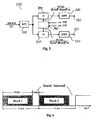
- FIG. 1 shows the block diagram of a bidirectional radio connection between a base station 10 and a customer device 20.
- the base station 10 shown in FIG. 1 and the customer device 20 can be part of a digital radio network, which can have a plurality of mobile or stationary base stations and a plurality of stationary and / or mobile customer devices.
- the base station 10 comprises, for example, two antennas 30 and 40, which are used both for receiving a digital signal from the customer device 20 (this transmission direction is also called uplink or upward direction) and for transmitting a digital signal from the base station 10 Customer device 20 (this direction of transmission is also called downlink or downward direction) can be used.
- known transceiver switches are provided which, depending on the operating mode, switch the antennas 30 and 40 into the transmitting or receiving mode.
- the antenna 30 forms the input of a first diversity branch 50
- the antenna 40 forms the input of a second diversity branch 55.
- the two diversity branches 50, 55 are in turn connected to the inputs of a signal processing device 60 which, according to the invention, carries out a diversity combination in the frequency range with the received signal of each diversity branch 50, 55, then equalizes the combined signal in the frequency range and transforms it back into the time range .
- a signal processing device 60 which, according to the invention, carries out a diversity combination in the frequency range with the received signal of each diversity branch 50, 55, then equalizes the combined signal in the frequency range and transforms it back into the time range .
- a possible circuit design and the mode of operation of the signal processing device 60 are described in detail below in connection with FIG. 2.
- the output of the signal processing device 60 is applied to a demodulator 70 which is known per se and which recovers the digital useful data from the complex baseband signal.
- the two antennas 30 and 40 working in the receive mode, the two diversity branches 50 and 55, the signal processing device 60 and the demodulator 70 together form a diversity receiver 80.
- the base station 10 also contains a transmission device 90, which in the present example also includes the two antennas 30 and 40 operating in the transmission mode.
- the transmitter 90 also includes a modulator 100 known per se, which generates the complex baseband signal from the digital useful data.
- the modulator 100 is connected to a signal processing device 110 which, according to the invention, divides the signal to be transmitted into two branches 120, 125 divides, predistorted in the frequency domain and feeds the two antennas 30 and 40.
- the transmission device 90 also has a digital-to-analog converter and a device for converting the transmission signal into the high-frequency range (not shown).
- a possible implementation of the signal conditioning device 110 in terms of circuitry and the method carried out by it are explained in more detail below in connection with FIG. 3.
- a control device 130 in the base station 10 ensures, on the one hand, that the antennas 30 and 40 are switched back and forth in the transmission or reception mode and that the signal conditioning device 110 and the signal processing device 60 are functionally controlled.
- the customer device 20 comprises, for example, a transceiver antenna 130 which is connected to a demodulator 140 known per se in the receive mode and to a modulator 150 known per se in the transmit mode.
- a generator device 160 serves to generate agreed reference symbols between the customer device 20 and the base station 10, which are sent to the base station at predetermined time intervals. The task of the reference symbols is described in detail below.
- a control device 170 ensures, on the one hand, that the transmission / reception antenna 130 is switched correctly to the transmission or reception mode and, on the other hand, to activate the generator device 160 whenever reference symbols are to be generated and transmitted to the base station 10.
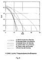
- bit error rates BER Bit Error Rate
- AWGN Additive White Gaussian Noise
- Curve b) shows the behavior for a non-frequency-selective Rayleigh channel when it is received at base station 10 with only one antenna. This behavior occurs in multi-carrier methods in both frequency-selective and frequency-selective fading channels. Based on a bit error rate of 10 -4 , there is a deterioration of about 22 dB compared to the AWGN channel.
- Curve c) shows the result when using two diversity antennas under the same channel conditions as curve b). The combination of decorrelated fading processes leads to a significant improvement compared to curve b) (approx.
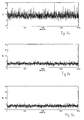
- FIGS. 4a to 4c The advantageous behavior of a diversity combination based on a maximum ratio combining approach can best be understood from FIGS. 4a to 4c.
- 4a is the amount for a transfer function of radio channel 1 and in FIG. 4b is the amount of a transfer function for radio channel 2 shown.
- the pattern functions shown in FIGS. 4a and 4b were generated with the aid of a "Typical Urban" synthetic channel model in accordance with the definitions of COST 207.
- 4c shows the resulting radio channel transfer function after the diversity combination according to the invention. While the transmission functions of the two radio channels 1 and 2 shown in FIGS. 4a and 4b have amplitude drops of up to 30 dB, the combined transfer function according to FIG. 4c only shows drops of the order of 10 dB.
- FIG. 3 shows the signal processing device 110 of the base station 10 in more detail.
- the signal processing device 110 shown in FIG. 3 is part of the transmission device 90.
- the modulated, high-frequency carrier signal coming from the modulator 100 is fed to a device 270 which transforms the time signal into the frequency range with the aid of a discrete Fourier transformation.
- the device 270 is referred to as a DFT device.
- the output of the DFT device 270 is connected to a first input of a multiplier 300 connected to branch 120 and to a first input of a second multiplier 320 connected to branch 125.
- the multiplier 300 is connected on the output side to an IDFT device 310, whereas the output of the multiplier 320 is present at the input of an IDFT device 330.
- Each IDFT device 310 and 330 carries out an inverse discrete Fourier transformation into the time domain with the transmission signal of each branch 120 or 125.
- the IDFT devices 310 and 330 can each be connected to the antenna 30 or 40 via a digital-to-analog converter and a high-frequency converter.
- a radio channel estimator 340 is configured similarly to the radio channel estimator 240 that is in the signal processing device 60 is used. An output of the radio channel estimator 340 is connected to the multiplier 300 and 320, respectively.
- the radio channel estimator 340 is therefore also able to determine the transmission functions and the associated conjugate complex transmission functions of the two radio channels 1 and 2 and the resulting radio channel transmission function. However, the radio channel estimator 340 also requires the reference symbols sent by the customer device 20.
- the time between the determination of the radio channel transmission functions and the signal transmission in downlink operation must be significantly shorter than the coherence time of radio channels 1 and 2. It is conceivable that switches 205 and 207 can be switched to a third position , so that the reference symbols can be transmitted via the DFT devices 200 and 210 to the estimating device 340. A further possibility is that the radio channel estimation device 240 of the receiving device 80 can completely take over the tasks of the radio channel estimation device 340 of the transmitting device 90 and can thus replace them. However, this is only possible if the downlink transmission of a digital signal in time duplex takes place on the same frequency as the uplink transmission. This technique is also known as time division duplex (TDD).
- TDD time division duplex
- the digital signal to be transmitted by the base station 10 is predistorted in the frequency domain by the signal processing device 110 in such a way that the signal emitted by the two antennas 30 and 40 can be received almost undistorted by the receiving antenna 130 of the customer device 20.
- the signal coming from the modulator 90 and transformed into the frequency range by the DFT device 270 is placed on the branch 120, multiplied by the conjugate complex transfer function of the radio channel 1 in the multiplier 300 and by dividing the resulting transfer function.
- the spectrum predistorted in this way passes through the IDFT device 310.
- a time signal is present at the output of the IDFT device 310, which is transmitted via the antenna 30 operating in transmission mode and via the distorted radio channel 1 to the receiving antenna 130.
- Customer setup and 20 is transferred.
- the frequency-transformed signal applied to branch 125 is multiplied by the conjugate complex transfer function of radio channel 2 in multiplier 320 and divided by the resulting transfer function.
- the signal predistorted in the frequency range then passes through the IDFT device 330.
- the time signal present at the output of the IDFT device 330 is then transmitted to the receiving antenna 130 via the antenna 40 and the distorted radio channel 2.
- the total of the predistorted signals transmitted via the distorted radio channels 1 and 2 can be received almost undistorted by the receiving antenna 130 of the customer device 20. An equalization of the received signal in the customer device 20 is therefore omitted. Therefore, the receiving device of the customer device 20 can be manufactured with a lower degree of complexity and can therefore be constructed more cost-effectively.
- FIG. 7a shows the time profile of the transmission power for 2000 transmitted signal blocks according to a downlink transmission, in which the signals in the base station 10 have been predistorted.
- the transmission power that was required for an ideal undistorted channel in order to obtain the same bit error rate as for a distorted channel (see curve a in FIG. 6) was chosen as the reference power.
- the curve shown in FIG. 7a therefore indicates the signal power that must be applied to the customer device 20 when using a single antenna at the base station 10 for a distortion-free reception. It can be seen that on average around 10 dB and in individual cases even up to 30 dB higher power must be applied. This is generally not feasible for practical use.
Landscapes
- Engineering & Computer Science (AREA)
- Computer Networks & Wireless Communication (AREA)
- Signal Processing (AREA)
- Radio Transmission System (AREA)
- Mobile Radio Communication Systems (AREA)
Applications Claiming Priority (2)
| Application Number | Priority Date | Filing Date | Title |
|---|---|---|---|
| DE1995143622 DE19543622C2 (de) | 1995-11-23 | 1995-11-23 | Verfahren und Vorrichtung zum bidirektionalen Übertragen von hochratigen Digitalsignalen |
| DE19543622 | 1995-11-23 |
Publications (2)
| Publication Number | Publication Date |
|---|---|
| EP0776101A2 true EP0776101A2 (fr) | 1997-05-28 |
| EP0776101A3 EP0776101A3 (fr) | 2000-06-07 |
Family
ID=7778182
Family Applications (1)
| Application Number | Title | Priority Date | Filing Date |
|---|---|---|---|
| EP96107315A Withdrawn EP0776101A3 (fr) | 1995-11-23 | 1996-05-09 | Procédé et dispositif de transmission bidirectionnel pour signaux numériques à haut débit utilisant une diversité d'espace |
Country Status (2)
| Country | Link |
|---|---|
| EP (1) | EP0776101A3 (fr) |
| DE (1) | DE19543622C2 (fr) |
Cited By (5)
| Publication number | Priority date | Publication date | Assignee | Title |
|---|---|---|---|---|
| WO2000027046A1 (fr) * | 1998-10-30 | 2000-05-11 | Robert Bosch Gmbh | Procede et station radio pour la transmission de signaux predistordus par l'intermediaire de plusieurs canaux radio |
| EP0975101A3 (fr) * | 1998-07-21 | 2002-11-20 | Nec Corporation | Récepteur à diversité |
| EP1292049A3 (fr) * | 2001-09-06 | 2003-07-02 | NTT DoCoMo, Inc. | Station de base et procédé de commande de communications radio avec de l'émission en diversité |
| EP1315312A3 (fr) * | 2001-10-25 | 2003-08-13 | NTT DoCoMo, Inc. | Station de base radio et procédé de commande de communications radio |
| DE102006050179A1 (de) * | 2006-10-25 | 2008-05-29 | Alcatel Lucent | Vorrichtung und Verfahren zur Emulation einer Mehrweg-Umgebung in einem Funknetz, das in einer Umgebung angeordnet ist oder diese erweitert, die frei von Mehrweg-Effekten ist |
Families Citing this family (2)
| Publication number | Priority date | Publication date | Assignee | Title |
|---|---|---|---|---|
| DE10009284A1 (de) * | 2000-02-28 | 2001-08-30 | Nokia Multimedia Terminals Oy | Schaltungsanordnung zum Durchführen von Raumdiversitybetrieb mit einem Digitalsignal-Empfänger |
| DE10027610A1 (de) * | 2000-06-06 | 2001-12-13 | Fuba Automotive Gmbh | Verfahren zum Diversityempfang von digitalen Fernsehsignalen |
Family Cites Families (6)
| Publication number | Priority date | Publication date | Assignee | Title |
|---|---|---|---|---|
| GB2045557A (en) * | 1979-03-23 | 1980-10-29 | British Broadcasting Corp | Combining electrical signals |
| DE3305797A1 (de) * | 1983-02-19 | 1984-08-23 | ANT Nachrichtentechnik GmbH, 7150 Backnang | Verfahren und anordnung zur empfangsseitigen adaptiven daempfungs- und gruppenlaufzeitsentzerrung |
| DE3508045C2 (de) * | 1985-03-07 | 1994-02-24 | Ant Nachrichtentech | Adaptiver Entzerrer für orthogonal modulierte Digitalsignale |
| GB9010637D0 (en) * | 1990-05-11 | 1990-07-04 | Secr Defence | A high frequency multichannel diversity differential phase shift(dpsk)communications system |
| US5371760A (en) * | 1993-04-28 | 1994-12-06 | Telesis Technologies Laboratory | Method and apparatus for measuring the impulse response of a radio channel |
| US5481570A (en) * | 1993-10-20 | 1996-01-02 | At&T Corp. | Block radio and adaptive arrays for wireless systems |
-
1995
- 1995-11-23 DE DE1995143622 patent/DE19543622C2/de not_active Expired - Lifetime
-
1996
- 1996-05-09 EP EP96107315A patent/EP0776101A3/fr not_active Withdrawn
Cited By (11)
| Publication number | Priority date | Publication date | Assignee | Title |
|---|---|---|---|---|
| EP0975101A3 (fr) * | 1998-07-21 | 2002-11-20 | Nec Corporation | Récepteur à diversité |
| WO2000027046A1 (fr) * | 1998-10-30 | 2000-05-11 | Robert Bosch Gmbh | Procede et station radio pour la transmission de signaux predistordus par l'intermediaire de plusieurs canaux radio |
| EP1320200A1 (fr) * | 1998-10-30 | 2003-06-18 | Robert Bosch Gmbh | Procédé de transmission de signaux entre une première et deuxième station radio |
| DE19850279B4 (de) * | 1998-10-30 | 2005-12-22 | Robert Bosch Gmbh | Verfahren für die Übertragung von Signalen zwischen einer ersten Funkstation und einer zweiten Funkstation und Funkstation |
| US7155165B1 (en) | 1998-10-30 | 2006-12-26 | Robert Bosch Gmbh | Method and radio station for the transmission of predistored signals via several radio channels |
| EP1292049A3 (fr) * | 2001-09-06 | 2003-07-02 | NTT DoCoMo, Inc. | Station de base et procédé de commande de communications radio avec de l'émission en diversité |
| US7502359B2 (en) | 2001-09-06 | 2009-03-10 | Ntt Docomo, Inc. | Radio base station and method of controlling radio communications |
| EP1315312A3 (fr) * | 2001-10-25 | 2003-08-13 | NTT DoCoMo, Inc. | Station de base radio et procédé de commande de communications radio |
| US7342943B2 (en) | 2001-10-25 | 2008-03-11 | Ntt Docomo, Inc. | Radio base station and method of controlling radio communications |
| CN100405858C (zh) * | 2001-10-25 | 2008-07-23 | 株式会社Ntt都科摩 | 无线基站和控制无线通信的方法 |
| DE102006050179A1 (de) * | 2006-10-25 | 2008-05-29 | Alcatel Lucent | Vorrichtung und Verfahren zur Emulation einer Mehrweg-Umgebung in einem Funknetz, das in einer Umgebung angeordnet ist oder diese erweitert, die frei von Mehrweg-Effekten ist |
Also Published As
| Publication number | Publication date |
|---|---|
| DE19543622C2 (de) | 1999-12-30 |
| EP0776101A3 (fr) | 2000-06-07 |
| DE19543622A1 (de) | 1997-05-28 |
Similar Documents
| Publication | Publication Date | Title |
|---|---|---|
| DE60005374T2 (de) | OFDM-System mit Sender-Antennendiversity und Vorentzerrung | |
| DE60206356T2 (de) | Orthogonale Frequenzmultiplexierung (OFDM) mit Kanalprediktion | |
| DE60220865T2 (de) | Verfahren zum OFDM-Empfang sowie Einrichtung | |
| DE69929788T2 (de) | Verfahren und vorrichtung zur diversitätsübertragung | |
| DE60303598T2 (de) | Verfahren und system für multikanalsender und empfänger mit amplituden und phasenkalibrierung | |
| DE69330964T2 (de) | Verfahren und anordnung zur dynamischen zuteilung mehrerer trägerwellenkanäle für mehrfachzugriff durch frequenzmultiplex | |
| DE69731358T2 (de) | Verfahren zur vereinfachung der demodulation in einem mehrfachträger-übertragungssystem | |
| EP2359506B1 (fr) | Procédé et dispositif d'essai d'un appareil radio mobile à l'aide d'une simulation statique de canal | |
| DE602005006423T2 (de) | Blind Selective Mapping (SLM) unter Verwendung von Pilotsignalen | |
| EP1889431B1 (fr) | Radiotransmission avec intervalle de garde de longueur variable | |
| DE60021524T2 (de) | OFDM Diversity-Übertragung | |
| DE69736659T2 (de) | Mehrträgerempfänger mit Ausgleich von Frequenzverschiebungen und von frequenzabhängigen Verzerrungen | |
| DE60125925T2 (de) | Referenzsymbole zur Kanalschätzung bei Mehrträgerübertragung | |
| DE602004006583T2 (de) | Vorrichtung und Verfahren zur Unterdrückung von Interferenzsignalen in einem System mit mehreren Antennen | |
| WO2000036769A1 (fr) | Procede et systeme de communication pour transmettre des donnees a l'aide d'un procede a ondes porteuses multiples | |
| DE102021126321A1 (de) | Sender und Empfänger für und Verfahren zum Senden und Empfangen von Symbolen über einen orthogonalen Zeit-Frequenz-Raum-Kommunikationskanal, der Dopplerspreizung und Mehrwegeausbreitung unterliegt | |
| DE202006021069U1 (de) | System für Kanalschätzung in einem Drahtlos-Kommunikationsssystem mit Delay-Diversity | |
| DE102004032667A1 (de) | Vorrichtung zum Reduzieren des Dynamikbereichs von Signalen in Sendern von Kommunikationssytemen | |
| DE19543622C2 (de) | Verfahren und Vorrichtung zum bidirektionalen Übertragen von hochratigen Digitalsignalen | |
| DE60120725T2 (de) | Teilantwortsignalisierung für ofdm | |
| DE60123282T2 (de) | Übertragen eines digitalen signals | |
| DE69936604T2 (de) | Verringerung der momentanen Maximalleistung eines Mehrträgersignals | |
| DE102022125445B3 (de) | Sender und empfänger für und verfahren zum senden und empfangen von symbolen über zeitvariable, dopplerspreizung unterliegende kanäle | |
| EP1532789B1 (fr) | Procede et dispositif d'emission permettant la transmission de donnees dans un systeme a porteuses multiples | |
| EP0687077A2 (fr) | Système de transmission radio avec stations mobiles utilisant un procédé intelligent à sauts de fréquences |
Legal Events
| Date | Code | Title | Description |
|---|---|---|---|
| PUAI | Public reference made under article 153(3) epc to a published international application that has entered the european phase |
Free format text: ORIGINAL CODE: 0009012 |
|
| AK | Designated contracting states |
Kind code of ref document: A2 Designated state(s): AT CH DE FI FR GB IT LI SE |
|
| PUAL | Search report despatched |
Free format text: ORIGINAL CODE: 0009013 |
|
| AK | Designated contracting states |
Kind code of ref document: A3 Designated state(s): AT CH DE FI FR GB IT LI SE |
|
| 17P | Request for examination filed |
Effective date: 20001207 |
|
| 17Q | First examination report despatched |
Effective date: 20060213 |
|
| 17Q | First examination report despatched |
Effective date: 20060213 |
|
| GRAP | Despatch of communication of intention to grant a patent |
Free format text: ORIGINAL CODE: EPIDOSNIGR1 |
|
| GRAS | Grant fee paid |
Free format text: ORIGINAL CODE: EPIDOSNIGR3 |
|
| STAA | Information on the status of an ep patent application or granted ep patent |
Free format text: STATUS: THE APPLICATION IS DEEMED TO BE WITHDRAWN |
|
| 18D | Application deemed to be withdrawn |
Effective date: 20070626 |