EP0776102A2 - Procédé et dispositif pour l'échange d'informations entre stations - Google Patents
Procédé et dispositif pour l'échange d'informations entre stations Download PDFInfo
- Publication number
- EP0776102A2 EP0776102A2 EP96118328A EP96118328A EP0776102A2 EP 0776102 A2 EP0776102 A2 EP 0776102A2 EP 96118328 A EP96118328 A EP 96118328A EP 96118328 A EP96118328 A EP 96118328A EP 0776102 A2 EP0776102 A2 EP 0776102A2
- Authority
- EP
- European Patent Office
- Prior art keywords
- station
- relay station
- location data
- information
- antenna
- Prior art date
- Legal status (The legal status is an assumption and is not a legal conclusion. Google has not performed a legal analysis and makes no representation as to the accuracy of the status listed.)
- Granted
Links
- 238000000034 method Methods 0.000 title claims abstract description 9
- 238000012937 correction Methods 0.000 claims description 6
- 230000005540 biological transmission Effects 0.000 description 6
- 238000005516 engineering process Methods 0.000 description 3
- 230000006870 function Effects 0.000 description 2
- 238000012545 processing Methods 0.000 description 2
- 230000002457 bidirectional effect Effects 0.000 description 1
- 238000004891 communication Methods 0.000 description 1
- 238000011161 development Methods 0.000 description 1
- 230000018109 developmental process Effects 0.000 description 1
- 230000000694 effects Effects 0.000 description 1
- 230000005284 excitation Effects 0.000 description 1
- 230000002349 favourable effect Effects 0.000 description 1
- 230000007246 mechanism Effects 0.000 description 1
- 238000005457 optimization Methods 0.000 description 1
- 230000002085 persistent effect Effects 0.000 description 1
- 230000005855 radiation Effects 0.000 description 1
- 230000035945 sensitivity Effects 0.000 description 1
- 230000008054 signal transmission Effects 0.000 description 1
- 238000012546 transfer Methods 0.000 description 1
Images

Classifications
-
- H—ELECTRICITY
- H04—ELECTRIC COMMUNICATION TECHNIQUE
- H04B—TRANSMISSION
- H04B7/00—Radio transmission systems, i.e. using radiation field
- H04B7/14—Relay systems
- H04B7/15—Active relay systems
- H04B7/185—Space-based or airborne stations; Stations for satellite systems
- H04B7/1853—Satellite systems for providing telephony service to a mobile station, i.e. mobile satellite service
- H04B7/18545—Arrangements for managing station mobility, i.e. for station registration or localisation
- H04B7/18547—Arrangements for managing station mobility, i.e. for station registration or localisation for geolocalisation of a station
- H04B7/1855—Arrangements for managing station mobility, i.e. for station registration or localisation for geolocalisation of a station using a telephonic control signal, e.g. propagation delay variation, Doppler frequency variation, power variation, beam identification
-
- F—MECHANICAL ENGINEERING; LIGHTING; HEATING; WEAPONS; BLASTING
- F41—WEAPONS
- F41G—WEAPON SIGHTS; AIMING
- F41G7/00—Direction control systems for self-propelled missiles
- F41G7/34—Direction control systems for self-propelled missiles based on predetermined target position data
-
- F—MECHANICAL ENGINEERING; LIGHTING; HEATING; WEAPONS; BLASTING
- F41—WEAPONS
- F41G—WEAPON SIGHTS; AIMING
- F41G7/00—Direction control systems for self-propelled missiles
- F41G7/34—Direction control systems for self-propelled missiles based on predetermined target position data
- F41G7/346—Direction control systems for self-propelled missiles based on predetermined target position data using global navigation satellite systems, e.g. GPS, GALILEO, GLONASS
-
- G—PHYSICS
- G01—MEASURING; TESTING
- G01S—RADIO DIRECTION-FINDING; RADIO NAVIGATION; DETERMINING DISTANCE OR VELOCITY BY USE OF RADIO WAVES; LOCATING OR PRESENCE-DETECTING BY USE OF THE REFLECTION OR RERADIATION OF RADIO WAVES; ANALOGOUS ARRANGEMENTS USING OTHER WAVES
- G01S19/00—Satellite radio beacon positioning systems; Determining position, velocity or attitude using signals transmitted by such systems
- G01S19/01—Satellite radio beacon positioning systems transmitting time-stamped messages, e.g. GPS [Global Positioning System], GLONASS [Global Orbiting Navigation Satellite System] or GALILEO
- G01S19/13—Receivers
- G01S19/14—Receivers specially adapted for specific applications
- G01S19/18—Military applications
-
- H—ELECTRICITY
- H01—ELECTRIC ELEMENTS
- H01Q—ANTENNAS, i.e. RADIO AERIALS
- H01Q1/00—Details of, or arrangements associated with, antennas
- H01Q1/27—Adaptation for use in or on movable bodies
- H01Q1/28—Adaptation for use in or on aircraft, missiles, satellites, or balloons
-
- H—ELECTRICITY
- H04—ELECTRIC COMMUNICATION TECHNIQUE
- H04B—TRANSMISSION
- H04B7/00—Radio transmission systems, i.e. using radiation field
- H04B7/14—Relay systems
- H04B7/15—Active relay systems
- H04B7/185—Space-based or airborne stations; Stations for satellite systems
- H04B7/18502—Airborne stations
-
- G—PHYSICS
- G01—MEASURING; TESTING
- G01S—RADIO DIRECTION-FINDING; RADIO NAVIGATION; DETERMINING DISTANCE OR VELOCITY BY USE OF RADIO WAVES; LOCATING OR PRESENCE-DETECTING BY USE OF THE REFLECTION OR RERADIATION OF RADIO WAVES; ANALOGOUS ARRANGEMENTS USING OTHER WAVES
- G01S19/00—Satellite radio beacon positioning systems; Determining position, velocity or attitude using signals transmitted by such systems
- G01S19/38—Determining a navigation solution using signals transmitted by a satellite radio beacon positioning system
- G01S19/39—Determining a navigation solution using signals transmitted by a satellite radio beacon positioning system the satellite radio beacon positioning system transmitting time-stamped messages, e.g. GPS [Global Positioning System], GLONASS [Global Orbiting Navigation Satellite System] or GALILEO
- G01S19/42—Determining position
-
- G—PHYSICS
- G01—MEASURING; TESTING
- G01S—RADIO DIRECTION-FINDING; RADIO NAVIGATION; DETERMINING DISTANCE OR VELOCITY BY USE OF RADIO WAVES; LOCATING OR PRESENCE-DETECTING BY USE OF THE REFLECTION OR RERADIATION OF RADIO WAVES; ANALOGOUS ARRANGEMENTS USING OTHER WAVES
- G01S5/00—Position-fixing by co-ordinating two or more direction or position line determinations; Position-fixing by co-ordinating two or more distance determinations
- G01S5/0009—Transmission of position information to remote stations
- G01S5/0045—Transmission from base station to mobile station
-
- Y—GENERAL TAGGING OF NEW TECHNOLOGICAL DEVELOPMENTS; GENERAL TAGGING OF CROSS-SECTIONAL TECHNOLOGIES SPANNING OVER SEVERAL SECTIONS OF THE IPC; TECHNICAL SUBJECTS COVERED BY FORMER USPC CROSS-REFERENCE ART COLLECTIONS [XRACs] AND DIGESTS
- Y02—TECHNOLOGIES OR APPLICATIONS FOR MITIGATION OR ADAPTATION AGAINST CLIMATE CHANGE
- Y02D—CLIMATE CHANGE MITIGATION TECHNOLOGIES IN INFORMATION AND COMMUNICATION TECHNOLOGIES [ICT], I.E. INFORMATION AND COMMUNICATION TECHNOLOGIES AIMING AT THE REDUCTION OF THEIR OWN ENERGY USE
- Y02D30/00—Reducing energy consumption in communication networks
- Y02D30/70—Reducing energy consumption in communication networks in wireless communication networks
Definitions
- the invention relates to a method according to the preamble of claim 1 and a device according to the preamble of claim 6.
- the present invention is based on the technical problem of further developing the generic measures in such a way that even a station operating under rapid changes of location works with an always optimal antenna tracking in the interest of favorable radio transmission conditions.
- the solution is therefore based on the fundamental consideration of eliminating the circuitry and, above all, dynamic problems of direction finding for antenna tracking by using a relay station with a known location on board the projectile. If your own location (e.g. via satellite navigation) and your own orientation in space are also currently known, direction information to the relay station (e.g. based on a missile-fixed coordinate system) can be calculated immediately and without bearing requirements align the missile antenna in accordance with this calculation result, preferably by way of phase control of a multiarray antenna. This antenna orientation, which is derived from two relative positions, is therefore also ready for operation when the partner station is not on the air, ie it cannot be targeted.
- direction information to the relay station e.g. based on a missile-fixed coordinate system
- This antenna orientation which is derived from two relative positions, is therefore also ready for operation when the partner station is not on the air, ie it cannot be targeted.
- the relay station is geostationary, for example in the form of a very high transmission tower or in the form of an earth-rotating rotating artificial satellite, then its location information can be permanently stored on board the projectile. If the constancy of the location coordinates of the relay station is not reliable, For example, due to path errors of a geostationary satellite per se, it is expedient for the relay station to determine any current deviation from its target position from the same satellite navigation system, which the projectile uses for its own location determination. Then, location information, expediently as correction information for the stored location information, can be transmitted from the relay station to the missile station, as a result of which the direction calculation is accelerated and, above all, the antenna orientation is further improved. This variant is of particular interest if at least one satellite with a low orbit (so-called LEO) is used as the relay station. Its standard can also be determined by the ground station and transmitted from time to time to update the position memory on board the missile.
- LEO low orbit
- a further increase in accuracy results if the ground station (with which the missile station communicates via the relay station) also makes its own position determination from time to time using the global system of navigation satellites (GPS or GLONASS). Since one's own stationary location coordinates are known with sufficient reliability, this location determination results in an error which is currently persistent in satellite navigation and which can be transmitted as current satellite correction information to specify the directional determination from the missile to the relay station, and further to the missile station.
- GPS global system of navigation satellites
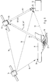
- the scenario shown in FIG. 1 is about exchanging at least one piece of information 10 between a first station 11 and a second station 12. If their antennas 21 or 22 cannot project to a greater height above the ground for reasons of practicality, then a reliable radio connection for the exchange of information 10 by means of a carrier which is typically above the VHF frequencies is not guaranteed because of the shadowing caused by uneven ground and vegetation. This applies in particular if at least one of the stations (here 11) is movable at a low height and the other (12) is installed geostationarily far away.
- Such a constellation occurs, for example, when the first station 11 is a missile operating at a low altitude (such as a reconnaissance drone or a combat helicopter) that transmits reconnaissance data or takes over operational orders as constantly and reliably as possible in a radio connection should stand with a remote ground station 12.
- a low altitude such as a reconnaissance drone or a combat helicopter
- the communication between the stations 11-12 is carried out via a third or relay station 13 positioned high above. This receives the information 10 from one station (11 or 12) and emits it again, so that it can be received and further processed almost vertically by the other station (12 or 11) and therefore practically undisturbed.
- the directional characteristics of the antennas 21-22-23 are aligned as well as possible. This is not a problem if their earth-related coordinates are known. Otherwise, the direction between the pair of transmit and receive antennas would have to be determined according to the methods of radio direction finding from a received information 10 while the partner is transmitting, in order to be able to adjust the current antenna orientations accordingly. However, this would be very time-consuming, in particular, if at least one of the stations 11, 12, 13 (as in the case of FIG. 1 for the missile station 11) is one that moves rapidly relative to at least one of the others. Because then there would be correction requirements in the antenna tracking faster than the corresponding bearing information could be determined on board from the received information 10. In addition, the additional circuitry required for direction finding is quite considerable, which has a disadvantageous effect, in particular, when designing a non-stationary station 11.
- the antenna tracking with respect to the relay station 13 does not take place via a direction bearing, but rather by taking into account the location information for the relay station 13 for the one hand and for the transmitting or receiving stations 11-12; and in particular for the very mobile missile station 11 in the scenario according to FIG. 1. Because just like the position of a ground station 12, the position of a satellite relay station 13 is also - even if it is not geostationary, but is in accordance with a known trajectory changes, as in the case of the LEOs - relatively well known.
- the own position is continuously determined on board the missile station 11 (or coupled between support points), then it is sufficient for the optimal alignment of its antenna 21, the quasi-stationary absolute position data of the missile station 11 and the relay station 13 relative to one another evaluate. In terms of equipment, this is much more economical and, above all, can be implemented much faster than conventional radio direction finding to determine the relative instantaneous direction to the radio partner.
- Navigation errors which would lead to a misalignment of the antenna 21 in the course of time, can be eliminated if the own position determined on board the missile station 11 is updated at least from time to time by contacting a locating satellite system 14. As is known, this can be used to determine the current own location with great precision, and then the exact direction from this station 11 to the location of the relay station 13.
- the relay station 13 can obtain location data 15 from the location satellite system 14 about its own current location and emit it as location data 15 'for the fine alignment of antennas 21, 22. This is particularly necessary if the relay function is not implemented at least in a quasi-stationary manner, but rather, for example, using a small aircraft (cf. the relay drone in WEHRTECHNIK 1995 number 9 page 48, bottom left).
- a phased array antenna structure is provided on board the missile station 11, in the case of an aerofoil such as a reconnaissance drone as a missile station 11, for example Surface of at least one of their wings 16 applied (Fig. 1).
- the current direction information 17 to the relay station 13 is determined on board the missile station 11 in a processor 18.
- the current own location data 15 are fed in, which are determined by a navigation receiver 19 with satellite antenna 20 on board the missile station 11.
- the flight attitude sensor system 24, which is present anyway for the missile control provides current spatial orientation information 25 (FIG. 2).
- the geostationary position of the relay station 13, which is known in principle, is carried in a memory 26.
- the location data 15 stored therein can, as described above, be checked on board the relay station 13 using the location satellite system 14 in order for the processor 18 to correct the location data 15 'if necessary, and if necessary also a current correction variable 15' 'from the ground. Station 12.
- the current directional information 17 obtained from the missile station 11 to the relay station 13 and thus from its own current position, from its own current position in space and from the known location of the relay station 13 controls a multiplex phase shifter 27 for the time-shifted excitation of the array elements, that is to say the electronically pivotable missile antenna 21, whose main direction of sensitivity is thus always exactly electronically aligned with the current relative location of the relay station 13. Therefore, there are optimal radio conditions for the information 10 transmitted there or received there, in particular for the continuous operation of a low-power transmitter or receiver 28 on board the missile station 11.
- the orientation of the missile antenna 21 can always remain directly aligned with the relay station 13 even during very fast flight maneuvers, because no time-consuming radio direction finding is realized, but rather the current position data of the communicating stations 11-13 for controlling the array Antenna 21 are compared.
- the directional information 17 can also be calculated externally (in the relay station or in the ground station 13, 12) and by radio to the antenna phase shifter 27 to be transmitted. If the swivel antenna 21 is also moved away from the missile into the relay station 13, then an unfavorable spatial instantaneous position of the rigidly oriented antenna remaining there can no longer be compensated.
Landscapes
- Engineering & Computer Science (AREA)
- Remote Sensing (AREA)
- Physics & Mathematics (AREA)
- General Physics & Mathematics (AREA)
- Computer Networks & Wireless Communication (AREA)
- Radar, Positioning & Navigation (AREA)
- Astronomy & Astrophysics (AREA)
- Aviation & Aerospace Engineering (AREA)
- General Engineering & Computer Science (AREA)
- Signal Processing (AREA)
- Chemical & Material Sciences (AREA)
- Combustion & Propulsion (AREA)
- Radio Relay Systems (AREA)
- Variable-Direction Aerials And Aerial Arrays (AREA)
Applications Claiming Priority (2)
| Application Number | Priority Date | Filing Date | Title |
|---|---|---|---|
| DE19543321A DE19543321B4 (de) | 1995-11-21 | 1995-11-21 | Verfahren und Einrichtung zum drahtlosen Austausch von Informationen zwischen Stationen |
| DE19543321 | 1995-11-21 |
Publications (3)
| Publication Number | Publication Date |
|---|---|
| EP0776102A2 true EP0776102A2 (fr) | 1997-05-28 |
| EP0776102A3 EP0776102A3 (fr) | 1999-09-01 |
| EP0776102B1 EP0776102B1 (fr) | 2005-03-02 |
Family
ID=7777982
Family Applications (1)
| Application Number | Title | Priority Date | Filing Date |
|---|---|---|---|
| EP96118328A Expired - Lifetime EP0776102B1 (fr) | 1995-11-21 | 1996-11-15 | Procédé pour l'échange d'informations entre stations |
Country Status (3)
| Country | Link |
|---|---|
| US (1) | US5880693A (fr) |
| EP (1) | EP0776102B1 (fr) |
| DE (2) | DE19543321B4 (fr) |
Cited By (3)
| Publication number | Priority date | Publication date | Assignee | Title |
|---|---|---|---|---|
| US6304574B1 (en) | 1995-06-07 | 2001-10-16 | 3Com Corporation | Distributed processing of high level protocols, in a network access server |
| DE102017105956A1 (de) | 2017-03-20 | 2018-09-20 | Riedel Communications International GmbH | Fluggerät, Funknetzwerk und Verfahren zur Übertragung von Informationen |
| CN109238253A (zh) * | 2018-09-21 | 2019-01-18 | 湖南工程学院 | 一种基于投影原理的建筑测绘方法及系统 |
Families Citing this family (27)
| Publication number | Priority date | Publication date | Assignee | Title |
|---|---|---|---|---|
| JP3052897B2 (ja) * | 1997-07-01 | 2000-06-19 | 日本電気株式会社 | 衛星捕捉・追尾装置 |
| US6751442B1 (en) | 1997-09-17 | 2004-06-15 | Aerosat Corp. | Low-height, low-cost, high-gain antenna and system for mobile platforms |
| DE19748899B4 (de) * | 1997-11-05 | 2006-10-26 | Rohde & Schwarz Gmbh & Co. Kg | System zum Betreiben von Mobiltelefonen in Verkehrsflugzeugen |
| US6023242A (en) * | 1998-07-07 | 2000-02-08 | Northern Telecom Limited | Establishing communication with a satellite |
| JP3001570B1 (ja) * | 1999-02-22 | 2000-01-24 | 埼玉日本電気株式会社 | 適応アンテナ指向性制御方法及びそのシステム |
| DE10043461B4 (de) * | 2000-09-04 | 2004-10-28 | Astrium Gmbh | Mobile Anordnung und Verfahren zur großflächigen Charakterisierung von Strahlungsfeldern im Außenbereich |
| US6750822B2 (en) | 1999-12-30 | 2004-06-15 | Astrium Gmbh | Mobile system and method for characterizing radiation fields outdoors in an extensive and precise manner |
| DE19963794B4 (de) * | 1999-12-30 | 2004-07-08 | Astrium Gmbh | Anordnung und Verfahren zur hochgenauen Winkelmessung |
| US7251223B1 (en) * | 2000-09-27 | 2007-07-31 | Aerosat Corporation | Low-height, low-cost, high-gain antenna and system for mobile platforms |
| EP1391008A1 (fr) | 2001-04-27 | 2004-02-25 | LFK-Lenkflugkörpersysteme GmbH | Elements d'antenne pour missile |
| DE10218169B4 (de) * | 2001-04-27 | 2010-12-02 | Lfk-Lenkflugkörpersysteme Gmbh | Antennenelemente für einen Flugkörper |
| AU2003245809A1 (en) | 2002-04-27 | 2003-11-17 | Eads Deutschland Gmbh | Method for data transmission between military aeroplanes and devices for carrying out said method |
| US7484257B2 (en) | 2002-07-10 | 2009-02-03 | Cimosys Ag | Electromechanical furniture drive mechanism |
| GB2393077A (en) * | 2002-09-14 | 2004-03-17 | Roke Manor Research | Aligning a directional antenna towards an access point using location information |
| WO2004107924A1 (fr) | 2003-06-05 | 2004-12-16 | Cimosys Ag | Systeme modulaire pour le montage de dispositifs de soutien, pouvant etre deplaces au moyen d'un moteur, destines au rembourrage de meubles d'assise et/ou couchage |
| GB2402553B (en) * | 2003-06-06 | 2007-06-20 | Westerngeco Seismic Holdings | A segmented antenna system for offshore radio networks and method of using the same |
| US7554482B2 (en) * | 2004-09-15 | 2009-06-30 | Aviation Communication & Surveillance Systems | Systems and methods for using a TCAS directional antenna for omnidirectional transmission |
| US7345626B2 (en) | 2004-09-15 | 2008-03-18 | Aviation Communication & Sureillance Systems, Llc | Pulse transmitters having multiple outputs in phase relationship and methods of operation |
| US7328644B2 (en) * | 2005-07-12 | 2008-02-12 | Scv Quality Solutions, Llc | System and method for intercepting a projectile |
| DE102007056661B4 (de) * | 2007-11-24 | 2015-04-02 | Mbda Deutschland Gmbh | Verfahren zur Datenkommunikation und unbemannter Flugkörper |
| WO2016026081A1 (fr) * | 2014-08-19 | 2016-02-25 | 华为技术有限公司 | Nœud d'accès, système de planification, station de base et procédé de liaison terrestre de données |
| DE202016103801U1 (de) * | 2016-07-14 | 2017-10-19 | Deutsches Zentrum für Luft- und Raumfahrt e.V. | Luftfahrzeug, Luftraumüberwachungssystem und Computerprogramm |
| JP6849065B2 (ja) | 2017-06-30 | 2021-03-24 | 村田機械株式会社 | 搬送システム及び搬送方法 |
| WO2019061311A1 (fr) * | 2017-09-29 | 2019-04-04 | 深圳市大疆创新科技有限公司 | Procédé de commande d'une voiture autonome, terminal de commande et support d'informations lisible par machine |
| CN111163416B (zh) | 2018-10-22 | 2021-05-11 | 中国移动通信有限公司研究院 | 信息获取方法、发送方法、终端及第一网络设备 |
| CN110928334B (zh) * | 2019-12-17 | 2024-11-22 | 上海电力大学 | 一种基于北斗定位的自动跟踪天线云台系统及方法 |
| CN114221900B (zh) * | 2022-01-20 | 2023-04-07 | 北京理工大学 | 一种基于弹间数据链的弹群协同信息回传方法 |
Citations (4)
| Publication number | Priority date | Publication date | Assignee | Title |
|---|---|---|---|---|
| DE2910956C2 (de) | 1979-03-21 | 1981-06-11 | Siemens AG, 1000 Berlin und 8000 München | Verfahren zur Übermittlung von Daten |
| DE3313648A1 (de) | 1983-04-15 | 1984-10-18 | Diehl GmbH & Co, 8500 Nürnberg | Verfahren zur echtzeit-gelaendeaufklaerung mittels eines sensors und einrichtung zum ausueben des verfahrens |
| GB2144008A (en) | 1983-07-05 | 1985-02-20 | Bofors Ab | Radar guided artillery shell |
| DE3720173A1 (de) | 1985-03-21 | 1989-01-05 | Donald C Knudsen | Mehrfachwandler-antennenanordnung, sowie verfahren zur richtungssteuerung des hiermit erzeugten strahls |
Family Cites Families (10)
| Publication number | Priority date | Publication date | Assignee | Title |
|---|---|---|---|---|
| US4232313A (en) * | 1972-09-22 | 1980-11-04 | The United States Of America As Represented By The Secretary Of The Navy | Tactical nagivation and communication system |
| US4622557A (en) * | 1984-10-31 | 1986-11-11 | The United States Of America As Represented By The Secretary Of The Air Force | Transdigitizer for relaying signals from global positioning system (GPS) satellites |
| US5046006A (en) * | 1989-02-28 | 1991-09-03 | Raoul D. Revord | Mutual missile control system |
| US4954829A (en) * | 1989-03-28 | 1990-09-04 | Hughes Aircraft Company | Data link using electronically steerable beam |
| US5347286A (en) * | 1992-02-13 | 1994-09-13 | Trimble Navigation Limited | Automatic antenna pointing system based on global positioning system (GPS) attitude information |
| US5340056A (en) * | 1992-02-27 | 1994-08-23 | The State Of Israel, Ministry Of Defence, Rafael Armament Development Authority | Active defense system against tactical ballistic missiles |
| CA2110205C (fr) * | 1992-11-30 | 1999-11-23 | Noboru Toyama | Recepteur mobile pour la diffusion par satellite |
| US5463656A (en) * | 1993-10-29 | 1995-10-31 | Harris Corporation | System for conducting video communications over satellite communication link with aircraft having physically compact, effectively conformal, phased array antenna |
| US5594454A (en) * | 1994-04-13 | 1997-01-14 | The Johns Hopkins University | Global positioning system (GPS) linked satellite and missile communication systems |
| US5644318A (en) * | 1996-02-02 | 1997-07-01 | Trimble Navigation Limited | SATPS dynamic surveying from a moving platform |
-
1995
- 1995-11-21 DE DE19543321A patent/DE19543321B4/de not_active Expired - Fee Related
-
1996
- 1996-11-05 US US08/746,006 patent/US5880693A/en not_active Expired - Fee Related
- 1996-11-15 DE DE59611203T patent/DE59611203D1/de not_active Expired - Lifetime
- 1996-11-15 EP EP96118328A patent/EP0776102B1/fr not_active Expired - Lifetime
Patent Citations (4)
| Publication number | Priority date | Publication date | Assignee | Title |
|---|---|---|---|---|
| DE2910956C2 (de) | 1979-03-21 | 1981-06-11 | Siemens AG, 1000 Berlin und 8000 München | Verfahren zur Übermittlung von Daten |
| DE3313648A1 (de) | 1983-04-15 | 1984-10-18 | Diehl GmbH & Co, 8500 Nürnberg | Verfahren zur echtzeit-gelaendeaufklaerung mittels eines sensors und einrichtung zum ausueben des verfahrens |
| GB2144008A (en) | 1983-07-05 | 1985-02-20 | Bofors Ab | Radar guided artillery shell |
| DE3720173A1 (de) | 1985-03-21 | 1989-01-05 | Donald C Knudsen | Mehrfachwandler-antennenanordnung, sowie verfahren zur richtungssteuerung des hiermit erzeugten strahls |
Non-Patent Citations (1)
| Title |
|---|
| "Relais-Drohne", WEHRTECHNIK, vol. 9, 1995, pages 48 |
Cited By (4)
| Publication number | Priority date | Publication date | Assignee | Title |
|---|---|---|---|---|
| US6304574B1 (en) | 1995-06-07 | 2001-10-16 | 3Com Corporation | Distributed processing of high level protocols, in a network access server |
| DE102017105956A1 (de) | 2017-03-20 | 2018-09-20 | Riedel Communications International GmbH | Fluggerät, Funknetzwerk und Verfahren zur Übertragung von Informationen |
| CN109238253A (zh) * | 2018-09-21 | 2019-01-18 | 湖南工程学院 | 一种基于投影原理的建筑测绘方法及系统 |
| CN109238253B (zh) * | 2018-09-21 | 2020-12-01 | 湖南工程学院 | 一种基于投影原理的建筑测绘方法及系统 |
Also Published As
| Publication number | Publication date |
|---|---|
| DE59611203D1 (de) | 2005-04-07 |
| EP0776102B1 (fr) | 2005-03-02 |
| DE19543321A1 (de) | 1997-05-22 |
| EP0776102A3 (fr) | 1999-09-01 |
| DE19543321B4 (de) | 2006-11-16 |
| US5880693A (en) | 1999-03-09 |
Similar Documents
| Publication | Publication Date | Title |
|---|---|---|
| EP0776102B1 (fr) | Procédé pour l'échange d'informations entre stations | |
| US6631871B2 (en) | High altitude platform control system | |
| DE3426851C1 (de) | Satelliten-Navigationssystem | |
| DE69624040T2 (de) | Selbst-überwachende GPS gebrauchende Waffenlenkung | |
| DE3854795T2 (de) | Radarsystem mit einer Gruppe von untereinander verbundenen Elementar-Satelliten | |
| EP3289385B1 (fr) | Dispositif et procédé permettant de produire et de fournir des informations de position | |
| US20080018534A1 (en) | Electronic beam steering for keyhole avoidance | |
| US20060035588A1 (en) | Low data rate mobile platform communication system and method | |
| EP0423162B1 (fr) | Systeme geodesique avec une station electrooptique totale et une station mobile de reception pour systemes de positionnement de satellites | |
| DE102017130624A1 (de) | Fahrzeug-positionsbestimmungssystem mit verwendung von v2x-, sensor- und gnss-informationen | |
| WO2019011919A1 (fr) | Satellite de navigation, notamment pour une orbite terrestre moyenne | |
| DE60008845T2 (de) | Kombiniertes Roll-Gier-Raumfahrzeugsteuerungsverfahren für den Ausgleich einer niedrigen Umlaufbahn | |
| DE102017006875A1 (de) | Systeme und Vorrichtungen zur Steuerung der Antennen-Azimut-Orientierung bei einem omnidirektionalen unbemannten Luftfahrzeug | |
| EP1499848B1 (fr) | Procede d'echange de donnees utiles entre des avions militaires, et dispositif pour mettre en oeuvre le procede | |
| DE2702340C3 (de) | Schiffsantenne | |
| EP0146857A2 (fr) | Objet volant pour brouiller des installations radio terrestres | |
| EP0635698B1 (fr) | Procédé et dispositif pour la prolongation de la durée de communication de véhicules spatiaux | |
| DE1168513B (de) | Verfahren zur Stabilisierung und Lenkung eines Flugkoerpers mit Hilfe hochfrequenter elektrischer Schwingungen | |
| EP2080981B1 (fr) | Missile sans équipage | |
| EP1777159A1 (fr) | Ensemble et procédé de détermination de position et d'attitude d'un véhicule volant, en particulier d'un véhicule spatial | |
| WO2009000732A2 (fr) | Procédé et système permettant d'améliorer la précision du positionnement | |
| DE10220440C1 (de) | Verfahren zur bordautonomen Vorhersage des zu erwartenden Auftreffpunktes einer Höhenforschungsrakete und Einrichtung zur Durchführung des Verfahrens | |
| DE1548415A1 (de) | Ortungs- und Leitverfahren fuer Flugkoerper | |
| EP1801610B1 (fr) | Système destiné à déterminer la localisation d'abonnés à un système de téléphone mobile par satellite | |
| DE19505527A1 (de) | Verfahren und Einrichtung zur Ziel- oder Lageaufklärung |
Legal Events
| Date | Code | Title | Description |
|---|---|---|---|
| PUAI | Public reference made under article 153(3) epc to a published international application that has entered the european phase |
Free format text: ORIGINAL CODE: 0009012 |
|
| AK | Designated contracting states |
Kind code of ref document: A2 Designated state(s): DE FR GB |
|
| RAP1 | Party data changed (applicant data changed or rights of an application transferred) |
Owner name: DIEHL STIFTUNG & CO. |
|
| PUAL | Search report despatched |
Free format text: ORIGINAL CODE: 0009013 |
|
| AK | Designated contracting states |
Kind code of ref document: A3 Designated state(s): DE FR GB |
|
| RIC1 | Information provided on ipc code assigned before grant |
Free format text: 6H 04B 7/185 A, 6F 41G 7/30 B, 6F 41G 7/34 B |
|
| 17P | Request for examination filed |
Effective date: 19990925 |
|
| RAP1 | Party data changed (applicant data changed or rights of an application transferred) |
Owner name: DIEHL STIFTUNG & CO. KG |
|
| 17Q | First examination report despatched |
Effective date: 20030916 |
|
| RIC1 | Information provided on ipc code assigned before grant |
Ipc: 7F 41G 7/34 A |
|
| GRAP | Despatch of communication of intention to grant a patent |
Free format text: ORIGINAL CODE: EPIDOSNIGR1 |
|
| RTI1 | Title (correction) |
Free format text: METHOD FOR WIRELESS EXCHANGE OF INFORMATION BETWEEN STATIONS |
|
| GRAS | Grant fee paid |
Free format text: ORIGINAL CODE: EPIDOSNIGR3 |
|
| GRAA | (expected) grant |
Free format text: ORIGINAL CODE: 0009210 |
|
| AK | Designated contracting states |
Kind code of ref document: B1 Designated state(s): DE FR GB |
|
| REG | Reference to a national code |
Ref country code: GB Ref legal event code: FG4D Free format text: NOT ENGLISH |
|
| REF | Corresponds to: |
Ref document number: 59611203 Country of ref document: DE Date of ref document: 20050407 Kind code of ref document: P |
|
| GBT | Gb: translation of ep patent filed (gb section 77(6)(a)/1977) |
Effective date: 20050404 |
|
| ET | Fr: translation filed | ||
| PLBE | No opposition filed within time limit |
Free format text: ORIGINAL CODE: 0009261 |
|
| STAA | Information on the status of an ep patent application or granted ep patent |
Free format text: STATUS: NO OPPOSITION FILED WITHIN TIME LIMIT |
|
| 26N | No opposition filed |
Effective date: 20051205 |
|
| PGFP | Annual fee paid to national office [announced via postgrant information from national office to epo] |
Ref country code: FR Payment date: 20131120 Year of fee payment: 18 Ref country code: GB Payment date: 20131120 Year of fee payment: 18 |
|
| PGFP | Annual fee paid to national office [announced via postgrant information from national office to epo] |
Ref country code: DE Payment date: 20140122 Year of fee payment: 18 |
|
| REG | Reference to a national code |
Ref country code: DE Ref legal event code: R119 Ref document number: 59611203 Country of ref document: DE |
|
| GBPC | Gb: european patent ceased through non-payment of renewal fee |
Effective date: 20141115 |
|
| REG | Reference to a national code |
Ref country code: FR Ref legal event code: ST Effective date: 20150731 |
|
| PG25 | Lapsed in a contracting state [announced via postgrant information from national office to epo] |
Ref country code: DE Free format text: LAPSE BECAUSE OF NON-PAYMENT OF DUE FEES Effective date: 20150602 Ref country code: GB Free format text: LAPSE BECAUSE OF NON-PAYMENT OF DUE FEES Effective date: 20141115 |
|
| PG25 | Lapsed in a contracting state [announced via postgrant information from national office to epo] |
Ref country code: FR Free format text: LAPSE BECAUSE OF NON-PAYMENT OF DUE FEES Effective date: 20141201 |