EP0776143A1 - System zur Regulierung von Informationsströmen für eine Paketenvermittlungsstelle - Google Patents
System zur Regulierung von Informationsströmen für eine Paketenvermittlungsstelle Download PDFInfo
- Publication number
- EP0776143A1 EP0776143A1 EP96402495A EP96402495A EP0776143A1 EP 0776143 A1 EP0776143 A1 EP 0776143A1 EP 96402495 A EP96402495 A EP 96402495A EP 96402495 A EP96402495 A EP 96402495A EP 0776143 A1 EP0776143 A1 EP 0776143A1
- Authority
- EP
- European Patent Office
- Prior art keywords
- module
- output
- input
- packet
- channel
- Prior art date
- Legal status (The legal status is an assumption and is not a legal conclusion. Google has not performed a legal analysis and makes no representation as to the accuracy of the status listed.)
- Granted
Links
Images




Classifications
-
- H—ELECTRICITY
- H04—ELECTRIC COMMUNICATION TECHNIQUE
- H04L—TRANSMISSION OF DIGITAL INFORMATION, e.g. TELEGRAPHIC COMMUNICATION
- H04L49/00—Packet switching elements
- H04L49/50—Overload detection or protection within a single switching element
- H04L49/505—Corrective measures
- H04L49/508—Head of Line Blocking Avoidance
-
- H—ELECTRICITY
- H04—ELECTRIC COMMUNICATION TECHNIQUE
- H04L—TRANSMISSION OF DIGITAL INFORMATION, e.g. TELEGRAPHIC COMMUNICATION
- H04L49/00—Packet switching elements
- H04L49/30—Peripheral units, e.g. input or output ports
-
- H—ELECTRICITY
- H04—ELECTRIC COMMUNICATION TECHNIQUE
- H04L—TRANSMISSION OF DIGITAL INFORMATION, e.g. TELEGRAPHIC COMMUNICATION
- H04L49/00—Packet switching elements
- H04L49/30—Peripheral units, e.g. input or output ports
- H04L49/3081—ATM peripheral units, e.g. policing, insertion or extraction
-
- H—ELECTRICITY
- H04—ELECTRIC COMMUNICATION TECHNIQUE
- H04L—TRANSMISSION OF DIGITAL INFORMATION, e.g. TELEGRAPHIC COMMUNICATION
- H04L49/00—Packet switching elements
- H04L49/50—Overload detection or protection within a single switching element
- H04L49/501—Overload detection
- H04L49/503—Policing
-
- H—ELECTRICITY
- H04—ELECTRIC COMMUNICATION TECHNIQUE
- H04Q—SELECTING
- H04Q11/00—Selecting arrangements for multiplex systems
- H04Q11/04—Selecting arrangements for multiplex systems for time-division multiplexing
- H04Q11/0428—Integrated services digital network, i.e. systems for transmission of different types of digitised signals, e.g. speech, data, telecentral, television signals
- H04Q11/0478—Provisions for broadband connections
-
- H—ELECTRICITY
- H04—ELECTRIC COMMUNICATION TECHNIQUE
- H04L—TRANSMISSION OF DIGITAL INFORMATION, e.g. TELEGRAPHIC COMMUNICATION
- H04L12/00—Data switching networks
- H04L12/54—Store-and-forward switching systems
- H04L12/56—Packet switching systems
- H04L12/5601—Transfer mode dependent, e.g. ATM
- H04L2012/5619—Network Node Interface, e.g. tandem connections, transit switching
-
- H—ELECTRICITY
- H04—ELECTRIC COMMUNICATION TECHNIQUE
- H04L—TRANSMISSION OF DIGITAL INFORMATION, e.g. TELEGRAPHIC COMMUNICATION
- H04L12/00—Data switching networks
- H04L12/54—Store-and-forward switching systems
- H04L12/56—Packet switching systems
- H04L12/5601—Transfer mode dependent, e.g. ATM
- H04L2012/5629—Admission control
- H04L2012/5631—Resource management and allocation
- H04L2012/5636—Monitoring or policing, e.g. compliance with allocated rate, corrective actions
-
- H—ELECTRICITY
- H04—ELECTRIC COMMUNICATION TECHNIQUE
- H04L—TRANSMISSION OF DIGITAL INFORMATION, e.g. TELEGRAPHIC COMMUNICATION
- H04L12/00—Data switching networks
- H04L12/54—Store-and-forward switching systems
- H04L12/56—Packet switching systems
- H04L12/5601—Transfer mode dependent, e.g. ATM
- H04L2012/5678—Traffic aspects, e.g. arbitration, load balancing, smoothing, buffer management
- H04L2012/5679—Arbitration or scheduling
Definitions
- the present invention relates to an information train control system for a packet switch.
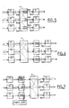
- FIG. 1 shows the block diagram of a device for regulating information trains within a switch.
- a device mainly comprises input modules, output modules and a routing module.
- these modules are each produced in the form of a standard format electronic card.
- Each input module receives on its input port a sporadic or non-sporadic high speed information train.
- Each module, input or output card has two ports, an input port and an output port.
- the routing module has at least as many input ports respectively, output ports, as input cards respectively, output cards.
- a switch input link provides an input port for an input card.
- a port consists of a channel which supports several channels forming an interlacing of information trains knowing that there is only one cell on the channel. Information trains return asynchronously and exit asynchronously.
- FIG. 2 shows interleaving of information trains circulating through an input card or through an output card.
- this diagram illustrates the arrival of three information trains on the debit input port DE of the card and the output of these three information trains on the debit output port DS of the card.
- the numbers 1 and 2 mark the order of cells within the same train. We can see that the order of the packets on each information train is the same at the output as at the input.
- a flow of information is associated with a flow (this is the number of cells per second) which is also the flow of the channel on which it circulates.
- a port is associated with a speed (limit value of the number of cells per second regardless of the information trains to which these cells belong).
- the input rate DE of an input card is generally equal to the output rate DS of this card, it can also be lower.
- active channel for a card means a channel for which there are cells in this card (this notion of active channel is therefore internal to a switch).
- a switch then has the possibility of indicating to its upstream switch to reduce the bit rates of the channels coming from the output cards of the latter.
- An output card from the upstream switch is then associated with an input card from the switch in question.
- the referral module is able to process the sum of the incoming flows, its function consists in sending a data stream from a port i to a port j over the water. Information streams from different input ports may be routed to the same output module.
- the first solution consists in placing a buffer at the outlet of the switch. In practical terms, this amounts to placing a large memory on each output port.
- the memory size is a function of the number of inputs and of the flow so as to buffer the excess flow at the output of the switch.
- the memories are placed between the output port of the switch and the output card as shown in FIG. 6.
- the size of the buffer necessary to accumulate the excess flow increases linearly according to the relationship: (n-1) x D x T, with n the number of inputs of the switch, D the flow of the input ports of the switch and the output port (case B) or the input of the output card (case A), T the duration during which the simultaneity of convergence occurs.
- a buffer size of 1400 cells is necessary to accumulate the flow over the duration of a train (140 ⁇ s), and increases linearly as long as this simultaneity of convergence continues (eg on several trains).
- the second solution consists in placing a buffer at the input of the switcher and using a resource reservation mechanism.
- a buffer is placed on each input of the switch.
- the entry cards call on a central body which is aware of all the switch needs in terms of speed. This member regulates the output flows of the buffers so that there is no overflow at the output of the switch. This solution is illustrated in Figure 7.
- the maximum buffer size is no more than: DxT with D the speed of the input port of the input card, T the period during which the central body no longer authorizes this card to be issued (it is is a worse case, the central body having to ensure that the buffers flow out as well as possible).
- rhythm generators to execute the orders of the central organ.
- one approach consists in placing several buffers on each input of the switchman; as many buffers are placed on each entry as there are possible exit directions.
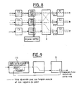
- a central body regulates the output flows of the buffers so that there is no overflow at the output of the switch. This is illustrated by the diagram in Figure 8.
- the central organ does not take into account the channels individually, and if one wishes to place the cells on each output link, according to a particular rule by distinguishing the channels to which they belong, it is necessary to have a device placed in each output card arbitrating each of the channels that the card supports. To this mechanism Arbitration is then added that regulating the output rates of the buffers at the switch input.
- a third and final solution is to place a stamp at the exit of the entry cards and use a credit mechanism.
- Buffers are placed on each entry card exit; as many buffers are placed on each output as there are channels supported by the input card.
- Figure 9 illustrates the credit mechanism per channel, between exit cards and entry cards.
- the buffer and the credit register associated with a particular channel in an entry card are represented (in fact, there are as many buffers and credit registers as there are channels supported by an entry card) .
- an entry card can send a packet (or cell) belonging to a connection when the credit for this channel is not zero.
- the credit value of the channel After transmission of a cell by the input card the credit value of the channel is decremented by 1. After emission of a cell for this channel, by the output card, the credit value of the channel is incremented from 1.
- each jump through the matrix for a channel is managed by a credit algorithm.
- One of the advantages is that there are no additional rhythm generators in the entry cards, which only emit when credits are available.
- Another interest is the independence of operation of the different cards; there is no centralized management.
- This method does not completely solve the blocking problem at the exit of the switch. Indeed, in the case where a lot of credits are concentrated in the entry cards (this situation can occur at startup, but also during normal operation) and in cases where simultaneously several cards decide to use their credits for channels going to the same output card, there will be overflow of the matrix buffers in case B or saturation of the input of the output card in case A.
- the excess flow that must then be stored in buffers at the switch output is: (n-1) x D with n the number of inputs that simultaneously emit D the speed of the input ports of the switch and the output port (case B) or of the input of the output card (case A).
- T cx V x 1 / D, with c the number of credits, V the number of channels supported by an input card and going to the same exit card (taking place in the case where credits within the same entry card, for the channels going on the same exit card, are used successively).
- the size of 7200 cells corresponds to the result obtained from the relationship defined in the first solution for a time T necessary to sell 300 trains of 3 cells (3 being the credit value, and not 200 cells).
- the object of the present invention is to resolve these drawbacks.
- it is not necessary to add large memories at the output of the switch, there is no centralized system, and only one arbitration body is implemented in each output card regardless of the arbitration rule.
- the present invention more particularly relates to an information train regulation system for packet switch according to which a queue is provided per channel of each input module capable of being piloted by an arbiter placed in each of the modules. output supporting these channels.
- each input module (Ei) comprises a member capable of transmitting an indication of presence or absence of packet (P / A) for each channel supported by this module in the direction of the output modules supporting these channels .
- the system includes a communications bus (BD) for the exchange of signals (P / A, DE) between the input and output module of the system, this bus directly interconnects all the input modules to all the output modules.
- BD communications bus
- Each input module (Ei) comprises a set comprising a queue per channel, a member for accessing the queues and for managing these queues capable of transmitting indications of presence or absence of packets and a packet extraction unit responding to transmission requests (DE).
- the access and queue management unit and the packet extraction unit are produced by a packet processor associated with a channel context memory which matches each packet with its channel number, and by a body for processing transmission requests (DE) received and for generating presence or absence of packets (P / A).
- a packet processor associated with a channel context memory which matches each packet with its channel number
- a body for processing transmission requests (DE) received and for generating presence or absence of packets (P / A).
- the unit for processing transmission requests (DE) and for generating presence or absence of packets (P / A) comprises a reception and processing device for receiving several transmission requests (DE) in order of d arrival from different output modules and processes a single request (DE) at the output rate (Te) of the module input, among those received in order to send on the output port a packet belonging to the channel associated with the transmission request processed.
- the access unit to the queues and packet extraction further comprises a communication unit with the dialogue bus (BD) to store the transmission requests (DE) addressed to it and put them on hold indications of presence or absence of packet (P / A) as long as the bus is not available.
- BD dialogue bus
- DE transmission requests
- P / A hold indications of presence or absence of packet
- the communication device includes a dialogue bus management processor (BD), two batteries (702), one of which receives the transmission requests (DE) from the various output modules and the other the presence or no packet relating to each channel supported by the input module and a control circuit for comparing the information received from the identification of the recipient module with its own identification and thus knowing whether the dialogue bus is available for this module entry.
- BD dialogue bus management processor
- DE transmission requests
- the control system also includes a dialogue bus arbiter (BD) responsible for supplying the sequencing signals for reads and writes on this dialogue bus.
- BD dialogue bus arbiter
- Each output module (Si) comprises a packet processor associated with a channel context memory, the arbiter making it possible to generate the transmission requests and to process the indications of presence or absence of packets received according to the rule d pre-established arbitration.
- Each output module includes a communication device for dialogue with the dialogue bus (BD) to store the indications of presence or absence of packet (P / A) which are sent to it by the various input modules and put pending packet transmission requests (DE) to different input modules as long as the bus is not available.
- BD dialogue bus
- P / A indications of presence or absence of packet
- DE packet transmission requests
- the communication device comprises two batteries, one of which is used to store the indications of presence or absence of packets and the other the transmission requests and a control circuit receiving identification information from the module and comparing this information to its own identification and thus know if the dialog bus is available for this output module.
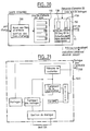
- FIG. 10 represents the different functional blocks provided by each of the constituent members of the switch.
- Each input module E1-EN has a set of access to the queues and management of the queues 100, a set of queues 110 and a set of packet extraction according to the requests for Show of.
- Each output module S1-SM comprises an arbiter 500 controlled by a clock 510 and a packet transmission unit 520 according to the output bit rate.
- the switch A passes the information train circulating on channel 1,1,1 received on the input port of the module El by the output module S1.
- a packet presence indication for this channel is sent on a BD dialogue bus between input modules and output modules, to the output module which also supports this path.
- a context table specific to each module and addressed by the channel identifier makes it possible to find the number of the output module. If the queue of a channel is not empty when a packet arrives, it is not useful to generate a packet presence indication.
- the arrival of the packet presence indication via the dialogue bus BD, authorizes the generation of transmission requests DE for this channel.
- Arbitrator 500 manages all of the transmission requests for the channels that the output card supports.
- Te working period of the input module
- the arrival of the packet absence indication causes the suppression of transmission requests for the channel (as long as there is no reception of packet presence indication for this channel ).
- the arbiter in the output module no longer selects this channel.
- the dialogue between input module and output module with regard to information other than the data streams, therefore does not pass through the switch, but is done by a bus dedicated to this dialogue which has been referenced BD.
- the packet presence or non-presence indications circulate, going from the input modules to the output modules, and the transmission requests, going from the output modules to the input modules.
- the identification of the channel to which it corresponds and the identification of the card receiving the information are provided.
- the arbiter 500 located in the output module regulates the information trains belonging to the different channels that the output module supports.
- This arbiter operates at the rate of the output flow from the output module.
- the arbiter 500 chooses a channel so that it transmits a packet from the input module. For this, the arbitrator generates a request for DE transmission for this channel, and communicates it via the dialogue bus to the output module which supports the channel.
- Arbitrator 500 is aware of the state of the queues in the input modules (i.e. whether or not there are packets in the queue). Indeed, an indication of packet presence or non-presence of packet P / A is sent by an input module at each change of state of a queue, to the output module which supports the associated channel (and this for each queues supported by the input module).
- the input module receives transmission requests DE from different output modules, via the dialogue bus BD.
- the input module manages the DE transmission requests at the rate of the output flow from the input module.
- the module processes a single transmission request among those received from the output modules, and transmits on its output port a packet belonging to the channel associated with the transmission request processed .
- a request for transmission DE arrives on an input module while this module has just sent an indication of no packet presence for the associated channel (ie its buffer has just been emptied) then the transmission request is destroyed as soon as it is received in the entry card.
- the switch also includes additional functions such as communication between switches.
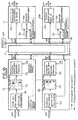
- an upstream switch output module Associated with a switch input module is an upstream switch output module, as illustrated in FIG. 11.
- the switch observes its packet queues, and depending on their level of occupancy, requests the upstream switch reduce or increase their flow.
- an output module supports queues whose channels come from different switches. It is therefore necessary to operate a reverse switch in order to determine the upstream switch which supports the queues.
- the rate reduction / increase request information is sent directly to the switch associated with the input module, then the upstream switch routes this information to the output module concerned; the arbitrator takes this into account when generating requests.
- the switch is also able to implement a pre-established transmission rule on the output link.
- the selection of a request gives rise directly to a transmission request for the channel associated with the request: if it is a Dmg request (respectively Dc request), a DE Dmg (respectively DE Dc) is generated .
- the DE Dmg At the level of an input module, the DE Dmg will be treated as a priority to the DE Dc whatever the channels associated with them.
- channel i If a congestion notification for channel i is received, there is no Dc request generation for channel i as long as the congestion situation occurs, (channel i can only be selected by the first referee). Thus the channel i is limited to the flow Dmg, and does not participate in the reallocation.
- These functional assemblies are both produced by a packet processor 132 associated with a context memory of the channels 133, and with a member for processing transmission requests, received through a member for communication with the dialogue bus, and for generation of packet presence or absence 130.
- the processor 132 is connected to the switcher by the bus B used to transport the packets of each channel which are waiting in the queues.
- the output modules (S1, SN), FIG. 14, comprise an arbiter 500 controlled by an internal clock 510 and a functional assembly for the transmission of packets (according to the output rate of the module) articulated around a processor 530.
- the packet processor is associated with a channel 532 context memory.
- a member 531 for communication with the dialogue bus makes it possible to receive the indications of presence or absence of packets and to send the transmission requests DE.
- Processor 530 receives packets from switcher A using bus B.
- the “additional" bus that is to say the dialogue bus BD is a bi-directional bus, point to multipoint, shared by all the cards.
- the bus is managed by a MOTOROLA component: marketed under the name of SPANCEIVER.
- the 16 locations likely to interact on this bus are numbered from 0 to 15.
- the cards read their location on the pins of the connector of the ATM signals e ⁇ 3..0> bus. All cards receive the BUSN ⁇ 3..0> and DOE signals.
- Arbitrator 600 is a signal generator and generates the sequencing signals for reads and writes BUSN ⁇ 3..0> and DOE represented on the timing diagram of FIG. 16 that each card (or module) receives.
- FIGS. 18 and 19 there is shown in FIGS. 18 and 19 the particular embodiment which has been made for the input cards and the output cards in the case of processing packets constituted by ATM cells.
- the packet processors 132 or 530 are ATM cell processors marketed under the name of ATMIZER.
- the memory elements for channel contexts are non-volatile memories. Memories contain the BOOT program for starting the application.
- the processor is connected to this memory 133 (or 532) by an address and data bus by its secondary port.
- the processor is connected to the DE130 request processing or DE500 request generation (referee) body via its DMA port.
- Each input or output card can be configured by means of a VME interface (not shown) from an address bus AD and of data D.
- the VME interface accesses the context memory 133 and the cell memory 110 by these buses D and AD.
- the VME interface accesses the context memory 532 by these buses D and AD.
- FIG. 20 illustrates, according to these embodiments, the management of DE transmission requests.
- This is the unit 130 for processing transmission requests, and for generating packet presence / absence indications.
- the purpose of the ED management mechanism is to compensate for the simultaneity of arrival on the same entry card of several DEs for different exit cards.
- Two queues are used for this per entry card: a fifo stack 13A for requests for transmission of reallocation DE Dc and a fifo stack 13B for requests for transmission DE Dmg at the clock Dmg.
- the fifo of DE requests at the clock Dmg (and respectively the queue of DE Dc) is common to all the channels supported by the input card.
- the processor has several counters associated with a channel (and therefore with a packet queue no. I):
- CCI Cell Counter (represents the number of cells actually contained in the queue associated with the channel) is used for the notification protocol and memory management.
- CPC Potential Cell Counter (represents the number of cells actually contained in the queue associated with the channel minus the total number of Dmg + Dc for this channel).
- the following mechanism is implemented so that there are no unnecessary DEs for channel i.
- the cells in the CPC queue are counted, and a DE Dc is destroyed as soon as the total DE Dmg + DE Dc for the channel has reached the number of cells in the queue associated with the channel.
- any new DE Dc received is destroyed. If it is a DE Dmg the principle consists in replacing a DE Dc (already received and not yet used) for the channel by the DE Dmg which has just been received.
- DE Dmg have priority over DE Dc.
- a first arbitrator deals with DE Dmg requests and includes a fifo of DE Dmg 501.
- a second arbitrator 502 in charge of reallocation, puts implement a round of Dc requests. It is made up of a table with a predefined number of boxes. A box is marked with a channel number. When a box is selected, if it is marked it gives rise to a DE Dc for this channel.
Landscapes
- Engineering & Computer Science (AREA)
- Computer Networks & Wireless Communication (AREA)
- Signal Processing (AREA)
- Data Exchanges In Wide-Area Networks (AREA)
Applications Claiming Priority (2)
| Application Number | Priority Date | Filing Date | Title |
|---|---|---|---|
| FR9513963A FR2741763B1 (fr) | 1995-11-23 | 1995-11-23 | Systeme de regulation de trains d'information pour commutateur paquet |
| FR9513963 | 1995-11-23 |
Publications (2)
| Publication Number | Publication Date |
|---|---|
| EP0776143A1 true EP0776143A1 (de) | 1997-05-28 |
| EP0776143B1 EP0776143B1 (de) | 2003-02-05 |
Family
ID=9484873
Family Applications (1)
| Application Number | Title | Priority Date | Filing Date |
|---|---|---|---|
| EP96402495A Expired - Lifetime EP0776143B1 (de) | 1995-11-23 | 1996-11-20 | System zur Regulierung von Informationsströmen für eine Paketvermittlungsstelle |
Country Status (5)
| Country | Link |
|---|---|
| US (1) | US6266338B1 (de) |
| EP (1) | EP0776143B1 (de) |
| CA (1) | CA2190927A1 (de) |
| DE (1) | DE69626090T2 (de) |
| FR (1) | FR2741763B1 (de) |
Families Citing this family (7)
| Publication number | Priority date | Publication date | Assignee | Title |
|---|---|---|---|---|
| US6985964B1 (en) * | 1999-12-22 | 2006-01-10 | Cisco Technology, Inc. | Network processor system including a central processor and at least one peripheral processor |
| KR100321784B1 (ko) * | 2000-03-20 | 2002-02-01 | 오길록 | 중재 지연 내성의 분산형 입력 버퍼 스위치 시스템 및그를 이용한 입력 데이터 처리 방법 |
| US7002996B1 (en) * | 2001-04-09 | 2006-02-21 | Applied Micro Circuits Corporation | System and method for switch timing synchronization |
| US6721312B2 (en) * | 2001-06-01 | 2004-04-13 | Pluris, Inc. | Method and apparatus for improving data transmission in router fabric cards through pseudo-synchronous data switching |
| JP4111259B2 (ja) * | 2001-09-25 | 2008-07-02 | 株式会社リコー | 符号化装置、符号化方法、ソフトウェアプログラム、テーブルデータ並びに記録媒体 |
| KR100459036B1 (ko) * | 2001-12-18 | 2004-12-03 | 엘지전자 주식회사 | 에이티엠 스위치 시스템의 트레인 패킷 구성 방법 |
| KR101090440B1 (ko) * | 2003-12-08 | 2011-12-06 | 삼성전자주식회사 | 데이터 통신 시스템의 수신기에서 버퍼 데이터량 조정장치및 방법, 적응적 클럭 동기부를 갖는 실시간 데이터재생장치 및 방법 |
Citations (1)
| Publication number | Priority date | Publication date | Assignee | Title |
|---|---|---|---|---|
| US5267235A (en) * | 1992-05-21 | 1993-11-30 | Digital Equipment Corporation | Method and apparatus for resource arbitration |
Family Cites Families (3)
| Publication number | Priority date | Publication date | Assignee | Title |
|---|---|---|---|---|
| KR900006793B1 (ko) * | 1984-10-18 | 1990-09-21 | 휴우즈 에어크라프트 캄파니 | 패킷 스위치 다중 대기행렬 NxM 스위치 노오드 및 처리 방법 |
| US5222085A (en) * | 1987-10-15 | 1993-06-22 | Peter Newman | Self-routing switching element and fast packet switch |
| US5001706A (en) * | 1989-06-23 | 1991-03-19 | At&T Bell Laboratories | Packet cross connect switch system including improved throughput |
-
1995
- 1995-11-23 FR FR9513963A patent/FR2741763B1/fr not_active Expired - Fee Related
-
1996
- 1996-11-20 EP EP96402495A patent/EP0776143B1/de not_active Expired - Lifetime
- 1996-11-20 DE DE69626090T patent/DE69626090T2/de not_active Expired - Lifetime
- 1996-11-21 US US08/752,817 patent/US6266338B1/en not_active Expired - Fee Related
- 1996-11-21 CA CA002190927A patent/CA2190927A1/fr not_active Abandoned
Patent Citations (1)
| Publication number | Priority date | Publication date | Assignee | Title |
|---|---|---|---|---|
| US5267235A (en) * | 1992-05-21 | 1993-11-30 | Digital Equipment Corporation | Method and apparatus for resource arbitration |
Non-Patent Citations (1)
| Title |
|---|
| JONATHAN CHAO H: "A GENERAL ARCHITECTURE FOR LINK-LAYER CONGESTION CONTROL IN ATM NETWORKS", PROCEEDINGS OF THE INTERNATIONAL SWITCHING SYMPOSIUM, YOKOHAMA, OCT. 25 - 30, 1992, vol. 1 - 2, 25 October 1992 (1992-10-25), INSTITUTE OF ELECTRONICS;INFORMATION AND COMMUNICATION ENGINEERS, pages 229 - 233, XP000337649 * |
Also Published As
| Publication number | Publication date |
|---|---|
| FR2741763A1 (fr) | 1997-05-30 |
| FR2741763B1 (fr) | 1998-01-23 |
| DE69626090T2 (de) | 2003-07-31 |
| DE69626090D1 (de) | 2003-03-13 |
| US6266338B1 (en) | 2001-07-24 |
| CA2190927A1 (fr) | 1997-05-24 |
| EP0776143B1 (de) | 2003-02-05 |
Similar Documents
| Publication | Publication Date | Title |
|---|---|---|
| EP0293314B1 (de) | Verfahren und System zur Paketflusssteuerung | |
| EP1280376B1 (de) | Taskverwaltungsverfahren für einen Router einer Paketvermittlungsstelle, die Teil eines gesicherten und Paketvermittelten Netzes ist | |
| EP0293315B1 (de) | System und Verfahren zur Paketflusssteuerung | |
| CA2050405C (fr) | Systeme de memorisation temporaire d'information comprenant une memoire tampon enregistrant des donnees structurees en blocs de donnees de longueur fixe ou variable | |
| EP0300941B1 (de) | Vermittlungssystem für Informationen mit Vorrang | |
| EP0609137B1 (de) | Umwandlungsvorrichtung zwischen Asynchronen- und Synchronen Übertragungsverfahren | |
| FR2630839A1 (fr) | Procede et dispositif de controle de l'acces a un bus dans un systeme informatique | |
| FR2517442A1 (fr) | Dispositif d'interruption pour un systeme de multitraitement, procede pour sa commande et systeme pour sa mise en oeuvre | |
| EP0618749A1 (de) | Einrichtung und System zur Multiplexbildung der Information im ATM-Netz | |
| EP0478008B1 (de) | Verfahren und System zur Überwachung der Datenraten von asynchronen Zeitmultiplex-Übertragungen | |
| EP0317930B1 (de) | Vermittlungseinrichtung für im asynchronen Zeitmultiplexverfahren übertragene Daten | |
| EP0284534A1 (de) | Vermittlungssystem für hybride Zeitmultiplexe | |
| CA2108809C (fr) | Dispositif de resequencement pour un noeud d'un systeme de commutation de cellules | |
| EP0776143B1 (de) | System zur Regulierung von Informationsströmen für eine Paketvermittlungsstelle | |
| EP0300942A1 (de) | Vermittlungssystem für Datenpakete mit Vorrang | |
| FR2623953A1 (fr) | Unite de gestion pour element de commutation de donnees transmises par multiplexage temporel asynchrone | |
| EP1374465B1 (de) | Vermittlungsstelle für datenrahmen variabler grosse in sicherheits bordnetzen | |
| WO2001022684A1 (fr) | Procede et systeme de transmission d'une chaine de messages pour base de donnees | |
| EP0011540B1 (de) | Ein-/Ausgabe-Schnittstelle zwischen einem Datenvermittler und mehreren Übertragungsleitungen | |
| FR2472245A1 (fr) | Operateur autonome de gestion de files d'attente ou de memoire | |
| FR2513472A2 (fr) | Commutateur de paquets pour un reseau a commutation de paquets | |
| EP1355453A1 (de) | Anlage zur zentralisierten Schaltung und Leitweglenkung | |
| EP0403361A1 (de) | Verfahren und System zur Zellenvermittlung für asynchrone Zeitvielfachvermittlungen | |
| EP0270471B1 (de) | Paketvermittlungssystem | |
| FR2668324A1 (fr) | Methode et systeme de lissage et de controle de debits de communications temporelles asynchrones. |
Legal Events
| Date | Code | Title | Description |
|---|---|---|---|
| PUAI | Public reference made under article 153(3) epc to a published international application that has entered the european phase |
Free format text: ORIGINAL CODE: 0009012 |
|
| AK | Designated contracting states |
Kind code of ref document: A1 Designated state(s): DE GB IT |
|
| 17P | Request for examination filed |
Effective date: 19970704 |
|
| 17Q | First examination report despatched |
Effective date: 19991202 |
|
| GRAG | Despatch of communication of intention to grant |
Free format text: ORIGINAL CODE: EPIDOS AGRA |
|
| GRAG | Despatch of communication of intention to grant |
Free format text: ORIGINAL CODE: EPIDOS AGRA |
|
| GRAH | Despatch of communication of intention to grant a patent |
Free format text: ORIGINAL CODE: EPIDOS IGRA |
|
| GRAH | Despatch of communication of intention to grant a patent |
Free format text: ORIGINAL CODE: EPIDOS IGRA |
|
| GRAA | (expected) grant |
Free format text: ORIGINAL CODE: 0009210 |
|
| AK | Designated contracting states |
Designated state(s): DE GB IT |
|
| REG | Reference to a national code |
Ref country code: GB Ref legal event code: FG4D Free format text: NOT ENGLISH |
|
| GBT | Gb: translation of ep patent filed (gb section 77(6)(a)/1977) |
Effective date: 20030205 |
|
| REF | Corresponds to: |
Ref document number: 69626090 Country of ref document: DE Date of ref document: 20030313 Kind code of ref document: P |
|
| PLBE | No opposition filed within time limit |
Free format text: ORIGINAL CODE: 0009261 |
|
| STAA | Information on the status of an ep patent application or granted ep patent |
Free format text: STATUS: NO OPPOSITION FILED WITHIN TIME LIMIT |
|
| 26N | No opposition filed |
Effective date: 20031106 |
|
| PGFP | Annual fee paid to national office [announced via postgrant information from national office to epo] |
Ref country code: IT Payment date: 20071117 Year of fee payment: 12 |
|
| PG25 | Lapsed in a contracting state [announced via postgrant information from national office to epo] |
Ref country code: IT Free format text: LAPSE BECAUSE OF NON-PAYMENT OF DUE FEES Effective date: 20081120 |
|
| PGFP | Annual fee paid to national office [announced via postgrant information from national office to epo] |
Ref country code: DE Payment date: 20121130 Year of fee payment: 17 |
|
| PGFP | Annual fee paid to national office [announced via postgrant information from national office to epo] |
Ref country code: GB Payment date: 20121025 Year of fee payment: 17 |
|
| GBPC | Gb: european patent ceased through non-payment of renewal fee |
Effective date: 20131120 |
|
| PG25 | Lapsed in a contracting state [announced via postgrant information from national office to epo] |
Ref country code: DE Free format text: LAPSE BECAUSE OF NON-PAYMENT OF DUE FEES Effective date: 20140603 |
|
| REG | Reference to a national code |
Ref country code: DE Ref legal event code: R119 Ref document number: 69626090 Country of ref document: DE Effective date: 20140603 |
|
| PG25 | Lapsed in a contracting state [announced via postgrant information from national office to epo] |
Ref country code: GB Free format text: LAPSE BECAUSE OF NON-PAYMENT OF DUE FEES Effective date: 20131120 |