EP0776144A1 - Circuit pour la modification d'un signal - Google Patents
Circuit pour la modification d'un signal Download PDFInfo
- Publication number
- EP0776144A1 EP0776144A1 EP95118595A EP95118595A EP0776144A1 EP 0776144 A1 EP0776144 A1 EP 0776144A1 EP 95118595 A EP95118595 A EP 95118595A EP 95118595 A EP95118595 A EP 95118595A EP 0776144 A1 EP0776144 A1 EP 0776144A1
- Authority
- EP
- European Patent Office
- Prior art keywords
- signal
- signals
- weighting factor
- circuit according
- component
- Prior art date
- Legal status (The legal status is an assumption and is not a legal conclusion. Google has not performed a legal analysis and makes no representation as to the accuracy of the status listed.)
- Granted
Links
- 238000012986 modification Methods 0.000 title description 27
- 230000004048 modification Effects 0.000 title description 27
- 230000000694 effects Effects 0.000 claims description 19
- 238000011156 evaluation Methods 0.000 claims description 13
- 230000005236 sound signal Effects 0.000 claims description 5
- 230000001419 dependent effect Effects 0.000 claims 1
- 238000010586 diagram Methods 0.000 description 6
- 230000003044 adaptive effect Effects 0.000 description 2
- 238000012545 processing Methods 0.000 description 2
- 230000001105 regulatory effect Effects 0.000 description 2
- 238000002604 ultrasonography Methods 0.000 description 2
- 230000006978 adaptation Effects 0.000 description 1
- 230000005540 biological transmission Effects 0.000 description 1
- 230000007423 decrease Effects 0.000 description 1
- 239000011159 matrix material Substances 0.000 description 1
- 238000000034 method Methods 0.000 description 1
- 239000000203 mixture Substances 0.000 description 1
- 230000003287 optical effect Effects 0.000 description 1
- 230000035945 sensitivity Effects 0.000 description 1
- 238000004154 testing of material Methods 0.000 description 1
Images
Classifications
-
- H—ELECTRICITY
- H04—ELECTRIC COMMUNICATION TECHNIQUE
- H04S—STEREOPHONIC SYSTEMS
- H04S1/00—Two-channel systems
-
- H—ELECTRICITY
- H04—ELECTRIC COMMUNICATION TECHNIQUE
- H04S—STEREOPHONIC SYSTEMS
- H04S1/00—Two-channel systems
- H04S1/002—Non-adaptive circuits, e.g. manually adjustable or static, for enhancing the sound image or the spatial distribution
Definitions
- the invention relates to an electronic circuit for modifying a first and a second signal, which are either present individually or in connection with other signals.
- Such circuits are known to amplify or attenuate certain effects of the information contained in the signals.
- One application is, for example, a contour amplifier for signals which are linked to optical signals and which are formed by raster scanning or by a large number of sensors.
- signals associated with sound waves which range from very low frequencies to far into the ultrasound range. These signals can be used to detect seismic signals, but also high-frequency signals in the ultrasound range, as are used, for example, in material testing. Included is the normal audio area, which deals with audible signals.
- the modification circuit relates to stereo signals according to one of the standardized stereo coding methods, which transmit a left and a right signal in coded form as a sum and difference signal.
- the so-called stereo basis can be changed electronically by means of the known modification circuits, as a result of which the two associated loudspeakers move apart as it were.
- the change in effects can also relate to more complex reproduction systems with more than two loudspeakers and / or more than two signals which convey a surround sound which can be changed by the modification circuit.
- the object of the invention is to provide a circuit arrangement for modifying at least two signals, which can be easily adapted to the respective signal properties.
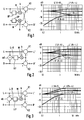
- each circuit has an input for a left signal L and another input for a right signal R. Accordingly, each modification circuit has an output for a modified left signal L ' and another output has a modified right signal R ' . Furthermore, each circuit contains a first and second combination device K1, K2, in which different signal components are combined with one another, as a rule added or subtracted, in order finally to form the modified output signal L ' or R ' . These modified signals are then each fed to at least one loudspeaker (not shown), and these must not be too close together.
- Filter circuits are included in all of the circuits of FIGS. 1 to 5.
- the lower ones Frequency components up to a few 100 Hz are available as mono signals and the directional dependence only affects the frequency components above. This takes into account the fact that low frequencies cannot be resolved by the human ear in any direction.
- the individual signal components that influence the right and left signal are thus high-pass filtered signals, so that the filter circuits operating in the forward direction are implemented by high-pass filters HP.
- the respective contribution of the individual signal components to the modification is controlled by multipliers M and weighting factors, which can be negative, positive and the amount greater than 1. In reality, the weighting factors move in relatively narrow areas, because otherwise the effects produced create a false sound impression.
- FIGS. 2 and 3 there is only one multiplier M, which effects the weighting by means of a supplied signal k.
- Fig. 1 there are two multipliers M, both of which are driven by the weighting factor k.
- the aim is to keep the frequency response as straight as possible after the modification, because otherwise the sound will be distorted.
- the overall impression of volume should not be changed either.
- the directional impression is amplified by subtracting part of the first and second signals L and R, which is determined by the weighting factor k and a high-pass filter HP, from the other signal R and L, respectively becomes.
- the frequency diagram on the left shows that this modification is ideal if either only a first signal L or only a second signal R is present.
- the known circuit example of FIG. 2 reinforces the directional impression by subtracting signal components with the same signal component, that is to say signals with a high sum component L + R, from the first and second signals L and R, as a result of which the differences in the first and second signals become more apparent.
- a difference signal L-R is finally formed from the first and second signals L and R by means of a subtractor sb and a signal component is formed therefrom by means of a high-pass filter HP and a weighting stage M, which adds to the first signal L. and from the second Signal R is subtracted.
- the difference between the first and second signals is increased by adding and subtracting the difference value, so that the modified signals L ' , R ' have an amplified directional effect at the output and thus enlarge the stereo base.
- the frequency response is very unfavorable.
- the invention teaches that a general circuit with which all variants can be realized can be accomplished by including further signal components in the respective modification, the influence of which is controlled by associated weighting factors.
- the individual signal components are also combined by means of combination devices, ie added or subtracted, in order finally to obtain a modified first and second signal L ' or R ' again.
- each modified signal is formed by three signal components.
- each signal component individually using a filter circuit and a weighting factor as required.
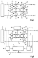
- the embodiment according to FIG. 4 already represents a simplification insofar as two signal components s2, s3 and s5, s6 are routed via a single filter circuit F2 and F4.
- a signal source q supplies a first and a second signal L, R at its output.
- the signal source q is not determined in more detail, it can also represent, for example, a multiple signal source with parallel outputs, the first and second signals being attributed to adjacent signals.
- the exemplary embodiments are limited to stereo signals, the first signal L corresponding to a left signal and the second signal R corresponding to a right signal. In these cases, the signal source q contains a decoder for stereo multiplex signals.
- the first signal L is fed to an input of a first combination device K1 by means of a first filter F1 and a first weighting device with a multiplier M1 as the first signal component s1.
- the associated weighting factor g is supplied to the first multiplier M1 as a data value or corresponds to a fixed position shift.
- the first signal L is also fed to the input of a second filter F2 and forms, by means of a second weighting device, a sixth signal component s6 which is fed to a second combination device K2, at the output of which the second modified signal R 'can be tapped.
- the weighting in the second weighting device effects a second multiplier M2, the weighting input of which is supplied with a second weighting factor k.
- the signal is passed through a third weighting device and reaches the first combination device K1 as second signal component s2.
- the weighting in the third weighting device effects a third multiplier M3, the weighting input of which is supplied with a third weighting factor ⁇ .
- a fourth, fifth and third signal component s4, s5, s3 are formed from the second signal R.
- a third or fourth filter F3, F4 corresponds to the first or the second filter F1, F2.
- the first, second and third multipliers M1, M2, M3 correspond to a fourth, fifth and a sixth multiplier M4, M5, M6, to which the first, second and third weighting factors g, k and ⁇ are supplied.
- the third and sixth signal components s3, s6 are routed to a subtrahead input of the first and second combination devices K1, K2. The subtrahend inputs can be avoided if the associated weighting factors are changed in the sign.
- FIG. 5 shows another exemplary embodiment of the invention which contains the circuit of FIG. 4 in a simplified form.
- the circuit contains regulating devices, b1, b2, r and control devices st for regulating and / or specifying the weighting factors.
- the embodiment of the circuit according to FIG. 5 is oriented even more towards the processing of audio signals than the more general circuit from FIG. 4.
- the signal source q provides the first and second signals L, R a left and right signal.
- the first and fourth signal components s1, s4 are neither filtered nor weighted but correspond directly to the first and second signals L and R.
- the first signal L is used to form the sixth signal component s6, which is fed to the subtrahend input of the second combination device K2 .
- the third signal component s3, which is fed to the subtrahend input of the first combination device K1 is formed from the second signal R by means of a high-pass filter HP and the same weighting factor k.
- the second weighting factor k is controlled by the control device st, which thus influences the level of the desired effect and thus the stereo base width.
- high-pass filters HP whose cut-off frequency is greater than 300 Hz and typically, are used to form the second, third, fifth and sixth signal components s2, s3, s5, s6 is at 700 Hz. It can be seen from the frequency diagrams of FIGS. 1 to 3 that the range of the signal increases or decreases is changed via the cut-off frequency, which has an effect on the auditory impression in the case of mixed signals.
- the second and fifth signal components s2, s5 are formed from the high-pass filtered first and second signals, respectively, by changing the size of the signal by means of the third weighting factor ⁇ .
- the value of the third weighting factor ⁇ can now be used to set not only the properties of the known circuits from FIGS. 1 to 3, but also any intermediate stages, which enables optimum signal adaptation.
- a weighting factor ⁇ which is approximately between 0.4 and 0.5
- a frequency response is set which corresponds to the frequency response of FIG. 2 and is optimal for mixed signals.
- the third weighting factor ⁇ can also be negative in order to reduce the signal boost for unspecific signals in the upper frequency range.
- the third weighting factor ⁇ can be set in different ways. Either as a fixed value via the control device st - this is shown in FIG. 5 by a dashed connection. However, the third weighting factor ⁇ can also be controlled adaptively by the signal properties themselves, which are determined, for example, by means of a first evaluation device b1 from the left and right signals L, R. In the simplest case, the mono or difference signal component is determined via adders or subtractors. Individual frequency ranges can be treated separately or specially weighted by means of individual filters with which the physiological hearing sensitivity is simulated, for example. This corresponds to an adaptive control of the weighting factor ⁇ , which is shown schematically in FIG. 5 by the dashed line at the output of the first evaluation device b1.
- the outputs of the first and second evaluation devices b1, b2 can be connected to a control device r, the output of which controls the level of the weighting factors.
- the control device r can be used, in particular, to ensure that the volume impression does not change during the modification, regardless of the respective effect control. If the control device r is to take into account the volume impression in the entire frequency range or in individual frequency ranges, then the first and second evaluation devices b1, b2 must determine, among other things, performance-related data from the signals at the input and output of the modification circuit. In the exemplary embodiment of FIG. 5, the output of the control device r controls the third weighting factor ⁇ .
- the proportion of the first or second signal L, R can be controlled via the first weighting factor g.
- the first and third filters F1, F3 can be connected through or can be implemented by an all-pass.
- the time equalizations required for digital circuits are, as usual, not shown in the individual circuit examples. It is again pointed out that the invention and the associated exemplary embodiments are in no way limited to the processing of stereo signals, but that the adaptive effect control is advantageous for many other signals.
Landscapes
- Physics & Mathematics (AREA)
- Engineering & Computer Science (AREA)
- Acoustics & Sound (AREA)
- Signal Processing (AREA)
- Stereophonic System (AREA)
- Tone Control, Compression And Expansion, Limiting Amplitude (AREA)
Priority Applications (5)
| Application Number | Priority Date | Filing Date | Title |
|---|---|---|---|
| DE59509187T DE59509187D1 (de) | 1995-11-25 | 1995-11-25 | Signalmodifikationsschaltung |
| EP95118595A EP0776144B1 (fr) | 1995-11-25 | 1995-11-25 | Circuit pour la modification d'un signal |
| JP8311836A JPH09191499A (ja) | 1995-11-25 | 1996-11-22 | 信号修正回路 |
| US08/754,144 US5822437A (en) | 1995-11-25 | 1996-11-22 | Signal modification circuit |
| KR1019960056382A KR100424520B1 (ko) | 1995-11-25 | 1996-11-22 | 신호변경회로및방법 |
Applications Claiming Priority (1)
| Application Number | Priority Date | Filing Date | Title |
|---|---|---|---|
| EP95118595A EP0776144B1 (fr) | 1995-11-25 | 1995-11-25 | Circuit pour la modification d'un signal |
Publications (2)
| Publication Number | Publication Date |
|---|---|
| EP0776144A1 true EP0776144A1 (fr) | 1997-05-28 |
| EP0776144B1 EP0776144B1 (fr) | 2001-04-11 |
Family
ID=8219836
Family Applications (1)
| Application Number | Title | Priority Date | Filing Date |
|---|---|---|---|
| EP95118595A Expired - Lifetime EP0776144B1 (fr) | 1995-11-25 | 1995-11-25 | Circuit pour la modification d'un signal |
Country Status (5)
| Country | Link |
|---|---|
| US (1) | US5822437A (fr) |
| EP (1) | EP0776144B1 (fr) |
| JP (1) | JPH09191499A (fr) |
| KR (1) | KR100424520B1 (fr) |
| DE (1) | DE59509187D1 (fr) |
Families Citing this family (10)
| Publication number | Priority date | Publication date | Assignee | Title |
|---|---|---|---|---|
| FI106355B (fi) * | 1998-05-07 | 2001-01-15 | Nokia Display Products Oy | Menetelmä ja laite virtuaalisen äänilähteen syntetisoimiseksi |
| US7136493B2 (en) * | 2000-06-28 | 2006-11-14 | Peavey Electronics Corporation | Sub-harmonic generator and stereo expansion processor |
| US7242779B2 (en) * | 2002-05-30 | 2007-07-10 | Peavey Electronics Corporation | Methods and apparatus for sub-harmonic generation, stereo expansion and distortion |
| JP4509686B2 (ja) * | 2004-07-29 | 2010-07-21 | 新日本無線株式会社 | 音響信号処理方法および装置 |
| JP2009065436A (ja) * | 2007-09-06 | 2009-03-26 | New Japan Radio Co Ltd | ステレオ再生装置 |
| US8335331B2 (en) * | 2008-01-18 | 2012-12-18 | Microsoft Corporation | Multichannel sound rendering via virtualization in a stereo loudspeaker system |
| US8577065B2 (en) * | 2009-06-12 | 2013-11-05 | Conexant Systems, Inc. | Systems and methods for creating immersion surround sound and virtual speakers effects |
| US20150036828A1 (en) * | 2013-05-08 | 2015-02-05 | Max Sound Corporation | Internet audio software method |
| US20140362996A1 (en) * | 2013-05-08 | 2014-12-11 | Max Sound Corporation | Stereo soundfield expander |
| US20150036826A1 (en) * | 2013-05-08 | 2015-02-05 | Max Sound Corporation | Stereo expander method |
Citations (7)
| Publication number | Priority date | Publication date | Assignee | Title |
|---|---|---|---|---|
| GB2180727A (en) * | 1985-09-12 | 1987-04-01 | Sgs Microelettronica Spa | Non-recursive system for expanding the stereo base of stereophonic acoustic diffusion apparatus |
| WO1990000851A1 (fr) * | 1988-07-08 | 1990-01-25 | Adaptive Control Limited | Ameliorations apportees a des systemes de reproduction du son |
| EP0476790A2 (fr) * | 1986-03-27 | 1992-03-25 | SRS LABS, Inc. | Système de rehaussement d'effet stéréo |
| US5136650A (en) * | 1991-01-09 | 1992-08-04 | Lexicon, Inc. | Sound reproduction |
| EP0615399A1 (fr) * | 1993-03-09 | 1994-09-14 | Matsushita Electric Industrial Co., Ltd. | Système de commande de champ sonore |
| EP0637191A2 (fr) * | 1993-07-30 | 1995-02-01 | Victor Company Of Japan, Ltd. | Appareil de traitement d'un signal d'effet spatial |
| US5420929A (en) * | 1992-05-26 | 1995-05-30 | Ford Motor Company | Signal processor for sound image enhancement |
Family Cites Families (14)
| Publication number | Priority date | Publication date | Assignee | Title |
|---|---|---|---|---|
| KR880005354A (ko) * | 1986-10-08 | 1988-06-28 | 나까무라 겐조 | 전자 작동기 |
| JPH0435499A (ja) * | 1990-05-31 | 1992-02-06 | Sony Corp | 音響付加回路 |
| DE4028447A1 (de) * | 1990-09-07 | 1992-03-12 | Teves Gmbh Alfred | Elektromagnetventil fuer hydraulische bremsanlagen mit schlupfregelung |
| DE4030424A1 (de) * | 1990-09-26 | 1992-04-02 | Bosch Gmbh Robert | Druckbegrenzungsventil, insbesondere fuer hydraulische kraftfahrzeug-bremsanlagen |
| DE4030971A1 (de) * | 1990-10-01 | 1992-04-02 | Bosch Gmbh Robert | Elektromagnetbetaetigtes ventil |
| DE4103365A1 (de) * | 1991-02-05 | 1992-08-13 | Teves Metallwaren Alfred | Drucksteuerventil |
| DE9102383U1 (de) * | 1991-02-28 | 1991-05-16 | Türk & Hillinger GmbH, 78532 Tuttlingen | Axialer Schraubanschluß für elektrische Rohrheizkörper |
| DE9107436U1 (de) * | 1991-06-17 | 1991-08-22 | Binder Magnete GmbH, 7730 Villingen-Schwenningen | Elektromagnetventil mit Druckmittel beöltem Magnetsystem |
| DE4129638C2 (de) * | 1991-09-06 | 2002-01-10 | Bosch Gmbh Robert | Hydraulisches Sitzventil |
| DE4135062A1 (de) * | 1991-10-24 | 1993-04-29 | Bosch Gmbh Robert | Verfahren zum beschleunigen des bremseneingriffs im antriebsschlupfregelbetrieb und hydraulische bremsanlage zur durchfuehrung des verfahrens |
| DE4141546C2 (de) * | 1991-12-17 | 2002-02-14 | Continental Teves Ag & Co Ohg | Elektromagnetventil, insbesondere für hydraulische Bremsanlagen mit Schlupfregelung |
| DE4236047A1 (de) * | 1992-10-24 | 1994-04-28 | Teves Gmbh Alfred | Bremsanlage mit Blockierschutz- und/oder Antriebsschlupfregelung |
| EP0691050B1 (fr) * | 1993-03-24 | 1996-12-18 | Blaupunkt-Werke GmbH | Circuit pour la derivation de signaux de masquage de signaux audio |
| US5440638A (en) * | 1993-09-03 | 1995-08-08 | Q Sound Ltd. | Stereo enhancement system |
-
1995
- 1995-11-25 DE DE59509187T patent/DE59509187D1/de not_active Expired - Fee Related
- 1995-11-25 EP EP95118595A patent/EP0776144B1/fr not_active Expired - Lifetime
-
1996
- 1996-11-22 US US08/754,144 patent/US5822437A/en not_active Expired - Lifetime
- 1996-11-22 KR KR1019960056382A patent/KR100424520B1/ko not_active Expired - Fee Related
- 1996-11-22 JP JP8311836A patent/JPH09191499A/ja active Pending
Patent Citations (7)
| Publication number | Priority date | Publication date | Assignee | Title |
|---|---|---|---|---|
| GB2180727A (en) * | 1985-09-12 | 1987-04-01 | Sgs Microelettronica Spa | Non-recursive system for expanding the stereo base of stereophonic acoustic diffusion apparatus |
| EP0476790A2 (fr) * | 1986-03-27 | 1992-03-25 | SRS LABS, Inc. | Système de rehaussement d'effet stéréo |
| WO1990000851A1 (fr) * | 1988-07-08 | 1990-01-25 | Adaptive Control Limited | Ameliorations apportees a des systemes de reproduction du son |
| US5136650A (en) * | 1991-01-09 | 1992-08-04 | Lexicon, Inc. | Sound reproduction |
| US5420929A (en) * | 1992-05-26 | 1995-05-30 | Ford Motor Company | Signal processor for sound image enhancement |
| EP0615399A1 (fr) * | 1993-03-09 | 1994-09-14 | Matsushita Electric Industrial Co., Ltd. | Système de commande de champ sonore |
| EP0637191A2 (fr) * | 1993-07-30 | 1995-02-01 | Victor Company Of Japan, Ltd. | Appareil de traitement d'un signal d'effet spatial |
Also Published As
| Publication number | Publication date |
|---|---|
| KR970032266A (ko) | 1997-06-26 |
| KR100424520B1 (ko) | 2004-06-18 |
| EP0776144B1 (fr) | 2001-04-11 |
| DE59509187D1 (de) | 2001-05-17 |
| JPH09191499A (ja) | 1997-07-22 |
| US5822437A (en) | 1998-10-13 |
Similar Documents
| Publication | Publication Date | Title |
|---|---|---|
| DE68928033T2 (de) | Stereosynthesizer und entsprechendes verfahren | |
| DE2616762C2 (de) | Einrichtung zur Aufweitung eines stereophonen Klangbildes | |
| DE69433258T2 (de) | Raumklangsignalverarbeitungsvorrichtung | |
| DE19715498B4 (de) | Stereoklangbildverbesserungsvorrichtungen und -verfahren unter Verwendung von Tabellen | |
| DE3752052T2 (de) | Stereoeffektverbesserungssystem | |
| EP1912471B1 (fr) | Traitement d'un signal d'entrée dans une prothése auditive | |
| EP0808076B1 (fr) | Système acoustique à effet spatial | |
| DE2720984B2 (fr) | ||
| DE3519644A1 (de) | Verfahren und vorrichtung zur tonwiedergabe mit einem realistischen raumklangeindruck | |
| DE4136022A1 (de) | Vorrichtung zum ausweiten und steuern von schallfeldern | |
| DE69533211T2 (de) | Signalkombinationsschaltung für stereophonische Wiedergabe mit Quersignalkoppelung | |
| DE2627437C3 (de) | Quadrophoniesystem für kopfbezogene Vierkanalstereophonie mit Lautsprecherwiedergabe | |
| DE112012006457B4 (de) | Frequenzcharakteristikmodifikationsgerät | |
| DE69227091T2 (de) | Schaltung zur Mischung und Verdoppelung von niedrigen Tonfrequenzen | |
| DE2512287A1 (de) | Tonwiedergabesystem | |
| DE3040896C2 (de) | Schaltungsanordnung zur Erzeugung und Aufbereitung stereophoner Signale aus einem monophonen Signal | |
| EP2939445B1 (fr) | Production de signaux audio 3d | |
| EP0825800A2 (fr) | Méthode et appareil pour générer des signaux multi-audio d'un signal audio-mono | |
| EP0776144B1 (fr) | Circuit pour la modification d'un signal | |
| DE69528550T2 (de) | Erzeugung eines gemeinsamen Basssignales | |
| DE3142157C2 (fr) | ||
| DE69707847T2 (de) | Vorrichtung zur vearbeitung von stereosignalen | |
| EP1104221B1 (fr) | Dispositif de sonorisation | |
| DE19900961A1 (de) | Verfahren und Vorrichtung zur Wiedergabe von Mehrkanaltonsignalen | |
| DE2129673C3 (de) | Mehrrichtungs-Tonsystem, Dekodierer und Kodierer hierfür |
Legal Events
| Date | Code | Title | Description |
|---|---|---|---|
| PUAI | Public reference made under article 153(3) epc to a published international application that has entered the european phase |
Free format text: ORIGINAL CODE: 0009012 |
|
| AK | Designated contracting states |
Kind code of ref document: A1 Designated state(s): DE FR GB IT NL |
|
| 17P | Request for examination filed |
Effective date: 19971128 |
|
| RAP1 | Party data changed (applicant data changed or rights of an application transferred) |
Owner name: MICRONAS INTERMETALL GMBH |
|
| 17Q | First examination report despatched |
Effective date: 19990323 |
|
| RAP1 | Party data changed (applicant data changed or rights of an application transferred) |
Owner name: MICRONAS GMBH |
|
| GRAG | Despatch of communication of intention to grant |
Free format text: ORIGINAL CODE: EPIDOS AGRA |
|
| GRAG | Despatch of communication of intention to grant |
Free format text: ORIGINAL CODE: EPIDOS AGRA |
|
| GRAH | Despatch of communication of intention to grant a patent |
Free format text: ORIGINAL CODE: EPIDOS IGRA |
|
| GRAH | Despatch of communication of intention to grant a patent |
Free format text: ORIGINAL CODE: EPIDOS IGRA |
|
| GRAA | (expected) grant |
Free format text: ORIGINAL CODE: 0009210 |
|
| AK | Designated contracting states |
Kind code of ref document: B1 Designated state(s): DE FR GB IT NL |
|
| GBT | Gb: translation of ep patent filed (gb section 77(6)(a)/1977) |
Effective date: 20010425 |
|
| REF | Corresponds to: |
Ref document number: 59509187 Country of ref document: DE Date of ref document: 20010517 |
|
| ITF | It: translation for a ep patent filed | ||
| ET | Fr: translation filed | ||
| REG | Reference to a national code |
Ref country code: GB Ref legal event code: IF02 |
|
| PLBE | No opposition filed within time limit |
Free format text: ORIGINAL CODE: 0009261 |
|
| STAA | Information on the status of an ep patent application or granted ep patent |
Free format text: STATUS: NO OPPOSITION FILED WITHIN TIME LIMIT |
|
| 26N | No opposition filed | ||
| PGFP | Annual fee paid to national office [announced via postgrant information from national office to epo] |
Ref country code: NL Payment date: 20071124 Year of fee payment: 13 |
|
| PGFP | Annual fee paid to national office [announced via postgrant information from national office to epo] |
Ref country code: IT Payment date: 20071128 Year of fee payment: 13 |
|
| PGFP | Annual fee paid to national office [announced via postgrant information from national office to epo] |
Ref country code: GB Payment date: 20071128 Year of fee payment: 13 Ref country code: FR Payment date: 20071119 Year of fee payment: 13 |
|
| PGFP | Annual fee paid to national office [announced via postgrant information from national office to epo] |
Ref country code: DE Payment date: 20071221 Year of fee payment: 13 |
|
| GBPC | Gb: european patent ceased through non-payment of renewal fee |
Effective date: 20081125 |
|
| PG25 | Lapsed in a contracting state [announced via postgrant information from national office to epo] |
Ref country code: NL Free format text: LAPSE BECAUSE OF NON-PAYMENT OF DUE FEES Effective date: 20090601 |
|
| NLV4 | Nl: lapsed or anulled due to non-payment of the annual fee |
Effective date: 20090601 |
|
| PG25 | Lapsed in a contracting state [announced via postgrant information from national office to epo] |
Ref country code: IT Free format text: LAPSE BECAUSE OF NON-PAYMENT OF DUE FEES Effective date: 20081125 |
|
| REG | Reference to a national code |
Ref country code: FR Ref legal event code: ST Effective date: 20090731 |
|
| PG25 | Lapsed in a contracting state [announced via postgrant information from national office to epo] |
Ref country code: DE Free format text: LAPSE BECAUSE OF NON-PAYMENT OF DUE FEES Effective date: 20090603 |
|
| PG25 | Lapsed in a contracting state [announced via postgrant information from national office to epo] |
Ref country code: GB Free format text: LAPSE BECAUSE OF NON-PAYMENT OF DUE FEES Effective date: 20081125 |
|
| PG25 | Lapsed in a contracting state [announced via postgrant information from national office to epo] |
Ref country code: FR Free format text: LAPSE BECAUSE OF NON-PAYMENT OF DUE FEES Effective date: 20081130 |