EP0776459B1 - Observations sous une surface d'eau agitee - Google Patents
Observations sous une surface d'eau agitee Download PDFInfo
- Publication number
- EP0776459B1 EP0776459B1 EP95927061A EP95927061A EP0776459B1 EP 0776459 B1 EP0776459 B1 EP 0776459B1 EP 95927061 A EP95927061 A EP 95927061A EP 95927061 A EP95927061 A EP 95927061A EP 0776459 B1 EP0776459 B1 EP 0776459B1
- Authority
- EP
- European Patent Office
- Prior art keywords
- water
- representation
- areas
- slope
- intensity
- Prior art date
- Legal status (The legal status is an assumption and is not a legal conclusion. Google has not performed a legal analysis and makes no representation as to the accuracy of the status listed.)
- Expired - Lifetime
Links
Images


Classifications
-
- G—PHYSICS
- G01—MEASURING; TESTING
- G01C—MEASURING DISTANCES, LEVELS OR BEARINGS; SURVEYING; NAVIGATION; GYROSCOPIC INSTRUMENTS; PHOTOGRAMMETRY OR VIDEOGRAMMETRY
- G01C13/00—Surveying specially adapted to open water, e.g. sea, lake, river or canal
- G01C13/002—Measuring the movement of open water
- G01C13/004—Measuring the movement of open water vertical movement
Definitions
- This invention relates generally to observations of the environment that can be made underwater; and more particularly to use of observations from below a rough water surface to determine and use details of the water surface waves ⁇ and, based on such details, various above-surface data.
- underwater craft are already deployed around the world continuously in considerable numbers. They are thus potentially positioned to collect a large amount of useful local microdata about water surfaces ⁇ and the space above them ⁇ that later could be beneficially employed by correlation with other information (for instance, satellite radar pictures) to enhance the interpretation of that other information as well as operations of the craft. Observational limitations, however, deter effective use of this great potential resource.
- submerged underwater apparatus is severely limited in ability to detect conditions at or above the surface, and even ability to receive data communications from above the surface.
- Light and other electromagnetic radiation are strongly attenuated in passing through water, particularly ocean water; acoustic transmission too is limited in range, and awkward for both observation and data transmission.
- the electromagnetic spectrum provides practical means of observation and communication only in two wavelength ranges: in the blue-green part of the visible spectrum (and even there over only very short distances, such as a few hundred meters) and at so-called "extra low frequencies” (ELF) in the radio spectrum.
- ELF extra low frequencies
- High-bandwidth transmissions from above the surface are not receivable by equipment at normal operating depths of, for example, thirty meters or more.
- signals from a blue-green laser beacon projected, for example, from a satellite
- Underwater equipment would not know in which direction to look, at each instant, to see such signals. Most of the energy in acoustic messages from above the water would be reflected by the surface.
- a second is in the area of satellite-based data collection to analyze conditions of the ocean surface.
- a third earlier area relates to radar processing.
- Cox and Munk neither proposed nor suggested any effort to dissect the wave-formed remapping of the sky to learn or use the orientations of, for example, individual waves. They simply performed a mathematical reversal of the overall remapping to learn something about the as-ensemble properties of the water surface as a distorting/reimaging element.
- US-A-4,988,885 discloses a single optical wave measurement sensor which can be submerged below an irregular water surface and which can observe, through the water, the light intensity of a single area of the irregular water surface defined by the field of view of the sensor. Among others, there are calculated wave heights and wave amplitudes.
- the present invention refers to a method and an apparatus for obtaining and using an above-water-representation based upon optical observations made from below the surface according to claims 1 and 25, respectively.
- Preferred embodiments are subject matter of dependent claims.
- the invention is a method for obtaining and using information about an irregular water surface.
- the method obtains such information based upon optical observations made from a distance below the surface.
- a distance encompasses distances as short as perhaps five or ten meters, though a distance of roughly thirty to sixty meters is considered ideal. It is also intended to encompass distances as long as perhaps one hundred to three hundred meters or more, depending on local clarity of the water.
- the method includes the step of, from below the water surface, observing through the water directly the respective light intensity of each of a large number of areas of the irregular water surface.
- through the water directly means to distinguish observations made through air that is held within a chamber ⁇ as for example through an air-filled tube.
- the areas mentioned above may be individual pixels of an image-collecting system, for example pixels defined by a fixed or scanning array of charge-coupled detectors (CCDs), or defined as positions along successive line scans in a raster system such as typically used in video cameras.
- the "areas" may be groupings of such pixels: either fixed arbitrary groupings, or groupings based on instantaneously observed relationships between the observed intensities, or groupings defined in other ways such as will be suggested by the remainder of this description of my invention.
- the method of this first aspect of the invention also includes the step of, based on the observed light intensity for each of the areas, estimating surface-slope magnitudes and orientations for at least some of the areas. Various techniques for making such estimates will be described in detail shortly.
- This method also includes the steps of assembling the light-intensity information, at least for selected areas, to form a quantitative representation of the irregular water surface; and applying the water-surface representation to control a physical process that is one of these:
- the slope-estimating step include the substep of correlating at least one known illumination pattern above the surface with light intensity of some of the areas observed from below the surface.
- Such a known illumination pattern preferably includes direct illumination from an astronomical object in a known position, and still more preferably such an object is the sun or the moon.
- the position of the sun and moon can be known very precisely to operators of underwater craft; and automatic equipment can be store and refer to such positional information fcr purposes of my invention.
- the slope-estimating step also include a substep of finding bounds for slopes of some areas, other than those areas where the known illumination pattern is seen, based upon a priori knowledge of physical phenomena.
- the slope-estimating step include coordinating the correlating and bound-determining substeps to estimate slopes for still other areas.
- the slope-estimating step include coordinating the correlating and the bound-determining substeps to predict future slopes; and coordinating the predicted future slopes with later correlating and bound-determining substeps to refine the slope-estimating step for still-later observations.
- this number be greater than 10,000 ⁇ and still more preferably on the order of 250,000.
- my invention is a novel method for collecting above-water data, when the water surface is irregular.
- the method is based upon optical observations made from a distance below the surface.
- the method includes the steps of, from below the water surface, preliminarily observing through the water directly the respective light intensity of each of a large number of areas of the irregular water surface; and, based on the observed light intensity for each of the areas, preliminarily estimating surface-slope magnitudes and orientations for at least some of the areas.
- the method of this second aspect of the invention includes the step of, based upon the observed light intensities and on the slope-magnitude and slope-orientation estimates, predicting a time and a limited water-surface region at which conditions will be particularly favorable for collecting above-water data. Examples of such conditions and corresponding data will be presented shortly.
- the method now under discussion also includes the step of, after the predicting step, applying the predictions to control selective observation, through water directly, of the respective light intensity of each of a large number of areas of the irregular surface in the predicted region at the predicted time.
- These selective observations are not necessarily exclusive of all other areas, but at the least emphasize collection of information from the predicted region at the predicted time relative to other areas and/or times.
- an optical system may zoom in toward a predicted region shortly before the predicted time, and zoom back out shortly after ⁇ in such a way that even at the predicted time information is collected from some areas near but outside the predicted region.
- Such adjacency information may be used, if desired, for example to help keep the information from the predicted region in register with information from other areas.
- the method in this second aspect of my invention include the added step of, based on the selectively observed light intensity for each of the areas at the predicted region and time, estimating corresponding surface-slope magnitudes and orientations for at least some of the areas at the predicted region and time.
- I also prefer to include in this method other steps, for example the step of associating the selectively observed respective intensity with respective above-water elevation and azimuth, for the at least some areas at the predicted region and time, through use of the estimated corresponding surface-slope magnitudes and orientations for the at least some areas at the predicted region and time.
- This step will later be recognized as analogous to an associating step in the third aspect of my invention ⁇ but performed with respect to only the selectively observed intensities.
- the predicted time and region be identified with formation of a relatively tall wave.
- the portion of the above-water scene for which data-collecting conditions will be particularly favorable is at a relatively low angle of elevation above the horizon ⁇ a useful region, since it corresponds to relatively very remote objects.
- the predicted time and region be identified with formation of a relatively very smooth surface area.
- data for a portion of the above-water space may be acquired with minimal necessity for unscrambling, and only the necessity ⁇ if position of that portion is important to the application at hand ⁇ of correcting for deflection of the incoming information by refraction at the smooth surface.
- the invention is a method for obtaining and using, when the water surface is irregular, above-water-surface information ⁇ rather than information about the surface itself as in the first aspect of the invention discussed already. This method too, however, is based upon optical observations made from a distance below the surface.
- this method includes the steps of, from below the water surface, observing through the water directly the respective light intensity of each of a large number of areas of the irregular water surface; and, based on the observed light intensity for each of the areas, estimating surface-slope magnitudes and orientations for at least some of the areas.
- this method includes the step of associating the respective light intensity with respective above-water elevation and azimuth, for the same "at least some" areas.
- This associating step is performed straightforwardly through use of the estimated surface-slope magnitudes and orientations, applying the well-known Snell's Law to account for the deflection of light paths by refraction.
- each of the "at least some” areas is observed along a well-defined light path through the water directly, and has an estimated slope magnitude and orientation.
- the angle between the light path and each surface-area normal considered together with Snell's Law, establishes the deflection undergone by incoming light that passes through that area.
- This deflection considered together with the light path through the water, establishes an estimated path through the air approaching the same surrace area.
- the elevation and azimuth or this path are taken as the above-water elevation and azimuth with which the corresponding light intensity, observed through the same surface area, should be associated in the "associating" step.
- the method of this third phase or aspect of the invention also includes the step of assembling the light-intensity information as a function of above-water elevation and azimuth, at least for selected areas, to form an above-water representation ⁇ typically a data array.
- this "assembling" step is a reassembling step, since the above-water information may be regarded as having been dis assembled or fragmented in passage through the many water-surface areas or facets, seemingly oriented at random. As -will be seen, the orientations are not truly random, and in the practice of my invention important relationships between the orientations of nearby areas can be found and used to help form the slope estimates mentioned earlier.
- my invention seeks to assign or associate near-original elevation and azimuth values to the light intensities received through each of many small water-surface areas. The invention then uses these associations to form the above-water representation.
- Another step of the third aspect or method of my invention is applying the representation to control a physical process.
- the process is one of these:
- the invention in this third aspect enables a usable representation of the above-water space to be obtained from underwater.
- a representation may be most intuitively understood as having the form of a visible image ⁇ but other forms, concentrating on specific desired data relationships rather than visible features as such, will be preferred instead for some tasks or applications.
- the intensity-associating step comprise the substeps of determining an observation angle for each of the areas; and applying Snell's law to the determined observation angles and estimated slopes.
- the intensity-associating step further include the substeps of determining the observation depth and then allowing for intensity attenuation due to propagation distance through water for each of the at least some areas.
- preferred embodiments of my invention provide apparatus for obtaining and using an above-water-surface representation, when the water surface is irregular, based upon optical observations made from a distance below the surface. It is here understood that the irregular surface has the effect of scrambling what is above the water as viewed from the "distance" below the surface.
- the apparatus includes some means for disposition at a distance below the surface to receive light from the surface, through the water directly, and in response generate signals corresponding to intensity of the received light as a function of reception angle.
- These means operate by optical sensing, and for purposes of generality and breadth in description of the invention will be here called simply the "optical sensor means”.
- the apparatus includes some means for processing the signals to analyze and correct for at least part of the scrambling effect of the surface and so form a representation of at least part of what is above the water.
- These means include at least one programmed processor, and ⁇ here too for breadth and generality ⁇ will be called the "programmed processor means” or simply the “processor means”.
- apparatus of this fourth aspect of the invention includes some means for applying the representation to control a physical process. These means, again for generality and breadth, I shall call the "utilization means”.
- this fourth aspect of the invention as thus broadly couched offers many advantages and benefits including those of the third aspect of the invention ⁇ and others as well, since the utilization means here may apply the representation to control physical processes other than the enumerated third-aspect processes and their equivalents.
- the senor means include some means for generating electronic signals, and the processor means comprise at least one electronic processor.
- the processor means comprise at least one electronic processor.
- My invention is amenable, however, to practice with one or more other types of processors ⁇ such as for instance an optical processor.
- the senor means comprise means for generating digital signals
- the processor means comprise at least one digital processor.
- my invention may be practiced using one or more other types of processors ⁇ as, for example, analog processors.
- the processor means include some means for forming a first signal matrix corresponding to intensity of received light as a function of reception angle; and some means for analyzing the first signal matrix to estimate surface-slope magnitudes and orientations for a large number of areas of the irregular water surface.
- the processor means include some means for interpreting the first signal matrix, through use of the estimated surface-slope magnitudes and orientations, to form a second signal matrix corresponding to intensity of received light as a function of elevation and azimuth of what is above the water, at least for selected areas.
- utilization means in this fourth aspect of my invention may take any of a great variety of forms, I prefer that the utilization means include at least one of these:
- the apparatus of my invention further include movable underwater equipment carrying the already-mentioned apparatus, in position to receive light from the water surface at least when the equipment is at a distance below the water surface.
- the utilization means preferably comprise means for applying the representation of the above-water scene to control operations of the equipment.
- the representation-applying means control one or more of these operations: steering the equipment in any of three dimensions, and receiving messages from at least one discrete source above the surface.
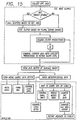
- Fig. 15 summarizes the methodologies of my invention, and is intended to be ⁇ in the light of the descriptions and explanations presented in this text ⁇ self explanatory to those skilled in art.
- I have simulated, and tested the simulation of, my invention in a simplified and preliminary form, not a final or practically usable form.
- the height, frequency, degree of coherence and direction of water waves 11, for instance, will inform meteorologists of the speed and consistency of wind 13 above the surface.
- Small-scale surface disruptions indicate precipitation 14 reaching the water surface 11, and the character of such disruptions reveals the size and density of the precipitation 14.
- all the above-described information can be compared with simultaneously collected information from airborne or orbiting equipment 23, for example radar equipment or optical cameras, to essentially calibrate such high-altitude data gathering 24.
- the result ⁇ previously mentioned in terms of "characterizing" the radar data 24 ⁇ will be much more meaningful radar information, and much more meaningful use of that information as for example in live weather reporting 25 to the general public 26.
- Preferred embodiments of the first and fourth aspects of the invention may include either a fixed or movable underwater installation 21.
- the emphasis is on collecting information about the environment, as for example in remote ocean areas (rather than operation of whatever equipment is holding the apparatus of the invention); such information may be transmitted 31 to shore facilities 32 by electrical or optical data cables 33.
- the installation 21b may be placed on the ocean bottom 34; in deeper zones a bottom-tethered installation 21t may be used instead. Either arrangement protects the installation from waves 11 and weather 13/14, and avoids interaction with surface craft.
- the sensor system may collect 35 information through generally 60° to 65° about vertical (that is, generally over a total 120° to 130° cone), but for environmental reporting a narrower collection angle may suffice since the intermediate object is simply to learn the condition of the water surface 11. This condition may be represented quite adequately by a smaller sampling of the surface.
- Cables 73 (Fig. 11) transmit 74 the collected information to a data processor 75, which first develops a dynamic estimate of water-surface slopes and then, by analyzing that estimate, derives somewhat more abstract properties of the surface waves, and completes a data representation of the surface or what is above.
- the representation itself may be simply a data array within a processing system 75, or in an associated data-storage or data-recording system 76, that is part of the apparatus of the fourth aspect of my invention.
- the data array may be in volatile memory in the processing or storage system 75, 76.
- nonvolatile memory 76 may take the form of, for example, digital data tape, computer disc, videotape, photography, and memory cache.
- the practice of the invention may include using the wind-direction and -speed information to help make decisions about small-craft 17 (Fig. 1) or other equipment movements, and implementing such movements according to the decisions thus-made.
- this part of the practice of my invention may be implemented through a shore facility 32, with human participation at such facility as desired ⁇ or alternatively the data acquired may be simply broadcast 16 (if necessary) for direct evaluation and use by operators of the equipment 17 to be moved.
- one type of equipment whose movements may be optimized by using my invention is an acoustic receiver array 28 ⁇ typically floating lightweight equipment extended along the ocean surface 11.
- Such listening devices 28, used for a various purposes, are adversely sensitive to pickup of noise from the wind 13.
- the senor 22 may be, as shown, an assemblage of two or more spaced-apart arrays 29 of charge-coupled detectors (CCDs). Each array 29 should be an unscanned two-dimensional array.
- CCDs charge-coupled detectors
- Each one of the two or more arrays 29 is in effect a complete CCD camera, and is advantageously focused on the ocean surface 11 by suitable lens means 71 (Fig. 11), so that each sensor element (e. g. , each single CCD) within each array 29 receives light from a respective small area of the water surface 11.
- the terms "array”, “sensor array” and “camera” are interchangeable.
- the two (or more) arrays 29 are both focused on essentially a common overall surface region, though some peripheral nonoverlap may generally occur. The reason for using plural arrays will become more clear momentarily.
- I first use this equipment to estimate certain characteristics of the ocean's surface 11.
- I estimate the magnitude and orientation of the ocean slopes ⁇ using a combination of three techniques.
- coherence is meant the relative extent of correlation between the phases of two waves, but for present purposes the term can be understood as simply a measure of the usefulness of the data produced in the slope-estimating stage.
- Fig. 9 shows special conditions whose development can be detected, and which thereby can be predicted, with the surface wave analysis discussed above. It will be understood that such use of the principles of my invention is not limited to the two examples given.
- One of these conditions is a momentarily existing relatively smooth region 11' of the surface 11. Such a region 11' may allow useful direct but momentary viewing of what is above the water.
- the wave analysis of my invention can predict the random occurrence of such regions 11'. Then when they do occur, to enhance utilization of this region 11' the data-collection resources of my invention can be concentrated into a much narrower (in two dimensions) angular range 54 that corresponds generally to the extent of the anticipated region 11'.
- One way of customizing data collection for this purpose is adjustment 72 (Fig. 11) of the lens means 71.
- the resulting narrower viewing trajectory 54 within the water corresponds above the surface 11 to a different line or cone 55 of sight ⁇ which is deflected by refraction, relative to the undersea path 54.
- this special viewing condition occurs whether anticipated or not.
- some relatively small fraction of the data collected even through continuing operation of my invention in its regular angular receiving range 35 will include usable information about the low objects 15' just mentioned.
- the opportunity is enhanced, however, by using data obtained through operation of my invention over its regular receiving range 35, to predict the tall wave 11". Then, for the duration of the tall wave 11", data collection is concentrated in the much smaller (in two dimensions) angular range 56 where the wave 11" is expected. The result may be improved detail in the low-angle information.
- the surface-wave estimates also enable very straightforward construction of an above-surface data-array representation. To accomplish this, rays reaching an individual sensor element are traced back, first, from the sensor to a small area of the ocean surface and second, from that area toward the point of origin of each ray.
- This second step is performed by taking into account the now-known (estimated) surface tilt 37 (Fig. 1) applicable to each ray, and applying Snell's Law to find the source direction. Finally the source direction thus found is associated with the observed light intensity at the particular sensor, to construct a representation in terms of light intensity vs. source direction.
- optical information source such as a message beacon 61
- optical information 62 can be selectively collected (Fig. 8) from that source 61 to receive message information from the source ⁇ thereby enabling undersea equipment (including for instance bottom-tethered automatic equipment 21t, Figs. 1 and 9) to receive updated instructions.
- the message source may be orbiting or airborne. In these cases it may be, but need not be, the same as the reference beacon mentioned earlier ⁇ or may be disposed on a nearby shore or on a nearby surface craft.
- optical messaging information need not include forming a human-comprehensible image, since the processing apparatus provided as part of my invention should also be able to identify automatically from the data representation the portion 61 of what is above the surface that is of interest ⁇ and thereafter to simply collect the message data 62 from that portion.
- Message reception from such a source can be greatly aided by collecting a large number of fractions of the radiated optical energy that reach the sensor 22 (assemblage of arrays) via refraction through a corresponding large number of different water-surface areas. This may be true even if the message source is in the sky and even if it is the same source (or is adjacent to the same source) as a reference beacon that is in use ⁇ because the signal-to-noise ratio for message-reception purposes, particularly at high data rates, may be much more sensitive to the amount of signal power collected than is the signal-to-noise ratio for purposes of merely identifying the beacon.
- Analysis of the data representation can also, in the case of mobile equipment 21m, aid in deciding whether to move from below the surface to the surface so as to avoid collision with a fast-moving object 17" at the surface ⁇ or whether to move or not move while below the surface to avoid a surface object 63 that extends 64 to a considerable depth underwater and is at a distance. These decisions can then be implemented.
- Such further analysis may be performed by separate applications programming 75' in the processor 75, or a separate processor section 75' in that processor 75, or an entirely separate processor 75'.
- desired actions may be implemented automatically or semiautomatically through interfacing 79 to operating controls of the mobile equipment 21m. Human participation, however, may be helpful or preferable, and is within the scope of my invention.
- the data representation can be used or rendered in the form of an image ⁇ for instance on a computer monitor 77) that is comprehensible to people, and that has light intensity as a function of elevation and azimuth substantially in accordance with the data representation.
- the display may be created using a nonlinear function of display intensity or contrast, relative to the intensities collected ⁇ for easiest comprehension by viewers.
- a remote, land-based station 32 Fig. 1
- the earlier-introduced second aspect of the invention comes into play if the message source 61 or other features 17", 63 of interest are particularly close to the horizon.
- Much better information about an object may be collected by means of my invention than directly through the water.
- use of a relatively tall wave to provide the light-transmitting water-surface areas will facilitate obtaining good data for the feature.
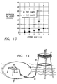
- Fig. 9 shows such a representation 81 (superposed, for comparison, on the solid line 82 representing the input pattern), for analysis of the twenty data frames mentioned earlier. The process is doing well at this reconstruction, with a signal-to-noise ratio of approximately twenty-five decibels.
- Fig. 9 shows that object perception in the output data at distances up to and probably beyond five kilometers is possible for clear water, while for dirty water the effective distance is somewhat smaller. This unidimensional simulation thus indicates that my underwater reimaging invention is feasible.
- a full two-dimensional simulation will more fully verify the technique and will also help design a real sensor for use in a field sensor requirements field of view azimuth: 360° elevation: zenith to 65° resolution at the surface 20 cm at zenith for sensor depth of 30 m (512x512-pixel array) sampling rate 10 Hz number of sensors approximately 10, about 1 m apart on 3 m x 3 m rigid platform single-pixel signal-to-noise ratio comparable to commercial video cameras with 6 good bits operating conditions any time of day possibly with sun in cloudless sky ideal sensor depth 30 m test.
- An initial design concept for this experimental sensor will follow the sensor requirements summarized in Table 1. For a field test, these requirements appear to lead toward use of a cluster of CCDs arrays, rather than a single CCD array.
- the field of view should be about 60° to 65° from the vertical, providing the total 120° to 130° cone mentioned earlier.
- Table 2 shows an initial design concept for components to be used in a sensor cluster.
- the planned field test will be conducted near a tower 83 (Fig. 14) in relatively shallow water, about thirty-five meters deep.
- the CCD cluster 84 will be held on a bottom-mounted platform 85, connected by a fiber-optic cable 86 to electronics and data processing equipment 88 on the tower.
- the viewed surface area above the platform 85 is symbolized at 87 in Fig. 14. It is planned to collect data (as video from the CCD cluster 84 at a ten-hertz data rate) and check data quality on-site. After the physical tests, planned analysis will focus on identifying cluster design 7-camera system: six around perimeter, one in center provides full coverage, minimum overlaps surface-mapped pixels (at 30 m depth) center array: 0.10 x 0.13 m keystoned outer array, inside line 0.10 x 0.123 m outside edge at 1.1 RAD angle, 0.22 x 0.26 m TI CCD array 251 h x 288 vs.
- Code for the purposes described in this document may be advantageously written in the MicroSoft® version of the familiar "Fortran” programming language, to run on an IBM-compatible general-purpose desktop computer such as the types known commercially by the designations "386" and "486". With five receivers and 1,024 parent rays per input location, one-dimensional analysis according to my invention should typically require computing time of about thirty to forty-five minutes per data set.
- an underwater lens or lens system, capable of imaging the ocean surface onto each detector array (camera) of the overall sensor.
- conventional and commercially available lenses can be used quite adequately with subdivided arrays ⁇ so as to avoid the need for custom lens design or fabrication at the outset.
- customization of larger lenses in the interest of production economies will be found well within the conventional skill in the art of underwater lenses.
- Another special optical case found to require careful handling to avoid spurious output data corresponds to a ray entering very close to a boundary between adjacent ocean-surface patches having distinctly different slopes. Actual surface slope in such a region is not well defined, but in some cases adequate processing is accomplished by proportionally splitting the ray as between the two patches. Another, simpler approach is to reject data corresponding to ray passage very close to such a boundary.
Landscapes
- Life Sciences & Earth Sciences (AREA)
- Hydrology & Water Resources (AREA)
- Physics & Mathematics (AREA)
- Engineering & Computer Science (AREA)
- General Physics & Mathematics (AREA)
- Radar, Positioning & Navigation (AREA)
- Remote Sensing (AREA)
- Image Processing (AREA)
- Measurement Of Velocity Or Position Using Acoustic Or Ultrasonic Waves (AREA)
- Investigating Or Analysing Materials By Optical Means (AREA)
- Length Measuring Devices By Optical Means (AREA)
Claims (35)
- Procédé comprenant les opérations suivantes :d'une distance se trouvant au-dessous d'une surface d'eau inégale, observer automatiquement à travers l'eau de manière directe l'intensité lumineuse respective de chaque aire d'un grand nombre d'aires de la surface d'eau inégale au moins sensiblement concurremment au moyen d'au moins un unique capteur situé en une unique position ;sur la base de l'intensité lumineuse observée pour chacune des aires, estimer automatiquement les amplitudes et les orientations des pentes de surface pour au moins certaines des zones ; etassembler automatiquement les informations d'intensité lumineuse, au moins pour des aires sélectionnées, afin de former une représentation, à plusieurs pixels, quantitative de la surface d'eau inégale.
- Procédé selon la revendication 1, comprenant en outre l'opération qui consiste à appliquer la représentation de la surface d'eau à la commande d'un processus physique choisi dans le groupe comprenant les opérations suivantes :utiliser la représentation pour la météorologie par radio et télévision en direct à destination du public, en caractérisant l'interaction entre la surface et le rayonnement électromagnétique, puis en utilisant l'interaction de rayonnement ainsi caractérisée pour affiner la caractérisation d'observations du rayonnement électromagnétique faites par des satellites au-dessus de la surface, et en utilisant ensuite la caractérisation des observations par satellites ainsi affinée pour améliorer la caractérisation et la prédiction de la météorologie par des observations de rayonnement électromagnétique effectuées par satellites ;utiliser la représentation pour la sécurité de la circulation des petits bateaux sur l'océan, en caractérisant les conditions de précipitation au-dessus de la surface, puis en utilisant les conditions de précipitation ainsi caractérisées ;utiliser la représentation pour la sécurité de la circulation des petits bateaux sur l'océan, en estimant la direction et la vitesse du vent au-dessus de la surface, puis en utilisant la direction et la vitesse du vent ainsi estimées ;utiliser la représentation pour les performances des appareils de réception du son sensibles au vent, en estimant la direction et la vitesse du vent au-dessus de la surface et en utilisant la direction et la vitesse du vent ainsi estimées pour l'orientation de groupements détecteurs acoustiques ;utiliser la représentation pour la sécurité de la circulation des navires dans des zones soumises à la présence d'icebergs, en obtenant des informations sur la présence d'icebergs et en utilisant les informations ainsi obtenues pour établir un plan en vue de l'utilisation de la surface par des navires ; etutiliser la représentation pour la sécurité de la circulation des petits bateaux sur l'océan, en associant ladite intensité lumineuse respective avec la direction au-dessus de l'eau, respective, pour chacune des aires, via l'utilisation des amplitudes et des orientations estimées des pentes de surface ; réunir les informations d'intensité lumineuse en fonction de la direction, au moins pour des aires sélectionnées, afin de déterminer s'il y a des nuages au-dessus de la surface, et en utilisant la détermination de la présence de nuages.
- Procédé selon la revendication 2, où ladite utilisation de ladite représentation pour la sécurité de la circulation des petits bateaux sur l'océan est sélectionnée dans le groupe comprenant :(1) le déplacement de petits bateaux d'un endroit à un autre,(2) l'orientation des navires sensiblement en un unique endroit, et(3) la combinaison dudit déplacement (1) et de ladite orientation (2).
- Procédé selon la revendication 1, comprenant en outre les opérations suivantes :sur la base des intensités lumineuses observées et des estimations de l'amplitude et de l'orientation des pentes, et sur la base de la représentation quantitative de la surface d'eau inégale, prédire un instant et une région limitée de surface d'eau où les conditions seront particulièrement favorables au recueil de données d'au-dessus de l'eau ;après l'opération de prédiction, depuis le dessous de la surface de l'eau, appliquer les prédictions afin de commander une observation sélective, directement à travers l'eau, de l'intensité lumineuse respective de chaque aire d'un grand nombre d'aires de la surface d'eau inégale dans la direction prédite à l'instant prédit.
- Procédé selon la revendication 4, comprenant en outre l'opération suivante :sur la base de l'intensité lumineuse sélectivement observée pour chacune des aires dans la région prédite et à l'instant prédit, estimer les amplitudes et les orientations des pentes de surface correspondantes pour au moins certaines des aires dans la région prédite et à l'instant prédit.
- Procédé selon la revendication 5, comprenant en outre les opérations suivantes :associer ladite intensité respective sélectivement observée avec l'élévation et l'azimut d'au-dessus de l'eau respectifs, pour ladite ou lesdites certaines aires dans la région prédite et à l'instant prédit, via l'utilisation des amplitudes et des orientations des pentes de surface correspondantes pour ladite ou lesdites certaines aires dans la région prédite et à l'instant prédit ; etréunir les informations d'intensité lumineuse en fonction de l'élévation et de l'azimut, au moins pour des aires sélectionnées, afin de former un groupement de données pour au moins une partie de l'espace d'au-dessus de l'eau.
- Procédé selon la revendication 6, où :ledit instant prédit et ladite région prédite sont identifiées avec la formation d'une vague relativement haute ;ladite partie d'un espace d'au-dessus de l'eau, pour laquelle ledit groupement de données est formé, se trouve à un angle relativement bas d'élévation au-dessus de l'horizon.
- Procédé selon la revendication 7, où :ladite partie se trouvant à un angle d'élévation relativement bas comprend des objets relativement éloignés dans l'espace d'au-dessus de l'eau.
- Procédé selon la revendication 6, où :ledit instant prédit et ladite région prédite sont identifiés avec la formation d'une aire de surface relativement très lisse ;ladite partie d'un espace au-dessus de l'eau, pour laquelle ledit groupement de données est formé, est une partie disposée au-delà de la zone lisse sensiblement suivant une ligne droite, mais déviée par la réfraction.
- Procédé selon la revendication 1, comprenant en outre les opérations suivantes :associer ladite intensité lumineuse respective avec une élévation et un azimut d'au-dessus de l'eau respectifs, pour ladite ou lesdites certaines aires, via l'utilisation des amplitudes et des orientations de pentes de surface estimées ; etréduire les informations d'intensité lumineuse en fonction de ladite élévation et dudit azimut, au moins pour des aires sélectionnées, afin de former une représentation d'au-dessus de l'eau.
- Procédé selon la revendication 10, comprenant en outre l'opération d'application de la représentation à la commande d'un processus physique sélectionné dans le groupe constitué des opérations suivantes :sélectivement recueillir et interpréter des informations optiques à partir d'une partie de ce qui est au-dessus de la surface, qui comporte une source d'informations optiques, afin de recevoir des informations de la source,sur la base de ladite représentation, décider s'il y a à déplacer de dessous la surface jusqu'à la surface, puis déplacer ou ne pas déplacer de dessous la surface jusqu'à la surface en fonction de ladite décision,sur la base de ladite représentation, déterminer s'il faut ou non déplacer au-dessous de la surface, de façon à éviter ou à rencontrer un objet qui est au moins partiellement sous l'eau et se trouve à une certaine distance, puis déplacer ou ne pas déplacer en fonction de ladite détermination, etafficher une image visible qui présente une intensité lumineuse en fonction de l'élévation et de l'azimut sensiblement selon ladite représentation.
- Procédé selon la revendication 11, où :l'opération d'estimation des pentes comprend la corrélation d'au moins un motif d'illumination connu d'au-dessus de la surface avec l'intensité lumineuse de certaines des aires observées depuis le dessous de la surface.
- Procédé selon la revendication 12, où :le motif d'illumination connu comporte l'éclairement direct depuis un objet astronomique dans une position connue.
- Procédé selon la revendication 12, où :le motif d'illumination connu comporte une distribution géométrique d'éclairement diffusé venant d'un objet astronomique en une position connue.
- Procédé selon la revendication 12, où :l'opération d'estimation des pentes comprend la sous-opération consistant à déterminer des limites pour les pentes de certaines aires, autres que les aires où ledit motif d'illumination connu est vu, sur la base d'une connaissance a priori du phénomène physique.
- Procédé selon la revendication 15, où :l'opération d'estimation des pentes comprend la coordination desdites sous-opérations de corrélation et de détermination de limites afin d'estimer des pentes pour encore d'autres aires.
- Procédé selon la revendication 15, où l'opération d'estimation des pentes comprend :la coordination desdites sous-opérations de corrélation et de détermination de limites afin de produire des pentes futures ; etla coordination desdites pentes futures prédites avec des sous-opérations ultérieures de corrélation et de détermination de limites afin d'affiner ladite opération d'estimation de pentes en vue d'observations faites encore ultérieurement.
- Procédé selon la revendication 10, où l'opération d'association de l'intensité comprend les sous-opérations suivantes :déterminer un angle d'observation pour chacune des aires ; etappliquer la loi de Snell aux angles d'observation déterminés et aux pentes estimées.
- Procédé selon la revendication 18, où l'opération d'association de l'intensité comprend en outre les sous-opérations suivantes :déterminer la profondeur d'observation ; etpermettre une atténuation d'intensité du fait de la distance de propagation à travers l'eau pour chacune de ladite ou desdites certaines aires.
- Procédé selon la revendication 10, où :ledit grand nombre est supérieur à 10 000.
- Procédé selon la revendication 10, où :ledit grand nombre est de l'ordre de 250 000.
- Procédé selon la revendication 11 :où le processus physique comprend l'affichage d'une image ; etcomprenant l'opération supplémentaire qui consiste, avant ou pendant l'opération d'affichage, à modifier la représentation afin de compenser la distorsion de l'élévation prenant naissance dans ladite opération d'association.
- Procédé selon la revendication 11 :où le processus physique comprend l'affichage d'une image ; etcomprenant en outre, avant l'opération d'affichage, les opérations consistant à enregistrer la représentation ou l'image, puis à extraire la représentation ou l'image enregistrée en vue de son utilisation dans l'opération d'affichage.
- Procédé selon la revendication 23, où :l'opération d'enregistrement comprend la réalisation d'un enregistrement par un moyen choisi dans le groupe comprenant une bande pour données numériques, un disque d'ordinateur, une bande vidéo, une photographie, une mémoire cache.
- Appareil permettant d'obtenir et d'utiliser une représentation d'au-dessus de la surface de l'eau, lorsque des aires de la surface d'eau sont inégales, sur la base d'observations optiques faites sensiblement concurremment depuis une distance d'au-dessous de la surface ; lesdites aires de surface inégale ayant pour effet de brouiller ce qui est au-dessus de l'eau lorsqu'on observe depuis la distance d'au-dessous de la surface ; ledit appareil comprenant :au moins un unique capteur placé en une unique position, faisant fonction de moyen capteur optique, devant être disposé à une certaine distance au-dessous de la surface afin de recevoir la lumière depuis les aires de surface à travers l'eau directement, et, en réponse, produire des signaux correspondant à l'intensité de la lumière reçue en fonction des amplitudes et des orientations des pentes de surface pour au moins certaines des aires ; etun moyen processeur programmé servant à traiter lesdits signaux afin d'analyser et de corriger au moins une partie de l'effet de brouillage des aires de surface et, ainsi, de former une représentation à plusieurs pixels d'au moins une partie de ce qui est au-dessus de l'eau.
- Appareil selon la revendication 25, comprenant en outre :un moyen d'utilisation servant à appliquer la représentation à la commande d'un processus physique.
- Appareil selon la revendication 25, où :le moyen capteur comprend un moyen permettant de produire des signaux électroniques ; etle moyen processeur comprend au moins un processeur électronique.
- Appareil selon la revendication 25, où le moyen processeur comprend :un moyen servant à former une première matrice de signaux correspondant à l'intensité de la lumière reçue en fonction de l'angle de réception ;un moyen servant à analyser la première matrice de signaux afin d'estimer les amplitudes et les orientations des pentes de surface pour un grand nombre d'aires de la surface d'eau inégale ; etun moyen servant à interpréter la première matrice de signaux, via l'utilisation des amplitudes et des orientations estimées des pentes de surface, afin de former une deuxième matrice de signaux correspondant à l'intensité de la lumière reçue en fonction de l'élévation et de l'azimut de la scène d'au-dessus de l'eau, au moins pour des aires sélectionnées.
- Appareil selon la revendication 28, comprenant en outre :un moyen servant à utiliser la deuxième matrice de signaux comme une représentation d'au moins une partie de ce qui est au-dessus de l'eau afin de commander une interaction physique avec des éléments de ce qui est au-dessus de l'eau.
- Appareil selon la revendication 25, comprenant en outre :un moyen servant à utiliser la représentation pour afficher une image intuitivement utilisable par un être humain comme analogue visuel d'au moins une partie de ce qui est au-dessus de l'eau.
- Appareil selon la revendication 30, où :l'image possède une intensité lumineuse qui est fonction de l'élévation et de l'azimut sensiblement selon au moins une partie de ladite représentation.
- Appareil selon la revendication 31, comprenant en outre :un moyen servant à modifier la représentation, avant ou pendant l'affichage, afin de corriger la distorsion d'altitude présente dans la représentation.
- Appareil selon la revendication 25, en combinaison avec :un équipement mobile portant ledit appareil, en une position propre à la réception de lumière depuis la surface de l'eau au moins lorsqu'on se trouve à une certaine distance au-dessous de la surface de l'eau.
- Appareil selon la revendication 33, comprenant en outre :un moyen d'utilisation servant à appliquer ladite représentation à la commande d'opérations de l'équipement.
- Appareil selon la revendication 34, où :le moyen d'utilisation comprend un moyen servant à appliquer ladite représentation à la commande d'opérations de l'équipement, lesdites opérations étant choisies dans le groupe comprenant le pointage et la réception de messages.
Applications Claiming Priority (3)
| Application Number | Priority Date | Filing Date | Title |
|---|---|---|---|
| US08/294,241 US5528493A (en) | 1994-08-22 | 1994-08-22 | Observations from below a rough water surface to determine conditions of or above the surface waves |
| US294241 | 1994-08-22 | ||
| PCT/IB1995/000664 WO1996006327A1 (fr) | 1994-08-22 | 1995-08-18 | Observations sous une surface d'eau agitee |
Publications (2)
| Publication Number | Publication Date |
|---|---|
| EP0776459A1 EP0776459A1 (fr) | 1997-06-04 |
| EP0776459B1 true EP0776459B1 (fr) | 2003-10-29 |
Family
ID=23132512
Family Applications (1)
| Application Number | Title | Priority Date | Filing Date |
|---|---|---|---|
| EP95927061A Expired - Lifetime EP0776459B1 (fr) | 1994-08-22 | 1995-08-18 | Observations sous une surface d'eau agitee |
Country Status (5)
| Country | Link |
|---|---|
| US (1) | US5528493A (fr) |
| EP (1) | EP0776459B1 (fr) |
| AU (1) | AU3121195A (fr) |
| DE (1) | DE69532037T2 (fr) |
| WO (1) | WO1996006327A1 (fr) |
Cited By (1)
| Publication number | Priority date | Publication date | Assignee | Title |
|---|---|---|---|---|
| RU2469361C1 (ru) * | 2011-07-08 | 2012-12-10 | Учреждение Российской академии наук Институт мониторинга климатических и экологических систем Сибирского отделения Российской академии наук (ИМКЭС СО РАН) | Способ дистанционного измерения скорости ветра |
Families Citing this family (19)
| Publication number | Priority date | Publication date | Assignee | Title |
|---|---|---|---|---|
| US5850619A (en) * | 1996-11-15 | 1998-12-15 | University Corporation For Atmospheric Research | Frozen precipitation accumlation alert system |
| US6133853A (en) | 1998-07-30 | 2000-10-17 | American Calcar, Inc. | Personal communication and positioning system |
| US6148261A (en) | 1997-06-20 | 2000-11-14 | American Calcar, Inc. | Personal communication system to send and receive voice data positioning information |
| US6035710A (en) * | 1999-05-28 | 2000-03-14 | Lockheed Martin Missiles & Space Co. | Cloud base height and weather characterization, visualization and prediction based on satellite meteorological observation |
| US6836285B1 (en) * | 1999-09-03 | 2004-12-28 | Arete Associates | Lidar with streak-tube imaging,including hazard detection in marine applications; related optics |
| US6546353B1 (en) | 1999-09-13 | 2003-04-08 | University Corporation For Atmospheric Research | Hot plate precipitation measuring system |
| KR100759346B1 (ko) * | 1999-10-19 | 2007-09-17 | 아메리칸 캘카어 인코포레이티드 | 사용자 선호도에 기초한 효과적인 내비게이션 기술 |
| EP1224577A4 (fr) | 1999-10-27 | 2003-05-28 | American Calcar Inc | Systeme et procede permettant a un utilisateur de naviguer |
| US8126960B2 (en) * | 2000-07-28 | 2012-02-28 | Silver State Intellectual Technologies, Inc. | Technique for effective organization and communication of information |
| US6872960B2 (en) * | 2001-04-18 | 2005-03-29 | Raytheon Company | Robust infrared countermeasure system and method |
| US7100438B2 (en) * | 2004-07-06 | 2006-09-05 | General Electric Company | Method and apparatus for determining a site for an offshore wind turbine |
| US20090160700A1 (en) * | 2005-07-13 | 2009-06-25 | Hagit Messer-Yaron | Monitoring and Mapping of Atmospheric Phenomena |
| US7630077B2 (en) * | 2006-10-13 | 2009-12-08 | University Of Massachusetts | System and method for imaging through an irregular water surface |
| US8207484B1 (en) | 2007-12-06 | 2012-06-26 | Voxtel, Inc. | Streak image sensor and method of operating |
| US8494697B2 (en) * | 2011-03-28 | 2013-07-23 | The Boeing Company | Methods and systems for predicting water vessel motion |
| WO2015013543A1 (fr) * | 2013-07-24 | 2015-01-29 | Digitalglobe, Inc. | Techniques bathymétriques utilisant l'imagerie satellitaire |
| RU2616354C1 (ru) * | 2015-12-10 | 2017-04-14 | Федеральное государственное бюджетное научное учреждение "Федеральный исследовательский центр Институт прикладной физики Российской академии наук" (ИПФ РАН) | Способ определения скорости ветра над водной поверхностью |
| NL2019223B1 (en) * | 2017-07-11 | 2019-01-25 | Fugro Tech Bv | Underwater Observation Unit and System |
| CN118603055B (zh) * | 2024-08-07 | 2024-10-18 | 南京波达电子科技有限公司 | 一种基于多传感器融合的波潮检测方法及智能波潮仪 |
Family Cites Families (5)
| Publication number | Priority date | Publication date | Assignee | Title |
|---|---|---|---|---|
| US3876312A (en) * | 1973-08-13 | 1975-04-08 | Fishmaster Products Inc | Water turbidity measuring apparatus |
| US4988885A (en) * | 1990-02-06 | 1991-01-29 | The United States Of America As Represented By The Secretary Of The Navy | Remote optical wave measurement sensor |
| US5311272A (en) * | 1991-08-30 | 1994-05-10 | Kaman Aerospace Corporation | Optical buoys for oceanographic measurements by imaging lidar |
| US5350922A (en) * | 1993-03-22 | 1994-09-27 | Robert Bartz | Underwater light scattering sensor |
| US5418608A (en) * | 1993-05-04 | 1995-05-23 | Harbor Branch Oceanographic Institution Inc. | Three dimensional mapping systems and methods |
-
1994
- 1994-08-22 US US08/294,241 patent/US5528493A/en not_active Expired - Lifetime
-
1995
- 1995-08-18 EP EP95927061A patent/EP0776459B1/fr not_active Expired - Lifetime
- 1995-08-18 DE DE69532037T patent/DE69532037T2/de not_active Expired - Lifetime
- 1995-08-18 WO PCT/IB1995/000664 patent/WO1996006327A1/fr not_active Ceased
- 1995-08-18 AU AU31211/95A patent/AU3121195A/en not_active Abandoned
Cited By (1)
| Publication number | Priority date | Publication date | Assignee | Title |
|---|---|---|---|---|
| RU2469361C1 (ru) * | 2011-07-08 | 2012-12-10 | Учреждение Российской академии наук Институт мониторинга климатических и экологических систем Сибирского отделения Российской академии наук (ИМКЭС СО РАН) | Способ дистанционного измерения скорости ветра |
Also Published As
| Publication number | Publication date |
|---|---|
| EP0776459A1 (fr) | 1997-06-04 |
| DE69532037T2 (de) | 2004-07-22 |
| WO1996006327A1 (fr) | 1996-02-29 |
| DE69532037D1 (de) | 2003-12-04 |
| US5528493A (en) | 1996-06-18 |
| AU3121195A (en) | 1996-03-14 |
Similar Documents
| Publication | Publication Date | Title |
|---|---|---|
| EP0776459B1 (fr) | Observations sous une surface d'eau agitee | |
| Penny et al. | Airborne laser hydrography in Australia | |
| CA2804991C (fr) | Systeme optique de veille pour systeme de veille spatiale de surveillance de l'espace proche | |
| US8917395B2 (en) | MEMS microdisplay optical imaging and sensor systems for underwater scattering environments | |
| JP6576340B2 (ja) | 水面の物体を探知するための探知システム | |
| EP2593368B1 (fr) | Procede de realisation d'un systeme de veille spatiale pour la surveillance de l'espace proche | |
| CA2805010C (fr) | Systeme de veille spatiale pour la surveillance de l'espace proche | |
| EP4308460B1 (fr) | Systeme de detection de la trajectoire d'objets mobiles | |
| EP3117260A1 (fr) | Procede de detection optique de mobiles spatiaux, systemes de telescopes pour la detection de mobiles spatiaux | |
| EP0432025B1 (fr) | Système optique de transmission de messages | |
| Bobak et al. | Aerial radiometric and video measurements of whitecap coverage | |
| EP4225650B1 (fr) | Système de détection de la trajectoire d'objets mobiles | |
| de Jong | Intensity variations of small airborne incoming targets popping up above the horizon | |
| WO2023233091A1 (fr) | Dispositif de surveillance spatiale multi-orbites | |
| Krohn et al. | Multispectral diode-based imaging laser radar | |
| Wight | First-order performance prediction techniques for charge-coupled device scanning imagers | |
| Heen et al. | Measurements of IR and visual propagation in the marine boundary layer | |
| de Jong | Geometrical image distortion and aberration for long-range targets in a non-homogeneous atmosphere | |
| Scully-Power et al. | New Advances Towards Ocean, Acoustics and Space Integration |
Legal Events
| Date | Code | Title | Description |
|---|---|---|---|
| PUAI | Public reference made under article 153(3) epc to a published international application that has entered the european phase |
Free format text: ORIGINAL CODE: 0009012 |
|
| 17P | Request for examination filed |
Effective date: 19970320 |
|
| AK | Designated contracting states |
Kind code of ref document: A1 Designated state(s): DE FR GB SE |
|
| 17Q | First examination report despatched |
Effective date: 19990507 |
|
| GRAH | Despatch of communication of intention to grant a patent |
Free format text: ORIGINAL CODE: EPIDOS IGRA |
|
| GRAH | Despatch of communication of intention to grant a patent |
Free format text: ORIGINAL CODE: EPIDOS IGRA |
|
| GRAA | (expected) grant |
Free format text: ORIGINAL CODE: 0009210 |
|
| AK | Designated contracting states |
Kind code of ref document: B1 Designated state(s): DE FR GB SE |
|
| REG | Reference to a national code |
Ref country code: GB Ref legal event code: FG4D |
|
| REF | Corresponds to: |
Ref document number: 69532037 Country of ref document: DE Date of ref document: 20031204 Kind code of ref document: P |
|
| REG | Reference to a national code |
Ref country code: SE Ref legal event code: TRGR |
|
| ET | Fr: translation filed | ||
| PLBE | No opposition filed within time limit |
Free format text: ORIGINAL CODE: 0009261 |
|
| STAA | Information on the status of an ep patent application or granted ep patent |
Free format text: STATUS: NO OPPOSITION FILED WITHIN TIME LIMIT |
|
| 26N | No opposition filed |
Effective date: 20040730 |
|
| PGFP | Annual fee paid to national office [announced via postgrant information from national office to epo] |
Ref country code: DE Payment date: 20070831 Year of fee payment: 13 |
|
| PGFP | Annual fee paid to national office [announced via postgrant information from national office to epo] |
Ref country code: GB Payment date: 20070815 Year of fee payment: 13 |
|
| PGFP | Annual fee paid to national office [announced via postgrant information from national office to epo] |
Ref country code: SE Payment date: 20070813 Year of fee payment: 13 |
|
| PGFP | Annual fee paid to national office [announced via postgrant information from national office to epo] |
Ref country code: FR Payment date: 20070712 Year of fee payment: 13 |
|
| PG25 | Lapsed in a contracting state [announced via postgrant information from national office to epo] |
Ref country code: DE Free format text: LAPSE BECAUSE OF THE APPLICANT RENOUNCES Effective date: 20080708 |
|
| EUG | Se: european patent has lapsed | ||
| GBPC | Gb: european patent ceased through non-payment of renewal fee |
Effective date: 20080818 |
|
| REG | Reference to a national code |
Ref country code: FR Ref legal event code: ST Effective date: 20090430 |
|
| PG25 | Lapsed in a contracting state [announced via postgrant information from national office to epo] |
Ref country code: FR Free format text: LAPSE BECAUSE OF NON-PAYMENT OF DUE FEES Effective date: 20080901 |
|
| PG25 | Lapsed in a contracting state [announced via postgrant information from national office to epo] |
Ref country code: GB Free format text: LAPSE BECAUSE OF NON-PAYMENT OF DUE FEES Effective date: 20080818 |
|
| PG25 | Lapsed in a contracting state [announced via postgrant information from national office to epo] |
Ref country code: SE Free format text: LAPSE BECAUSE OF NON-PAYMENT OF DUE FEES Effective date: 20080819 |