EP0776718A1 - Stangenzuführvorrichtung mit schaltbarem Vorschub für Mehrspindeldrehmaschinen - Google Patents
Stangenzuführvorrichtung mit schaltbarem Vorschub für Mehrspindeldrehmaschinen Download PDFInfo
- Publication number
- EP0776718A1 EP0776718A1 EP96118859A EP96118859A EP0776718A1 EP 0776718 A1 EP0776718 A1 EP 0776718A1 EP 96118859 A EP96118859 A EP 96118859A EP 96118859 A EP96118859 A EP 96118859A EP 0776718 A1 EP0776718 A1 EP 0776718A1
- Authority
- EP
- European Patent Office
- Prior art keywords
- drum
- bar
- pinion gear
- feeding device
- gear
- Prior art date
- Legal status (The legal status is an assumption and is not a legal conclusion. Google has not performed a legal analysis and makes no representation as to the accuracy of the status listed.)
- Granted
Links
- 230000002093 peripheral effect Effects 0.000 claims abstract description 18
- 230000008859 change Effects 0.000 claims description 2
- 230000008878 coupling Effects 0.000 description 9
- 238000010168 coupling process Methods 0.000 description 9
- 238000005859 coupling reaction Methods 0.000 description 9
- 230000008901 benefit Effects 0.000 description 7
- 229910052782 aluminium Inorganic materials 0.000 description 4
- 239000004411 aluminium Substances 0.000 description 4
- 230000003466 anti-cipated effect Effects 0.000 description 4
- 239000000463 material Substances 0.000 description 4
- XAGFODPZIPBFFR-UHFFFAOYSA-N aluminium Chemical compound [Al] XAGFODPZIPBFFR-UHFFFAOYSA-N 0.000 description 3
- 238000004873 anchoring Methods 0.000 description 3
- 238000005452 bending Methods 0.000 description 3
- 238000012423 maintenance Methods 0.000 description 3
- 229920003023 plastic Polymers 0.000 description 3
- 239000004033 plastic Substances 0.000 description 3
- 238000010276 construction Methods 0.000 description 2
- 230000009467 reduction Effects 0.000 description 2
- 230000002787 reinforcement Effects 0.000 description 2
- 150000001398 aluminium Chemical class 0.000 description 1
- 238000013459 approach Methods 0.000 description 1
- 230000015556 catabolic process Effects 0.000 description 1
- 230000001934 delay Effects 0.000 description 1
- 239000013536 elastomeric material Substances 0.000 description 1
- 230000008030 elimination Effects 0.000 description 1
- 238000003379 elimination reaction Methods 0.000 description 1
- 238000001125 extrusion Methods 0.000 description 1
- 238000004519 manufacturing process Methods 0.000 description 1
- 230000007246 mechanism Effects 0.000 description 1
- 229920002635 polyurethane Polymers 0.000 description 1
- 239000004814 polyurethane Substances 0.000 description 1
- 230000003014 reinforcing effect Effects 0.000 description 1
Images



Classifications
-
- B—PERFORMING OPERATIONS; TRANSPORTING
- B23—MACHINE TOOLS; METAL-WORKING NOT OTHERWISE PROVIDED FOR
- B23B—TURNING; BORING
- B23B13/00—Arrangements for automatically conveying or chucking or guiding stock
- B23B13/04—Arrangements for automatically conveying or chucking or guiding stock for turning-machines with a plurality of working-spindles
-
- Y—GENERAL TAGGING OF NEW TECHNOLOGICAL DEVELOPMENTS; GENERAL TAGGING OF CROSS-SECTIONAL TECHNOLOGIES SPANNING OVER SEVERAL SECTIONS OF THE IPC; TECHNICAL SUBJECTS COVERED BY FORMER USPC CROSS-REFERENCE ART COLLECTIONS [XRACs] AND DIGESTS
- Y10—TECHNICAL SUBJECTS COVERED BY FORMER USPC
- Y10T—TECHNICAL SUBJECTS COVERED BY FORMER US CLASSIFICATION
- Y10T82/00—Turning
- Y10T82/25—Lathe
- Y10T82/2514—Lathe with work feeder or remover
-
- Y—GENERAL TAGGING OF NEW TECHNOLOGICAL DEVELOPMENTS; GENERAL TAGGING OF CROSS-SECTIONAL TECHNOLOGIES SPANNING OVER SEVERAL SECTIONS OF THE IPC; TECHNICAL SUBJECTS COVERED BY FORMER USPC CROSS-REFERENCE ART COLLECTIONS [XRACs] AND DIGESTS
- Y10—TECHNICAL SUBJECTS COVERED BY FORMER USPC
- Y10T—TECHNICAL SUBJECTS COVERED BY FORMER US CLASSIFICATION
- Y10T82/00—Turning
- Y10T82/25—Lathe
- Y10T82/2514—Lathe with work feeder or remover
- Y10T82/2516—Magazine type
-
- Y—GENERAL TAGGING OF NEW TECHNOLOGICAL DEVELOPMENTS; GENERAL TAGGING OF CROSS-SECTIONAL TECHNOLOGIES SPANNING OVER SEVERAL SECTIONS OF THE IPC; TECHNICAL SUBJECTS COVERED BY FORMER USPC CROSS-REFERENCE ART COLLECTIONS [XRACs] AND DIGESTS
- Y10—TECHNICAL SUBJECTS COVERED BY FORMER USPC
- Y10T—TECHNICAL SUBJECTS COVERED BY FORMER US CLASSIFICATION
- Y10T82/00—Turning
- Y10T82/25—Lathe
- Y10T82/2514—Lathe with work feeder or remover
- Y10T82/2516—Magazine type
- Y10T82/2518—Bar feeder
-
- Y—GENERAL TAGGING OF NEW TECHNOLOGICAL DEVELOPMENTS; GENERAL TAGGING OF CROSS-SECTIONAL TECHNOLOGIES SPANNING OVER SEVERAL SECTIONS OF THE IPC; TECHNICAL SUBJECTS COVERED BY FORMER USPC CROSS-REFERENCE ART COLLECTIONS [XRACs] AND DIGESTS
- Y10—TECHNICAL SUBJECTS COVERED BY FORMER USPC
- Y10T—TECHNICAL SUBJECTS COVERED BY FORMER US CLASSIFICATION
- Y10T82/00—Turning
- Y10T82/25—Lathe
- Y10T82/2514—Lathe with work feeder or remover
- Y10T82/2521—Bar feeder
Definitions
- the present invention refers to an automatic apparatus for feeding elongated work-pieces, such as bars and the like, to multi-spindle machine tools and, more generally refers to improvements to the drive devices of the bar pushing members in bar feeders of rotating drum type, for allowing a selective operation when the feeder drum is at a standstill with a guide for the bars in a predetermined angular position, as well as when the drum is rotationally actuated by the same machine tool; in this way it is possible to anticipate the forward movement of the bars while each spindle of the machine tool is rotating and approaching to a predetermined working position.
- the apparatus comprises a frame member for supporting a bar guide drum to rotate according to a horizontal axis coinciding with the rotational axis of the spindle-holder turret of the machine tool; bar guides longitudinally extending with respect to the drum are provided in angular spaced apart positions and axially aligned to corresponding spindles of the machine tools, each guide for the bars being provided with a bar-pushing member selectively operated to move a bar forward through a respective spindle of the machine, when the drum is at a standstill, and the guide is in a predetermined angular position.
- a prior European patent application EP-A-0 123 658 discloses a drive device for the bar pushing members of a drum feeder of the know type, which uses a mechanical drive device comprising a plurality of gear members operationally connected by endless chains to a respective bar-pushing member; the various gears are radially arranged with their axis at one end of the drum to rotate with the latter, and gear coupling means being provided to connect each gear member to a power operated conical gear co-axially arranged with respect to the drum.
- a circular cam acts on the coupling means to selectively connect each pushing member to a drive motor of the central conical gear while the drum of the feeder is rotating and a selected one of the bar guides is approaching to a predetermined angular position.
- European patent application EP-A-0 174 034 discloses another mechanical solution, which is simplified in some particulars, but however always employing teeth couplings connectable to the pushing members and operating only when the drum is at a standstill condition when each guide for the bars is in correspondence of an angular position where the bars should be moved forward in the respective spindle of the machine tool.
- EP-A-0 338 606 an hydraulic solution has been suggested, according to which hydraulic drive motors are used for each pushing member, wherein the various hydraulic motors are supported at one end of the drum to be selectively fed by a suitable rotating oil distributor.
- An object of the present invention is to provide for a bar feeder for multi-spindle machine tools of the above mentioned type, which uses a mechanical solution for driving the bar-pushing members, by means of which it is possible to achieve the two aims of lightening the whole rotating structure of the drum and of allowing a selective anticipated feeding of the single bars while the drum is still rotating, which, when necessary, can be changed thus enabling the feeder to be particularly suitable for being used in multi-spindle machine tools of the fast type.
- the rotating drum is remarkably lightened, consequently reducing the risk of distortions and/or deformations of the same drum and of the bar guides, as well as damages to the same bars.
- a further object of the present invention is to provide for a bar feeder as previously referred to, wherein the drive of the pushing members is quite simplified, because it takes advantage of the rotation of the same drum to selectively connect each pushing member to a unique drive motor, by means of an original and extremely simplified gear system.
- Such a feeder requires therefore a minimum maintenance and consequently a low cost, by maintaining a high reliability degree as the number of the moving parts subjected to wear is greatly reduced with respect to a conventional bar feeding device.
- the particularly innovative and original feature of the present invention resides in the possibility to use the same rotation of the feeder drum and a particular crown wheel system to selectively connect each bar pushing member to a single drive motor.
- the proposed solution allows for driving each bar pushing member at one or more working positions and to arrange for an adequate advance angle for driving the bar pushers self-adjusting to the requirements of different working machines.
- a bar feeder for multi-spindle machine tools comprising: a support frame for a drum member rotatably supported by the frame to turn according to a horizontal axis, the drum member being provided with a plurality of bar guides longitudinally extending in angularly spaced apart positions, said bar guides being axially aligned to corresponding spindles of the machine tool; bar pushing members being slidably supported to move along said guides, in combination with a mechanical drive system comprising a plurality of peripheral crown gear members, circumferentially arranged to the rotational axis of the drum, each crown gear being operatively connected to a respective bar-pushing member, said crown gears being provided at one end of the drum and supported to rotate with respect to a central drive gear member connected to a drive motor for sliding each bar-pushing member along the guides for the bars, characterized in that said crown gears and said drive gear member are coplanary arranged with respect to each other, to provide rotational axe parallely arranged
- the feeder according to the invention substantially comprises a drum 10 constituted for example by a special section in aluminium, provided by a plurality of bar guides 11 longitudinally extending to the drum 10 in angularly spaced apart positions shown in figure 7; each guide 11 for the bars is provided with a respective bar pushing member 12 which is suitably driven to slide along the same guide 11.
- the drum 10 is supported at each end to rotate according a own longitudinal axis, by means of a disk 13 made of plastic material, provided with hollow hub 14 wherein one end of the drum 10 is fitted and suitably blocked to prevent removal of the drum.
- the disk 13 is supported to rotate by a set of idle rollers 15 provided on a support plate 16 which is part of the frame structure of the feeder.
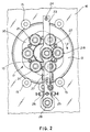
- Reference 17 in figures 1 and 2 further indicates the whole mechanical drive device of the bar pushing members 12 according to the invention.
- each pushing member 12 is supported to longitudinally slide along one guide 11 for the bars and it is connected, by means of a plate 18, to an endless chain 18A which runs inside the drum 10; at the back end of the drum which is opposed to the front end connected to the machine tool, the chain 18A engages with a cogged wheel 19 operatively connected to a cylindrical gear 21 by means of conical idle gears 20, the rotational axis of the cylindrical gear 21 being parallely arranged to the longitudinal rotational axis of the drum 10.
- the drive mechanism 17 comprises a set of gears 21 circumferentially arranged to define a crown gear system rotatably supported with the drum 10, to selectively engage and disengage a central pinion gear 28 along an arched path; each of the crown gears 21 is mechanically connected to a respective bar-pushing member 12, without any intermediate coupling member, and the crown gears 21 are coplanary arranged among each other, as well as with respect to the central pinion gear 22 connected to a rotating shaft 22A supported by a tiltable support element, for example a transversal rod 23 pivoted at its top end 24, the rod 23 near its lower end rests against two side adjustable stops members 25 which bias the rod 23 to engage the pinion gear 22 with the cylindrical gears 21, as explained further on.
- a tiltable support element for example a transversal rod 23 pivoted at its top end 24, the rod 23 near its lower end rests against two side adjustable stops members 25 which bias the rod 23 to engage the pinion gear 22 with the cylindrical gears 21, as explained further on.
- a cogged wheel 26 is provided at the rear end of the shaft 22A (figure 1), said wheel 26 being connected by a chain 27 to a second cogged wheel 28, or in another way, of a drive motor 29 which in turn is supported at the lower end of the rod 23.
- the drive motor 29 may be of any suitable type, for example hydraulic, electric or pressure air actuated type.
- crown gears 21 are provided on a support plate 30 fixed by bolts to the disk 13 maintaining a circumferential disposition of their rotational axis, parallel to the longitudinal axis of the drum.
- the engagement position of the central gear 22 with the crown gears 21 may be suitably adjusted by acting on the side stops 25. It should be noted that for simplifying the description, the position of the gear 21A, which in figure 2 is engaged with the central pinion gear 22, has been modified in figure 1 for an explaining purpose only.
- reference 21A indicates the position of each crown gear 21 when the drum is at a standstill condition in which a bar to be worked, should be fed forward for a predetermined length, through a corresponding spindle of the machine tool. Under this condition, the crown gear 21A is completely engaged with the pinion gear 22, thus maintaining a tangential arrangement of the respective "pitch line"; therefore, the drive motor 29, by the chain 27, the pinion gear 22, the gear set 21, 20, 19 and the endless chain 18A, drives the forward sliding of the pushing member 12 to move the bar into the guide 11 for a predetermined length.
- each crown gear 21 with the central pinion gear 22 may occur with a certain advance because of the rotation of the drum 10; this engagement is maintained for a predetermined rotational angle, bridging the stop position A of the drum where each guide 11 of the feeder and the respective spindle of the machine tool result positioned in correspondence of a loading and forward feeding station for the bars.
- each crown gear 21 with the pinion gear 22 occurs along an arched path having a predetermined length, comprising an inlet section B1 along which the gear 21A which is approaching to position A is engaging pinion 22, and an outlet section B2 along which the gear 21B, moving away from position A, disengages from pinion gear 22.
- the beginning of the engagement phase of the gear 21A and the end of the disengagement phase of the gear 21B may timely coincide or may occur in different moments taking advantage of the rotational movement of the drum 10 and to the particular eccentric position of the pinion gear 22 with respect to the drum 10 and the set of crown gears 21 the axis of which are arranged along a circumference concentric with the axis of the drum.
- the advanced engagement of the crown gear 21A with the gear 22 at the inlet side B1 is allowed as usually the opening of the spindle collects of a machine tool occurs in turn with a certain advance with respect to the working position where the bar is usually moved forward in the machine tool, and by the fact that the same gear 21A, owing to the rotation of the drum 10, gradually approaches the pinion gear 22 which may freely rotate by keeping the drive motor 29 in idle condition as far as the output gear 21B, in turn, is disengaged.
- the pinion gear 22 By suitably positioning the pinion gear 22 with an appropriate eccentricity both in a vertical and horizontal directions with respect to the rotational axis of the crown 10, such as in an advanced angular position with respect to position A, it is possible to change the angular ratio between the inlet section B1 and the outlet section B2, the first one being equal to or larger than the second one.
- the disengagement of the gear 20B which is leaving position A occurs before the engagement phase of the inlet gear 20B be completed; the difference existing between the two angles defines the angle advance of the gear 22 which allows for operating each crown gear 21 and therefore to move each bar pusher 12 with a certain advance while the drum 10 of the feeder is still rotating. In this way an anticipated bar feeding is obtained particularly suitable when using the feeder with machine tools of the fast type.
- the gears may be constituted of a suitable plastic material, for example of polyurethane elastomeric material having a hardness equal to or higher than 80 Shores in order to take advantage from the same elasticity of the teeth to compensate possible little interferences in the case the gear teeth are slightly elongated and ended with a rounded tip in order to avoid direct contact among the tips of the same gears 21 and 22 while they are engaging at the beginning of the inlet section B1.
- the pinion gear 22 is positioned on a bar 23 pivoted to its upper end 24.
- two adjustable stops 25 are provided on both sides, which comprise for example a bolt screwing into a corresponding support member fastened to the frame 16; acting on the bolt it is possible to make the rod 23 slightly rotate around its pivot point 24, in this way moving away or approaching the gear 22 to the gear 21 in the position A, with respect to a calculated theoretical position.
- the rod 23 and the gear 22 are prevented from rocking by two side stops 25.
- the stop device 25 on the side of the rod 20 which is opposite with respect to the engagement side between gears 21 and 22, may be subjected to an elastically yieldable spring means which tends to push and makes the rod 23 rotate the gear 22 in the engagement direction with the gears 21.
- the stop device 25 comprises a pin member 31 sliding in a hollow screw 32 which may be screwed and blocked in an adjusted position into a support bush 33 by means of a suitable locking nut, as shown.
- a spring 34 is housed into the hollow screw 32, to thrust the pin member 31 towards the bar 23 supporting the central gear 22.
- Figure 5 of the attached drawings shown a further embodiment particularly suitable to be used with machine tools having two positions for loading and moving forwards the bars, which in the example of figure 5 are shown in diametrically opposite positions.
- the bar feeder substantially comprises a hollow tubular drum 10, better shown in the detail of fig. 2.
- the drum 10 of the feeder is moreover provided, in predetermined angular positions, with a plurality of guides 11 for the bars, in which each guide 11 comprises two sets of opposed jaws, wherein a first set of jaws 35 is suitably fixed to the drum 10 by square rods 36 while the other set of jaws 37 is supported by rods 38 to rotate between open and closed conditions thus allowing the loading of a new bar in a predetermined angular position during the working cycle of the machine tool.
- the guides 11 are supported in axially spaced apart positions of the drum 10, by means of a plurality of circular sectors 39 peripherally arranged around the tubular body of the drum 10, as shown in figure 2.
- the drum 10 is in the form of a double wall cylindrical hollow body, for example aluminium extruded, comprising an external peripheral wall 40 and a plurality of reinforcement internal elements such as tubular elements 41 having the double function of reinforcing the drum 10 and housing the chains 18A and connection members 18B which drive the sliding pushing members 12 for the bars.
- each tubular element 41 inside the drum 10 opens on the peripheral surface 40 by a longitudinal slit 42 which allows the protrusion of the plate 18 to which the corresponding pushing member 12 is fixed.
- the same drum is provided with an inner wall 43 integral with the tubular elements 41 inside the drum.
- the drum 10 is moreover provided with anchoring means for the circular sectors 39 supporting the bar guides which are longitudinally extending on the outer wall 40 of the drum; in the shown case, the anchoring means comprises T-shaped ribs 44 radially extending from the peripheral surface 40 in an intermediate position between the slits 42 of two adjacent tubular elements 41.
- the anchoring means could be in turn constituted by a set of internal and/or external channel members, between the tubular elements 25.
- a hollow cylindrical body for the drum 10 provided with internal and/or external reinforcement means, allows for numerous and certain advantages, among them a higher capacity of the drum to resist to bending and torsion actions during rotation, thus allowing to maintain a perfect linearity of the guides and a perfect alignment of the bars to the spindles of the machine tool; the possibility of obtaining the cylindrical body 10 from aluminium extrusion sections remarkably reduces the weight of the drum and inertia problems when the bar feeder is connected to fast-operated machine tools. It is in fact clear from fig. 2 that the internal tubular elements 41 and the T-shaped ribs 44 co-operate to increase the resistance to the bending stress, consequently increasing the twisting torque. Moreover, the internal tubular elements 41 and the external ribs 44 are advantageously used for additional functions greatly simplifying the structure of the whole rotating drum.
- each bar guide 11 is constituted by a set of fixed jaws 35 and by a set of turntable jaws 37 connected to rods 36 and 38 supported by a plurality of shaped plates 39 circumferentially arranged on the outer wall of the drum 10.
- each support point of the guides 11 a set of shaped plates 36 is provided, the number of each being equal to the number of the guides 11, circumferentially arranged around the cylindrical body 10 of the drum.
- Each support plate 39 is in the form of a circular sector resisting on the cylindrical outer surface of the drum 10.
- Each circular sector 39 and the drum 10 are moreover provided with connecting means comprising a T-shaped slot 45 at the inside edge of plate 39, which slidingly fits on a corresponding T-shaped rib 44 of the drum 10; in this way the supporting plates 39 for the guides 11 may be easily assembled and positioned in a perfectly aligned way, by simple sliding along each rib 44 till the predetermined position of guide support.
- Each plate 39 is provided at one end with a square hole 46 through which a square rod 36 for the fixed jaws 35 is passing through and, at the other end, a circular hole 32 is provided in which a cylindrical sleeve 38 is housed for the rotation of the square rod 48 to which the mobile jaws 37 are fixed.
- each support plate 39 at each end is delimited by a flat surface which, together with the opposite flat surface of an adjacent plate, defines a radial slit 49 axially aligned with a longitudinal slit 42 on the peripheral surface of the drum 10, to allow the passage of the plate 18.
- a bar feeder for multi-spindle machine tools comprising a rotating drum having a particular structural shape, which at the same time is extremely stiff and light as it can be extruded in the form of an aluminium section with all involved functional advantages.
- the use of arch shaped plates for supporting the guides for the bars in combination with connecting means allowing sliding of the support plates during the assembling on the cylindrical drum greatly simplify the structure of the feeder with the subsequent constructive and maintenance advantages.
- a bar feeder comprising a gearing device of new design for driving the single pushing members to advance the bars along the guides on a rotating drum, and towards the respective spindles of a machine tool, in which a quite simple and advantageous use is made of the rotational movement of the same drum, to selectively engage a set of crown gears connected to the bar-pushing members, peripherally arranged around the rotational axis of the drum, with a central pinion gear in an eccentric and misaligned position, in such a way that the engagement of each crown gear is kept over a predetermined arched path, thus eliminating the use of mechanical couplings and of the cam systems employed in the bar feeder previously known.
Landscapes
- Engineering & Computer Science (AREA)
- Mechanical Engineering (AREA)
- Turning (AREA)
Applications Claiming Priority (4)
| Application Number | Priority Date | Filing Date | Title |
|---|---|---|---|
| ITMI952481 | 1995-11-28 | ||
| IT95MI002481 IT1277251B1 (it) | 1995-11-28 | 1995-11-28 | Perfezionamenti agli alimentatori di barre per macchine utensili plurimandrino |
| ITMI960436 | 1996-03-06 | ||
| IT96MI000436 IT1283197B1 (it) | 1996-03-06 | 1996-03-06 | Alimentatore di barre per torni plurimandrino,con comando selettivo |
Publications (2)
| Publication Number | Publication Date |
|---|---|
| EP0776718A1 true EP0776718A1 (de) | 1997-06-04 |
| EP0776718B1 EP0776718B1 (de) | 2001-10-31 |
Family
ID=26331328
Family Applications (1)
| Application Number | Title | Priority Date | Filing Date |
|---|---|---|---|
| EP96118859A Expired - Lifetime EP0776718B1 (de) | 1995-11-28 | 1996-11-26 | Stangenzuführvorrichtung mit schaltbarem Vorschub für Mehrspindeldrehmaschinen |
Country Status (4)
| Country | Link |
|---|---|
| US (1) | US5881617A (de) |
| EP (1) | EP0776718B1 (de) |
| CA (1) | CA2191415A1 (de) |
| DE (1) | DE69616482T2 (de) |
Cited By (1)
| Publication number | Priority date | Publication date | Assignee | Title |
|---|---|---|---|---|
| EP1980347A1 (de) * | 2007-04-12 | 2008-10-15 | Cucchi Giovanni & C.S.R.L. | Stangenzufuhrvorrichtung zum automatischen Zuführen von Stangen zu Werkzeugmaschinen, insbesondere zum Zuführen von Stangen mit unterschiedlichen Durchmessern |
Families Citing this family (9)
| Publication number | Priority date | Publication date | Assignee | Title |
|---|---|---|---|---|
| IT1299882B1 (it) * | 1998-03-05 | 2000-04-04 | Iemca Giuliani Macchine Italia | Caricatore di barre con dispositivo di preavanzamento per tornio automatico. |
| EP1089850B1 (de) * | 1998-06-09 | 2002-05-15 | Codafi S.a.r.l. | Ladevorrichtung einer werkzeugmaschine mit zuarbeitungs-stangen |
| US6302005B1 (en) | 2000-04-25 | 2001-10-16 | Mouafak C. Albasateneh | Pneumatic bar feeding apparatus for automatically feeding a plurality of bar stocks to a lathe or the like device |
| ITMI20012537A1 (it) * | 2001-11-30 | 2003-05-30 | Cucchi Pietro Spa | Alimentatore automatico di barre per torni plurimandrino |
| EP3417994B1 (de) | 2017-06-21 | 2020-08-05 | Gildemeister Italiana S.p.A. | Werkzeugmaschine, insbesondere mehrspindlige drehmaschine |
| EP3417995B8 (de) | 2017-06-21 | 2024-03-27 | DMG MORI Bergamo S.r.l. | Werkzeugmaschine, insbesondere mehrspindlige drehmaschine |
| EP3417996B1 (de) * | 2017-06-21 | 2022-03-09 | Gildemeister Italiana S.r.l. | Stangenzuführvorrichtung zur verwendung mit einer werkzeugmaschine und mit solch einer stangenzuführvorrichtung ausgestattete werkzeugmaschine |
| CN109530789B (zh) * | 2019-01-07 | 2024-08-16 | 台州市良曜成套设备有限公司 | 一种滚轮式棒材截料机 |
| JP2022547811A (ja) * | 2019-09-13 | 2022-11-16 | エルエヌエス マネジメント エス・アー・エール・エル | 加工する棒材のガイドチャネルの直径を調整するための装置 |
Citations (8)
| Publication number | Priority date | Publication date | Assignee | Title |
|---|---|---|---|---|
| US3874519A (en) | 1972-06-20 | 1975-04-01 | Toshitaka Mikami | Automatic material feeder for multispindle material working machine |
| US3955687A (en) * | 1973-12-18 | 1976-05-11 | Eunipp Ag | Apparatus for feeding workpieces into work spindles of multiple-spindle bar machines |
| US4088230A (en) | 1974-08-19 | 1978-05-09 | Hagenuk Vormals Neufeldt And Kuhnke Gmbh | Control means for a bar holder and feeder coupled to an automatic machine tool |
| US4122735A (en) * | 1976-03-06 | 1978-10-31 | Hagenuk Vormals Neufeldt & Kuhnke Gmbh | Arrangement for advancing rod stock pieces in turning machines |
| US4292864A (en) | 1978-10-05 | 1981-10-06 | Pietro Cucchi | Automatic magazine and feeder for automatic multi-mandrel lathe |
| EP0174034A1 (de) | 1984-03-09 | 1986-03-12 | F.lli CUCCHI S.r.l. | Kontrolleinrichtung des Vorschubes von Metallstäben beim Beschicken einer automatischen Mehrspindeldrehbank |
| US4604924A (en) | 1983-07-08 | 1986-08-12 | F. Lli Cucchi S.R.L. | Control device for the opening and closing of the metal bar sliding guides in an equipment for the feeding of metal bars to a multiple-spindle lathe |
| US4700593A (en) | 1985-08-30 | 1987-10-20 | Giovanni Cucchi | Guide for use in the feeding of metal bars to a machine tool |
Family Cites Families (6)
| Publication number | Priority date | Publication date | Assignee | Title |
|---|---|---|---|---|
| DE2144190C3 (de) * | 1971-09-03 | 1974-03-14 | Index-Werke Kg Hahn & Tessky, 7300 Esslingen | Stangennachschubeinrichtung für Werkzeugmaschinen, insbesondere Drehautomaten |
| EP0108182B1 (de) * | 1982-11-05 | 1986-12-17 | Sameca S.A. | Stangenführungsvorrichtung für Mehrspindel-Drehmaschinen |
| IT1161147B (it) * | 1983-04-21 | 1987-03-11 | Cucchi Flli | Dispositivo di comando per l'avanzamento di barre metalliche per l'alimentazione di un tornio automatico a mandrini multipli |
| IT1216603B (it) * | 1988-04-20 | 1990-03-08 | Cucchi Pietro & C | Dispositivo di comando dell'avanzamento di barre metalliche, con distributore e piu' motori idraulici, perl'alimentazione di un tornio automatico a mandrini multipli. |
| DE4000598C1 (de) * | 1990-01-11 | 1991-04-18 | Index-Werke Kg Hahn & Tessky, 7300 Esslingen, De | |
| DE69223265T2 (de) * | 1991-03-01 | 1998-06-18 | Kiwa Giken K K | Numerisch gesteuerte Werkzeugmaschine und Bearbeitungsverfahren |
-
1996
- 1996-11-26 EP EP96118859A patent/EP0776718B1/de not_active Expired - Lifetime
- 1996-11-26 DE DE69616482T patent/DE69616482T2/de not_active Expired - Lifetime
- 1996-11-27 CA CA002191415A patent/CA2191415A1/en not_active Abandoned
- 1996-11-29 US US08/753,731 patent/US5881617A/en not_active Expired - Lifetime
Patent Citations (8)
| Publication number | Priority date | Publication date | Assignee | Title |
|---|---|---|---|---|
| US3874519A (en) | 1972-06-20 | 1975-04-01 | Toshitaka Mikami | Automatic material feeder for multispindle material working machine |
| US3955687A (en) * | 1973-12-18 | 1976-05-11 | Eunipp Ag | Apparatus for feeding workpieces into work spindles of multiple-spindle bar machines |
| US4088230A (en) | 1974-08-19 | 1978-05-09 | Hagenuk Vormals Neufeldt And Kuhnke Gmbh | Control means for a bar holder and feeder coupled to an automatic machine tool |
| US4122735A (en) * | 1976-03-06 | 1978-10-31 | Hagenuk Vormals Neufeldt & Kuhnke Gmbh | Arrangement for advancing rod stock pieces in turning machines |
| US4292864A (en) | 1978-10-05 | 1981-10-06 | Pietro Cucchi | Automatic magazine and feeder for automatic multi-mandrel lathe |
| US4604924A (en) | 1983-07-08 | 1986-08-12 | F. Lli Cucchi S.R.L. | Control device for the opening and closing of the metal bar sliding guides in an equipment for the feeding of metal bars to a multiple-spindle lathe |
| EP0174034A1 (de) | 1984-03-09 | 1986-03-12 | F.lli CUCCHI S.r.l. | Kontrolleinrichtung des Vorschubes von Metallstäben beim Beschicken einer automatischen Mehrspindeldrehbank |
| US4700593A (en) | 1985-08-30 | 1987-10-20 | Giovanni Cucchi | Guide for use in the feeding of metal bars to a machine tool |
Cited By (1)
| Publication number | Priority date | Publication date | Assignee | Title |
|---|---|---|---|---|
| EP1980347A1 (de) * | 2007-04-12 | 2008-10-15 | Cucchi Giovanni & C.S.R.L. | Stangenzufuhrvorrichtung zum automatischen Zuführen von Stangen zu Werkzeugmaschinen, insbesondere zum Zuführen von Stangen mit unterschiedlichen Durchmessern |
Also Published As
| Publication number | Publication date |
|---|---|
| EP0776718B1 (de) | 2001-10-31 |
| DE69616482T2 (de) | 2002-05-16 |
| US5881617A (en) | 1999-03-16 |
| CA2191415A1 (en) | 1997-05-29 |
| DE69616482D1 (de) | 2001-12-06 |
Similar Documents
| Publication | Publication Date | Title |
|---|---|---|
| EP0776718B1 (de) | Stangenzuführvorrichtung mit schaltbarem Vorschub für Mehrspindeldrehmaschinen | |
| EP0349482B1 (de) | Motorisch betriebenes Handwerkzeug | |
| CN108688771B (zh) | 自行车后变速器 | |
| CA1272045A (en) | Intermittent drive mechanism | |
| CN1010189B (zh) | 钢筋捆扎机 | |
| HK1000439B (en) | Rotary drive device | |
| HK1000439A1 (en) | Rotary drive device | |
| US6343797B1 (en) | Chuck with automatically adjusted jaws and compensation of centrifugal force | |
| JP3056484B1 (ja) | 折胴の外径調節装置 | |
| CN100411809C (zh) | 机床的螺母驱动装置 | |
| JP2010213695A (ja) | 保持装置 | |
| US4538333A (en) | Apparatus for assembling two telescoping parts, of which at least one has a radially directed projection | |
| SE444704B (sv) | Till- och franslagbar kopplingsanordning | |
| EP1728574B1 (de) | Spannvorrichtung einer Werkzeugmaschine | |
| DE3014358A1 (de) | Phasensynchronisierte schaltkupplung fuer schrittgetriebe | |
| KR20130133023A (ko) | 코일 부설 헤드 | |
| US4987794A (en) | Stroke adjusting apparatus for a punching press | |
| EP1929183A1 (de) | Zahnradanordnung und stufenloses getriebe mit einer solchen zahnradanordnung | |
| CN120062323B (zh) | 一种鼓形齿链轮 | |
| KR100193458B1 (ko) | 모심기 장치 | |
| CN221340776U (zh) | 一种具有防错装结构的传动轴装配装置 | |
| SU1013123A1 (ru) | Двухкулачковый поворотный самоцентрирующий патрон | |
| ITMI960436A1 (it) | Alimentatore di barre per torni plurimandrino,con comando selettivo | |
| SU1009718A1 (ru) | Делительное устройство | |
| CN120791487B (zh) | 一种增量扩展自输送式中央刀库及其工作方法 |
Legal Events
| Date | Code | Title | Description |
|---|---|---|---|
| PUAI | Public reference made under article 153(3) epc to a published international application that has entered the european phase |
Free format text: ORIGINAL CODE: 0009012 |
|
| AK | Designated contracting states |
Kind code of ref document: A1 Designated state(s): BE CH DE FR GB LI NL SE |
|
| 17P | Request for examination filed |
Effective date: 19970728 |
|
| GRAG | Despatch of communication of intention to grant |
Free format text: ORIGINAL CODE: EPIDOS AGRA |
|
| 17Q | First examination report despatched |
Effective date: 20010212 |
|
| GRAG | Despatch of communication of intention to grant |
Free format text: ORIGINAL CODE: EPIDOS AGRA |
|
| GRAH | Despatch of communication of intention to grant a patent |
Free format text: ORIGINAL CODE: EPIDOS IGRA |
|
| GRAH | Despatch of communication of intention to grant a patent |
Free format text: ORIGINAL CODE: EPIDOS IGRA |
|
| GRAA | (expected) grant |
Free format text: ORIGINAL CODE: 0009210 |
|
| AK | Designated contracting states |
Kind code of ref document: B1 Designated state(s): BE CH DE FR GB LI NL SE |
|
| PG25 | Lapsed in a contracting state [announced via postgrant information from national office to epo] |
Ref country code: NL Free format text: LAPSE BECAUSE OF FAILURE TO SUBMIT A TRANSLATION OF THE DESCRIPTION OR TO PAY THE FEE WITHIN THE PRESCRIBED TIME-LIMIT Effective date: 20011031 Ref country code: LI Free format text: LAPSE BECAUSE OF FAILURE TO SUBMIT A TRANSLATION OF THE DESCRIPTION OR TO PAY THE FEE WITHIN THE PRESCRIBED TIME-LIMIT Effective date: 20011031 Ref country code: CH Free format text: LAPSE BECAUSE OF FAILURE TO SUBMIT A TRANSLATION OF THE DESCRIPTION OR TO PAY THE FEE WITHIN THE PRESCRIBED TIME-LIMIT Effective date: 20011031 Ref country code: BE Free format text: LAPSE BECAUSE OF FAILURE TO SUBMIT A TRANSLATION OF THE DESCRIPTION OR TO PAY THE FEE WITHIN THE PRESCRIBED TIME-LIMIT Effective date: 20011031 |
|
| REG | Reference to a national code |
Ref country code: CH Ref legal event code: EP |
|
| REF | Corresponds to: |
Ref document number: 69616482 Country of ref document: DE Date of ref document: 20011206 |
|
| REG | Reference to a national code |
Ref country code: GB Ref legal event code: IF02 |
|
| ET | Fr: translation filed | ||
| PG25 | Lapsed in a contracting state [announced via postgrant information from national office to epo] |
Ref country code: SE Free format text: LAPSE BECAUSE OF FAILURE TO SUBMIT A TRANSLATION OF THE DESCRIPTION OR TO PAY THE FEE WITHIN THE PRESCRIBED TIME-LIMIT Effective date: 20020131 Ref country code: GB Free format text: LAPSE BECAUSE OF NON-PAYMENT OF DUE FEES Effective date: 20020131 |
|
| NLV1 | Nl: lapsed or annulled due to failure to fulfill the requirements of art. 29p and 29m of the patents act | ||
| REG | Reference to a national code |
Ref country code: CH Ref legal event code: PL |
|
| PLBE | No opposition filed within time limit |
Free format text: ORIGINAL CODE: 0009261 |
|
| STAA | Information on the status of an ep patent application or granted ep patent |
Free format text: STATUS: NO OPPOSITION FILED WITHIN TIME LIMIT |
|
| GBPC | Gb: european patent ceased through non-payment of renewal fee |
Effective date: 20020131 |
|
| 26N | No opposition filed | ||
| REG | Reference to a national code |
Ref country code: FR Ref legal event code: PLFP Year of fee payment: 20 |
|
| PGFP | Annual fee paid to national office [announced via postgrant information from national office to epo] |
Ref country code: DE Payment date: 20151119 Year of fee payment: 20 |
|
| PGFP | Annual fee paid to national office [announced via postgrant information from national office to epo] |
Ref country code: FR Payment date: 20151117 Year of fee payment: 20 |
|
| REG | Reference to a national code |
Ref country code: DE Ref legal event code: R071 Ref document number: 69616482 Country of ref document: DE |