EP0776723B1 - Outil à manche rotatif - Google Patents
Outil à manche rotatif Download PDFInfo
- Publication number
- EP0776723B1 EP0776723B1 EP96118083A EP96118083A EP0776723B1 EP 0776723 B1 EP0776723 B1 EP 0776723B1 EP 96118083 A EP96118083 A EP 96118083A EP 96118083 A EP96118083 A EP 96118083A EP 0776723 B1 EP0776723 B1 EP 0776723B1
- Authority
- EP
- European Patent Office
- Prior art keywords
- rotating shaft
- tool according
- shaft tool
- force exerting
- guide
- Prior art date
- Legal status (The legal status is an assumption and is not a legal conclusion. Google has not performed a legal analysis and makes no representation as to the accuracy of the status listed.)
- Expired - Lifetime
Links
Images

Classifications
-
- B—PERFORMING OPERATIONS; TRANSPORTING
- B23—MACHINE TOOLS; METAL-WORKING NOT OTHERWISE PROVIDED FOR
- B23D—PLANING; SLOTTING; SHEARING; BROACHING; SAWING; FILING; SCRAPING; LIKE OPERATIONS FOR WORKING METAL BY REMOVING MATERIAL, NOT OTHERWISE PROVIDED FOR
- B23D77/00—Reaming tools
- B23D77/02—Reamers with inserted cutting edges
- B23D77/04—Reamers with inserted cutting edges with cutting edges adjustable to different diameters along the whole cutting length
- B23D77/042—Reamers with inserted cutting edges with cutting edges adjustable to different diameters along the whole cutting length by means of oblique planes
-
- B—PERFORMING OPERATIONS; TRANSPORTING
- B23—MACHINE TOOLS; METAL-WORKING NOT OTHERWISE PROVIDED FOR
- B23D—PLANING; SLOTTING; SHEARING; BROACHING; SAWING; FILING; SCRAPING; LIKE OPERATIONS FOR WORKING METAL BY REMOVING MATERIAL, NOT OTHERWISE PROVIDED FOR
- B23D77/00—Reaming tools
- B23D77/02—Reamers with inserted cutting edges
- B23D77/04—Reamers with inserted cutting edges with cutting edges adjustable to different diameters along the whole cutting length
- B23D77/048—Reamers with inserted cutting edges with cutting edges adjustable to different diameters along the whole cutting length by means of conical screw threads
-
- B—PERFORMING OPERATIONS; TRANSPORTING
- B23—MACHINE TOOLS; METAL-WORKING NOT OTHERWISE PROVIDED FOR
- B23D—PLANING; SLOTTING; SHEARING; BROACHING; SAWING; FILING; SCRAPING; LIKE OPERATIONS FOR WORKING METAL BY REMOVING MATERIAL, NOT OTHERWISE PROVIDED FOR
- B23D2277/00—Reaming tools
- B23D2277/08—Adjustment mechanisms
- B23D2277/081—Adjustment mechanisms for axial adjustment of the cutting edge, cutting insert or cutting bit
-
- B—PERFORMING OPERATIONS; TRANSPORTING
- B23—MACHINE TOOLS; METAL-WORKING NOT OTHERWISE PROVIDED FOR
- B23D—PLANING; SLOTTING; SHEARING; BROACHING; SAWING; FILING; SCRAPING; LIKE OPERATIONS FOR WORKING METAL BY REMOVING MATERIAL, NOT OTHERWISE PROVIDED FOR
- B23D2277/00—Reaming tools
- B23D2277/12—Reaming tools comprising balls
-
- Y—GENERAL TAGGING OF NEW TECHNOLOGICAL DEVELOPMENTS; GENERAL TAGGING OF CROSS-SECTIONAL TECHNOLOGIES SPANNING OVER SEVERAL SECTIONS OF THE IPC; TECHNICAL SUBJECTS COVERED BY FORMER USPC CROSS-REFERENCE ART COLLECTIONS [XRACs] AND DIGESTS
- Y10—TECHNICAL SUBJECTS COVERED BY FORMER USPC
- Y10T—TECHNICAL SUBJECTS COVERED BY FORMER US CLASSIFICATION
- Y10T408/00—Cutting by use of rotating axially moving tool
- Y10T408/44—Cutting by use of rotating axially moving tool with means to apply transient, fluent medium to work or product
- Y10T408/45—Cutting by use of rotating axially moving tool with means to apply transient, fluent medium to work or product including Tool with duct
-
- Y—GENERAL TAGGING OF NEW TECHNOLOGICAL DEVELOPMENTS; GENERAL TAGGING OF CROSS-SECTIONAL TECHNOLOGIES SPANNING OVER SEVERAL SECTIONS OF THE IPC; TECHNICAL SUBJECTS COVERED BY FORMER USPC CROSS-REFERENCE ART COLLECTIONS [XRACs] AND DIGESTS
- Y10—TECHNICAL SUBJECTS COVERED BY FORMER USPC
- Y10T—TECHNICAL SUBJECTS COVERED BY FORMER US CLASSIFICATION
- Y10T408/00—Cutting by use of rotating axially moving tool
- Y10T408/89—Tool or Tool with support
- Y10T408/907—Tool or Tool with support including detailed shank
-
- Y—GENERAL TAGGING OF NEW TECHNOLOGICAL DEVELOPMENTS; GENERAL TAGGING OF CROSS-SECTIONAL TECHNOLOGIES SPANNING OVER SEVERAL SECTIONS OF THE IPC; TECHNICAL SUBJECTS COVERED BY FORMER USPC CROSS-REFERENCE ART COLLECTIONS [XRACs] AND DIGESTS
- Y10—TECHNICAL SUBJECTS COVERED BY FORMER USPC
- Y10T—TECHNICAL SUBJECTS COVERED BY FORMER US CLASSIFICATION
- Y10T408/00—Cutting by use of rotating axially moving tool
- Y10T408/89—Tool or Tool with support
- Y10T408/909—Having peripherally spaced cutting edges
- Y10T408/9098—Having peripherally spaced cutting edges with means to retain Tool to support
-
- Y—GENERAL TAGGING OF NEW TECHNOLOGICAL DEVELOPMENTS; GENERAL TAGGING OF CROSS-SECTIONAL TECHNOLOGIES SPANNING OVER SEVERAL SECTIONS OF THE IPC; TECHNICAL SUBJECTS COVERED BY FORMER USPC CROSS-REFERENCE ART COLLECTIONS [XRACs] AND DIGESTS
- Y10—TECHNICAL SUBJECTS COVERED BY FORMER USPC
- Y10T—TECHNICAL SUBJECTS COVERED BY FORMER US CLASSIFICATION
- Y10T408/00—Cutting by use of rotating axially moving tool
- Y10T408/94—Tool-support
Definitions
- the invention relates to a rotating shaft tool according to the preamble of the claim 1.
- Such a rotating shank tool is known from DE-OS 42 43 586, the is designed as a machine reamer.
- This machine reamer is in one Guide slot of a body guided a knife with one end at a bolt-shaped axial adjustment is supported.
- the axial adjustment consists of a hollow cylindrical stop bolt, the slotted bolt head by means of a countersunk screw can be expanded radially, whereby the knife supported on it is moved sensitively in the radial direction to the pin axis. This allows enable precise axial adjustment.
- Such an axial adjustment is due to the tapered flank of a countersunk head the countersunk screw in the radial expansion and thus in the axial adjustment limited to a relatively short travel.
- the invention is therefore based on the object of a rotating shaft tool Generic type to create a sensitive precise adjustment of the knife in the longitudinal direction of the guide slot and an increase in the adjustment range enables.
- the at least one clamping means acting on an end face of the cutting knife with an at least spherically shaped attack surface can with an outside be easily accessible further tensioning means adjustable, with the Arrangement of the first clamping means in an adjacent to the guide slot Guide section can be given a significantly enlarged adjustment range. Due to the spherical design of the attack surface, a defined punctiform system can be created be given, whereby an axial displacement with defined power transmission ratios can take place that have only an axial force component. The knife can be easily clamped in the axial adjustment Guide slot remain so that its position immediately with a probe can be checked during adjustment.
- the arrangement according to the invention has the advantage that Deviation of the direction of movement of the further clamping means from the first Clamping device created an application-specific arrangement for shank tools that can be easily accessed from the outside.
- the first Clamping means is spherical. As a result, only very low friction losses occur, which gives a smooth and finely adjustable axial adjustment can be.
- the design and arrangement according to the invention has a spherical shape Clamping means have the advantage that the size of the adjustment range the size of the spherical formation can be given.
- the axial adjustment range is only slightly smaller than the diameter of the spherical clamping device to ensure that at maximum axial adjustment, the spherical clamping means in his leadership can be held.
- the first clamping means as a pin-shaped clamping element with a to the end face of the Cutting knife arranged spherical attack surface is provided. This can the size of the adjustment range can be further increased.
- a Force transmission between the clamping device and the further clamping device in one area can be provided between 1 ° and 90 °, preferably an area smaller / equal 45 ° is provided.
- This can create favorable transfer ratios be in which the axial infeed of the other clamping means in the same Ratio can be transferred to the axial adjustment of the cutting knife.
- the axial Clamping means essentially at right angles to the essentially axial adjustment direction of the spherical clamping means is provided. This can do the rest Clamping devices are guided radially outwards and are easily accessible from the outside.
- the additional clamping device can be in its length can be adjusted so that easy axial adjustment is maintained can be easily accessible from the outside.
- the Clamping means is provided in a guide, which is opposite an axis of rotation is inclined slightly inwards. This can be achieved in that the axial adjustment the knife in the guide slot is only adjusted axially, without this being easy Guide slot clamped cutting knife can migrate radially outwards.
- the Face of the knife an angle of less than 90 ° to the bottom of the Has guide slot.
- This can also - as through the inward incline Arrangement of the guide slot - can be achieved that in the axial adjustment, in which the knife remains slightly clamped in the guide slot, a radial outward migration can be prevented.
- both can be advantageous Embodiments, according to which an inwardly inclined guide of the spherical Clamping means acts on an end face of the knife, which is at an angle of less than 90 ° to the bottom of the guide slot is provided.
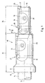
- the rotating shaft tool 10 according to FIG. 1, designed as a step reamer, has in a manner known per se, for example with respect to a geometric longitudinal axis 11 or axis of rotation 11 coaxial, cylindrical base body 12, one on the left Stop collar 13 and a clamping shaft 14.
- the stop collar 13 has an end face 15 on the shaft side, which serves to define the reamer in a defined manner align axial position with respect to a machine drill head.
- Rotation axis 11 extending guide slot 17 is formed in which an elongated leaflet-shaped knife 18 is guided and fixed by means of a clamping claw 19.
- This Training is known per se and need not be explained in more detail.
- in the The exemplary embodiment is a second in a central region of the base body 12 similar knife 21 stored in the same way. The two knives 18, 21 are intended to illustrate the importance of the axial adjustment.
- the right cutting edge 22 of the knife 21 thus has a predetermined distance 23 to the end face 15 and a further predetermined distance 24 to the right Cutting edge 25 of the knife 18. These distances must be strictly observed, and this illustrates why an axial adjustment 26, 27 is required for both knives.
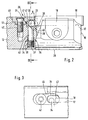
- a spherical clamping means 32 is a steel ball, as used, for example, in ball bearings is used.
- the ball 32 is axially movable in the guide section 31 and lies on an end face 33 of the cutting knife 18.
- a second guide section 34 is provided, which extends radially outward extends to the outer surface of the base body.
- a further chip means 36 axially displaceable by a designed as a threaded pin Adjustment means 37 arranged.
- the setting means 37 has a recess into which a tool can be positively positioned and the setting made possible.
- the Guide section 34 is designed as a bore in a radially outer region has a fine thread 38 for receiving the adjusting means 37. That follows a bore section with a cylindrical wall in which the pin-shaped Clamping means 36 is radially movable. So that tilting can be avoided and thus an easy adjustment of the axial adjustment 26, 27 is given are relative close tolerances between bore 33 and cylindrical clamping means 36 are provided.
- the clamping means 36 has a wedge surface 39 at its end facing the ball 32 or inclined surface which engages the ball 32.
- the clamping means 36 is moved towards the ball 32, with the formed between the wedge surface 39 and ball 32, the ball 32 axially on the End face 33 of the cutting knife 18 is moved. In doing so, force is applied the ball 32 is provided at an angle of approximately 45 °. Due to the punctiform Contact between the wedge surface 39 and the ball 32 and the guide section 31 and the ball 32 and the end face 33 and the ball 32 is an axial adjustment 26, 27 enables only minimal friction to be overcome. By the adjustment of the adjusting screw 37 can the cutting knife 18 in parallel to the axis Direction towards the end face 16 of the base body 12 moved sensitively and precisely become.
- the accuracy of the axial adjustment is in the hundredth of a millimeter range.
- a set screw 37 designed as a set screw provided has a fine thread. This can give a very fine delivery, the can be transmitted directly via the clamping means 32, 36.
- a guide section 31 For the simple production of a guide section 31 it is provided that with a Milling tool in the radial direction in the base body 12 part of the guide section is milled, which is then covered by a cover plate 41 via a detachable Screw connection 42 to a guide section 31 is formed.
- the cover plate 41 advantageously has a U-shaped recess in the direction of the end face 16 43, which at least partially the cutting knife 18 at the outlet of Grips guide slot 17. This has the further advantage that the size of the Adjustment range for the axial adjustment can be increased. Furthermore, can be ensured that the ball 32 in a maximum axial adjustment Guide section 31 can be held.
- the cover plate 41 has a radially inward facing collar 44, which ensures is that when positioning the cover plate 41 in a recess 46 of the base body 12 can be positioned and the axially and radially acting Forces of the axial adjustment 26, 27 can be safely absorbed.
- the for Guide surface 47 of the cover plate 41 facing the clamping means 32 is advantageously formed in a circular arc and on the ball diameter of the clamping means 32 customized.
- the guide strips 28 can be longer than that depending on the application Cutting knife 18 may be formed.
- the guide section 31 is longer can, in which case a plurality of clamping means 32 can be arranged one behind the other, so that the radially outwardly extending guide section 34 radially at any angle can run to the outside without being restricted by the course Guide strips 28 is given.
- An advantageous embodiment of the guide section 31, not shown, can be given that the longitudinal axis of the guide portion 31 to Rotation axis 11 is inclined inwards. This allows the clamping means 32 of act inwardly on the end face 33 of the cutting knife 18, so that the Axial adjustment the cutting knife 18 slightly clamped in the guide slot 17 only in is moved in the axial direction and a radial outward wandering can be prevented can.
- an angular arrangement of the end face 33 can also be provided, as shown in dashed lines.
- Fig. 2 the cutting knife 18 is shown in an end position in which the End face 33 rests in the base of the U-shaped recess 43.
- the clamping means 36 is moved radially towards the ball 32, whereby Via the wedge surface 29, the radial feed movement in an axial movement in the direction is implemented on the end face 16 of the base body 12 of the ball 32.
- a maximum The axial position is given when the wedge surface 39 of the clamping means 36 just touches the ball 32 tangentially.
- An intermediate position 49 is dashed shown, in which an axial adjustment 26, 27 has taken place according to the distance A.
- the wedge surface 39 of the clamping means 36 has at least a length which corresponds to the diameter of the spherical Clamping means 32 corresponds so that the maximum adjustment path can be used. Furthermore, the wedge surface 39 of the clamping means 36 must not be overdimensioned, around the base body 12 due to the then required size of the guide section 34 not to weaken.
- the clamping means 32 individually or in groups are arranged in the guide section 36, which act on the clamping means 32, the pin 40 facing the end face 33 of the cutting knife 18 End has a spherical or semicircular engagement surface 35.
- the Guide section 31 is designed as an axis-parallel bore to the axis of rotation 11.
- the balls 32 can be seen from the end face 15 in the guide section 31 are introduced, with a closure element 56, which is preferably is designed as a screw is completed.
- the closure element 56 is advantageously glued into the guide section 51 so that an unintended Loosening can be prevented.
- the adhesive connection is provided such that with a Tool the adhesive connection can be released and the closure element 56th is screwed out of the guide section 31.
- the closure element 56 has a pin-shaped section 57 pointing for axial adjustment 26, 27, the engages at least partially in the radial guide section 34.
- the pin-shaped section 57 extends so far into the guide section 34, that the axes of rotation of the clamping means 32 and 36 are offset from one another are so that a force introduction of the clamping means 32, which is also formed as a ball can be done at an angle between 89 ° and 1 °.
- the guide section 31 is longer and takes three balls 32 as an example.
- longer guide sections 31, 34 can also be provided that a combination of two clamping means 32, 36 in one Guide section 31, 34 is provided.
- a pin-shaped clamping device can be used 36 can be easily adapted to the length of the guide section 31, 34 without a suitable diameter or cross section of the guide sections 31, 34 changed should be. This allows an angular arrangement of the Guide section 34 seen in cross section, as shown in Fig. 4, are omitted.
- the axial adjustment 26, 27 is carried out analogously to the axial adjustment described in FIGS. 2 to 4 26, 27.
- the guide section 34 can be in one of the An angle of 90 ° to the guide section 34 can be provided.
- the axial adjustment 26, 27 can be provided in a step tool 10 be in which wide steps are to be worked, whereby a knife perpendicular to the Drill axis can be aligned. This allows the axial adjustment as a radial adjustment can be used to set the drill radius.
- adjusting means 37 is freely accessible from the outside is. Furthermore, such an axial adjustment 26, 27 for single-knife reamers, Step tools, fine boring tools as well as shaft tools are provided be that receive the cutting knife 18 in a cassette.
Landscapes
- Engineering & Computer Science (AREA)
- Mechanical Engineering (AREA)
- Drilling Tools (AREA)
- Replacement Of Web Rolls (AREA)
- Turning (AREA)
- Jigs For Machine Tools (AREA)
- Milling Processes (AREA)
- Knives (AREA)
- Milling, Broaching, Filing, Reaming, And Others (AREA)
- Gripping On Spindles (AREA)
Claims (22)
- Outil à manche rotatif comprenant un corps de base (12), avec une fente de guidage (17) dans le corps de base (12), dans laquelle peut être disposée au moins une lame de coupe longitudinale (18) et comprenant un dispositif d'ajustage axial (26, 27) pouvant être disposé à la sortie de la fente de guidage et permettant d'ajuster la lame de coupe (18) axialement dans la fente de guidage (17), caractérisé en ce qu'au moins un premier moyen de serrage (32), pouvant déplacer la lame de coupe (18) en direction axiale, comprenant au moins une face d'engagement (35) conçue en forme bombée sur la lame de coupe (18), peut être positionné dans un segment de guidage (31) vers la face frontale (33) de la lame de coupe (18), le moyen de serrage (32) étant ajustable avec au moins un autre moyen de serrage (36) s'écartant de la direction de déplacement du moyen de serrage (32).
- Outil à manche rotatif selon la revendication 1, caractérisé en ce que le premier moyen de serrage (32) est conçu en forme de bille.
- Outil à manche rotatif selon la revendication 1, caractérisé en ce que le premier moyen de serrage (32) est prévu sous la forme d'un élément de serrage en forme de cheville avec une surface d'engagement (35) bombée disposée vers la face frontale (33) de la lame de coupe (18).
- Outil à manche rotatif selon la revendication 1, caractérisé en ce que l'application de force entre le moyen de serrage (32) et l'autre moyen de serrage (36) est prévue suivant un angle compris entre 1° et 89°.
- Outil à manche rotatif selon la revendication 1, caractérisé en ce que l'application de force entre le moyen de serrage (32) et l'autre moyen de serrage (36) est prévue suivant un angle se trouvant dans un domaine plus ou moins égal à 50°.
- Outil à manche rotatif selon la revendication 1, caractérisé en ce que l'application de force entre le moyen de serrage (32) et l'autre moyen de serrage (36) s'effectue à environ 45°.
- Outil à manche rotatif selon l'une quelconque des revendications précédentes, caractérisé en ce que le moyen de serrage (32) est disposé dans un segment de guidage (31) d'axe parallèle à l'axe de rotation (11).
- Outil à manche rotatif selon l'une quelconque des revendications 1 à 4, caractérisé en ce que l'au moins un moyen de serrage (32) est disposé dans un segment de guidage (31) qui est incliné vers l'intérieur au moins légèrement par rapport à un axe de rotation (11).
- Outil à manche rotatif selon l'une quelconque des revendications précédentes, caractérisé en ce que le segment de guidage (31) est formé en tant qu'alésage pour recevoir l'au moins un moyen de serrage (32).
- Outil à manche rotatif selon l'une quelconque des revendications 1 à 6, caractérisé en ce que le corps de base (12) présente un évidement (46) à bords ouverts à la sortie de la fente de guidage (17), lequel peut être fermé par un élément de recouvrement (41) et forme un segment de guidage (31).
- Outil à manche rotatif selon l'une quelconque des revendications précédentes, caractérisé en ce que le moyen de serrage (32) est conçu en tant que bille d'acier.
- Outil à manche rotatif selon l'une quelconque des revendications précédentes, caractérisé en ce que l'autre moyen de serrage (36) peut être disposé dans un segment de guidage (34) qui s'étend essentiellement radialement au réglage axial.
- Outil à manche rotatif selon l'une quelconque des revendications précédentes, caractérisé en ce que l'autre moyen de serrage (36) est conçu sous la forme d'une cheville (40) susceptible d'être déplacée axialement dans le segment de guidage (34), avec une face biseautée (39) tournée vers le segment de guidage (31) .
- Outil à manche rotatif selon l'une quelconque des revendications 1 à 11, caractérisé en ce que l'autre moyen de serrage (36) est conçu en tant que bille d'acier.
- Outil à manche rotatif selon l'une quelconque des revendications précédentes, caractérisé en ce qu'il est prévu un moyen d'ajustage (37) pouvant être disposé dans le segment de guidage (34), et permettant de déplacer le moyen de serrage (36) axialement dans le segment de guidage (34).
- Outil à manche rotatif selon la revendication 14, caractérisé en ce que le moyen d'ajustage (37) est conçu en tant que vis sans tête.
- Outil à manche rotatif selon l'une quelconque des revendications précédentes, caractérisé en ce que la face frontale (33) de la lame de coupe (18) est prévue pour s'étendre vers l'extérieur à angle droit par rapport à l'axe de rotation (11).
- Outil à manche rotatif selon l'une quelconque des revendications 1 à 15, caractérisé en ce que la face frontale (33) de la lame de coupe (18) est prévue suivant un angle inférieur à 90° par rapport à la fente de guidage (17) de la lame de coupe (18).
- Outil à manche rotatif selon l'une quelconque des revendications précédentes, caractérisé en ce que plusieurs moyens de serrage (32) disposés les uns derrière les autres peuvent être disposés dans le segment de guidage (31).
- Outil à manche rotatif selon l'une quelconque des revendications précédentes, caractérisé en ce que plusieurs moyens de serrage (32) disposés les uns derrière les autres peuvent être disposés dans le segment de guidage (36).
- Outil à manche rotatif selon l'une quelconque des revendications précédentes, caractérisé en ce que la dimension maximale de la zone d'ajustage du dispositif d'ajustage axial (26, 27) peut être déterminée par le diamètre du moyen de serrage (32).
- Outil à manche rotatif selon l'une quelconque des revendications précédentes, caractérisé en ce que le segment de guidage (34) peut être guidé radialement vers l'extérieur dans une zone entre des nervures de guidage (28).
Applications Claiming Priority (2)
| Application Number | Priority Date | Filing Date | Title |
|---|---|---|---|
| DE19544378A DE19544378A1 (de) | 1995-11-29 | 1995-11-29 | Rotierendes Schaftwerkzeug |
| DE19544378 | 1995-11-29 |
Publications (2)
| Publication Number | Publication Date |
|---|---|
| EP0776723A1 EP0776723A1 (fr) | 1997-06-04 |
| EP0776723B1 true EP0776723B1 (fr) | 2000-06-28 |
Family
ID=7778630
Family Applications (1)
| Application Number | Title | Priority Date | Filing Date |
|---|---|---|---|
| EP96118083A Expired - Lifetime EP0776723B1 (fr) | 1995-11-29 | 1996-11-12 | Outil à manche rotatif |
Country Status (8)
| Country | Link |
|---|---|
| US (1) | US5820313A (fr) |
| EP (1) | EP0776723B1 (fr) |
| JP (1) | JPH09267217A (fr) |
| KR (1) | KR970025811A (fr) |
| AT (1) | ATE194094T1 (fr) |
| DE (2) | DE19544378A1 (fr) |
| DK (1) | DK0776723T3 (fr) |
| ES (1) | ES2149416T3 (fr) |
Families Citing this family (7)
| Publication number | Priority date | Publication date | Assignee | Title |
|---|---|---|---|---|
| DE10103827B4 (de) * | 2001-01-29 | 2005-12-29 | Rieter Automatik Gmbh | Messeranordnung für einen Granulator zum Granulieren von Kunststoffsträngen |
| SE526387C2 (sv) * | 2003-05-08 | 2005-09-06 | Seco Tools Ab | Borr för spånavskiljande bearbetning med alla delar utförda i ett material samt med innesluten spolkanal |
| US7357607B2 (en) * | 2003-08-07 | 2008-04-15 | Pv Engineering & Mfg., Inc. | Tool holder |
| CA2690230C (fr) | 2007-06-29 | 2014-06-10 | Allied Machine & Engineering Corp. | Systeme de foret a ejecteur |
| DE102013210355B4 (de) * | 2013-06-04 | 2022-11-17 | Kennametal Inc. | Zerspanungswerkzeug sowie Verfahren zur Herstellung eines Zerspanungswerkzeug |
| DE102014207510B4 (de) | 2014-04-17 | 2021-12-16 | Kennametal Inc. | Zerspanungswerkzeug sowie Verfahren zum Herstellen eines Zerspanungswerkzeugs |
| DE102014207507B4 (de) * | 2014-04-17 | 2021-12-16 | Kennametal Inc. | Zerspanungswerkzeug sowie Verfahren zum Herstellen eines Zerspanungswerkzeugs |
Family Cites Families (20)
| Publication number | Priority date | Publication date | Assignee | Title |
|---|---|---|---|---|
| US1713646A (en) * | 1926-09-04 | 1929-05-21 | George H Deyo | Boring head |
| US3024674A (en) * | 1959-09-17 | 1962-03-13 | Webster Mfg Inc | Multiple tool boring head with adjustable tool bits |
| DE1427182B2 (de) * | 1962-12-22 | 1971-02-11 | Mapal Fabrik fur Präzis ions werk zeuge Dr. Kress KG, 7080 Aalen | Maschmenreibahle |
| US3313186A (en) * | 1964-07-02 | 1967-04-11 | Utd Corp | Method of affixing a tube to a tool body |
| CH546614A (de) * | 1973-01-26 | 1974-03-15 | Altenrhein Flug Fahrzeug | Bohrkopf fuer langlochbohren. |
| FR2388624A1 (fr) * | 1977-04-25 | 1978-11-24 | Cri Dan | Dispositif d'alesage de tubes avec injection de liquide refrigerant |
| DE2948250A1 (de) * | 1979-11-30 | 1981-07-23 | August Beck GmbH & Co, 7472 Winterlingen | Reibahle mit einer flachrechteckfoermigen wendeschneidplatte |
| US4640652A (en) * | 1986-06-30 | 1987-02-03 | Scully-Jones Corp. | Coolant delivery system |
| IL85515A (en) * | 1988-02-19 | 1992-12-01 | Etm Eng Tool Mfg Co Ltd | Spring collets |
| JPH0247139U (fr) * | 1988-09-22 | 1990-03-30 | ||
| US5217333A (en) * | 1990-05-11 | 1993-06-08 | Valenite Inc. | Adjustable reamer |
| US5328307A (en) * | 1990-08-25 | 1994-07-12 | Mapal Fabrik Fur Prazisionswerkzeuge Dr. Kress Kg | Cutting tool for working the interior and exterior contours of workpieces |
| GB9020120D0 (en) * | 1990-09-14 | 1990-10-24 | Cridland John V | Dust collecting vacuum attachment for power drills |
| US5116172A (en) * | 1991-05-28 | 1992-05-26 | Precision Twist Drill Co. | Composite rotary cutting tool and adaptor and method of making same |
| US5199508A (en) * | 1991-08-01 | 1993-04-06 | Kabushiki Kaisha Miyanaga | Rotary hammer drill |
| DE4243586A1 (de) | 1992-12-22 | 1994-06-23 | Beck August Gmbh Co | Maschinenreibahle |
| JP3423028B2 (ja) * | 1993-04-30 | 2003-07-07 | 大昭和精機株式会社 | ホルダ装置 |
| US5544985A (en) * | 1994-09-15 | 1996-08-13 | Autodie International | Deep bore drilling apparatus with rotatable single tube system |
| US5601386A (en) * | 1995-01-18 | 1997-02-11 | Mcdonnell Douglas Corporation | Cutter body including cutting fluid gland |
| JP2943667B2 (ja) * | 1995-01-27 | 1999-08-30 | トヨタ自動車株式会社 | 工具ホルダ |
-
1995
- 1995-11-29 DE DE19544378A patent/DE19544378A1/de not_active Withdrawn
-
1996
- 1996-11-12 ES ES96118083T patent/ES2149416T3/es not_active Expired - Lifetime
- 1996-11-12 EP EP96118083A patent/EP0776723B1/fr not_active Expired - Lifetime
- 1996-11-12 AT AT96118083T patent/ATE194094T1/de not_active IP Right Cessation
- 1996-11-12 DK DK96118083T patent/DK0776723T3/da active
- 1996-11-12 DE DE59605494T patent/DE59605494D1/de not_active Expired - Fee Related
- 1996-11-22 JP JP8311858A patent/JPH09267217A/ja active Pending
- 1996-11-25 US US08/755,730 patent/US5820313A/en not_active Expired - Fee Related
- 1996-11-29 KR KR1019960059971A patent/KR970025811A/ko not_active Abandoned
Also Published As
| Publication number | Publication date |
|---|---|
| HK1019006A1 (en) | 2000-01-14 |
| DK0776723T3 (da) | 2000-11-06 |
| US5820313A (en) | 1998-10-13 |
| JPH09267217A (ja) | 1997-10-14 |
| DE59605494D1 (de) | 2000-08-03 |
| ATE194094T1 (de) | 2000-07-15 |
| KR970025811A (ko) | 1997-06-24 |
| EP0776723A1 (fr) | 1997-06-04 |
| ES2149416T3 (es) | 2000-11-01 |
| DE19544378A1 (de) | 1997-06-05 |
Similar Documents
| Publication | Publication Date | Title |
|---|---|---|
| EP0146030B1 (fr) | Outil de coupe pour l'usinage de métal par enlèvement de copeaux | |
| EP0804984B1 (fr) | Tête à aléser | |
| EP1136158B1 (fr) | Porte plaquette de coupe et plaquette du rainurage | |
| EP1321210B1 (fr) | Outil de chanfreinage | |
| EP0182290A2 (fr) | Tête de fraisage | |
| DE3240165A1 (de) | Werkzeugmaschine zum gleichzeitigen fraesen mehrerer flaechen vom freien ende eines werkstuecks her | |
| DE3824462C2 (fr) | ||
| DE3238442A1 (de) | Vorrichtung zum spangebenden erzeugen eines polygonprofils an werkstuecken | |
| EP0544658B1 (fr) | Outil de coupe servant a usiner les contours interieurs et exterieurs de pieces a usiner | |
| DE3530745A1 (de) | Messerkopf | |
| EP0776723A1 (fr) | Outil à manche rotatif | |
| DE3029133C2 (de) | Werkzeughalter | |
| DE4224772C2 (de) | Werkzeugkopf | |
| EP0175011B1 (fr) | Outil de coupe rotatif en particulier tête de foreuse | |
| DE2611146A1 (de) | Zweischneidiges ausbohrwerkzeug | |
| DE2436501B2 (de) | Bohrstange | |
| DE2064451A1 (de) | Schneidwerkzeug | |
| DE2906840C3 (de) | Aufbohrwerkzeug | |
| DE3411237A1 (de) | Zweischneidiger werkzeugeinsatz | |
| EP4076811A1 (fr) | Pièce d'outil destinée à se raccorder à une contre-pièce d'outil, contre-pièce d'outil destinée à se raccorder à une pièce d'outil, et outil | |
| DE68909645T2 (de) | Blockiereinrichtung eines Werkzeughalters in einem Werkzeugblock. | |
| DE3026513A1 (de) | Aufbohrwerkzeug, insbes. plansenker | |
| DE202006007258U1 (de) | Werkzeug zum Bearbeiten eines Rohrendes | |
| EP3838462B1 (fr) | Alésoir machine, insert de coupe et corps de base destiné à la réception des inserts de coupe | |
| DE4239701A1 (en) | Turning tool with precise end location of toolbit - which has slot down side with blind end that abuts against pin protruding through wall of toolholder |
Legal Events
| Date | Code | Title | Description |
|---|---|---|---|
| PUAI | Public reference made under article 153(3) epc to a published international application that has entered the european phase |
Free format text: ORIGINAL CODE: 0009012 |
|
| AK | Designated contracting states |
Kind code of ref document: A1 Designated state(s): AT CH DE DK ES FR GB IT LI SE |
|
| 17P | Request for examination filed |
Effective date: 19970911 |
|
| GRAG | Despatch of communication of intention to grant |
Free format text: ORIGINAL CODE: EPIDOS AGRA |
|
| GRAG | Despatch of communication of intention to grant |
Free format text: ORIGINAL CODE: EPIDOS AGRA |
|
| GRAH | Despatch of communication of intention to grant a patent |
Free format text: ORIGINAL CODE: EPIDOS IGRA |
|
| 17Q | First examination report despatched |
Effective date: 19991108 |
|
| GRAH | Despatch of communication of intention to grant a patent |
Free format text: ORIGINAL CODE: EPIDOS IGRA |
|
| GRAA | (expected) grant |
Free format text: ORIGINAL CODE: 0009210 |
|
| AK | Designated contracting states |
Kind code of ref document: B1 Designated state(s): AT CH DE DK ES FR GB IT LI SE |
|
| REF | Corresponds to: |
Ref document number: 194094 Country of ref document: AT Date of ref document: 20000715 Kind code of ref document: T |
|
| REG | Reference to a national code |
Ref country code: CH Ref legal event code: EP |
|
| REF | Corresponds to: |
Ref document number: 59605494 Country of ref document: DE Date of ref document: 20000803 |
|
| GBT | Gb: translation of ep patent filed (gb section 77(6)(a)/1977) |
Effective date: 20000726 |
|
| ITF | It: translation for a ep patent filed | ||
| REG | Reference to a national code |
Ref country code: CH Ref legal event code: NV Representative=s name: E. BLUM & CO. PATENTANWAELTE |
|
| ET | Fr: translation filed | ||
| REG | Reference to a national code |
Ref country code: ES Ref legal event code: FG2A Ref document number: 2149416 Country of ref document: ES Kind code of ref document: T3 |
|
| REG | Reference to a national code |
Ref country code: DK Ref legal event code: T3 |
|
| PLBE | No opposition filed within time limit |
Free format text: ORIGINAL CODE: 0009261 |
|
| STAA | Information on the status of an ep patent application or granted ep patent |
Free format text: STATUS: NO OPPOSITION FILED WITHIN TIME LIMIT |
|
| 26N | No opposition filed | ||
| REG | Reference to a national code |
Ref country code: GB Ref legal event code: IF02 |
|
| REG | Reference to a national code |
Ref country code: CH Ref legal event code: PFA Owner name: AUGUST BECK GMBH & CO. Free format text: AUGUST BECK GMBH & CO.#EBINGER STRASSE 115#D-72474 WINTERLINGEN (DE) -TRANSFER TO- AUGUST BECK GMBH & CO.#EBINGER STRASSE 115#D-72474 WINTERLINGEN (DE) |
|
| PGFP | Annual fee paid to national office [announced via postgrant information from national office to epo] |
Ref country code: ES Payment date: 20071120 Year of fee payment: 12 Ref country code: DK Payment date: 20071015 Year of fee payment: 12 Ref country code: DE Payment date: 20071130 Year of fee payment: 12 |
|
| PGFP | Annual fee paid to national office [announced via postgrant information from national office to epo] |
Ref country code: CH Payment date: 20071019 Year of fee payment: 12 Ref country code: IT Payment date: 20071023 Year of fee payment: 12 Ref country code: AT Payment date: 20071009 Year of fee payment: 12 |
|
| PGFP | Annual fee paid to national office [announced via postgrant information from national office to epo] |
Ref country code: SE Payment date: 20071019 Year of fee payment: 12 |
|
| PGFP | Annual fee paid to national office [announced via postgrant information from national office to epo] |
Ref country code: GB Payment date: 20071018 Year of fee payment: 12 Ref country code: FR Payment date: 20071011 Year of fee payment: 12 |
|
| REG | Reference to a national code |
Ref country code: CH Ref legal event code: PL |
|
| REG | Reference to a national code |
Ref country code: DK Ref legal event code: EBP |
|
| EUG | Se: european patent has lapsed | ||
| GBPC | Gb: european patent ceased through non-payment of renewal fee |
Effective date: 20081112 |
|
| PG25 | Lapsed in a contracting state [announced via postgrant information from national office to epo] |
Ref country code: IT Free format text: LAPSE BECAUSE OF NON-PAYMENT OF DUE FEES Effective date: 20081112 Ref country code: AT Free format text: LAPSE BECAUSE OF NON-PAYMENT OF DUE FEES Effective date: 20081112 |
|
| REG | Reference to a national code |
Ref country code: FR Ref legal event code: ST Effective date: 20090731 |
|
| PG25 | Lapsed in a contracting state [announced via postgrant information from national office to epo] |
Ref country code: LI Free format text: LAPSE BECAUSE OF NON-PAYMENT OF DUE FEES Effective date: 20081130 Ref country code: DK Free format text: LAPSE BECAUSE OF NON-PAYMENT OF DUE FEES Effective date: 20081130 Ref country code: DE Free format text: LAPSE BECAUSE OF NON-PAYMENT OF DUE FEES Effective date: 20090603 Ref country code: CH Free format text: LAPSE BECAUSE OF NON-PAYMENT OF DUE FEES Effective date: 20081130 |
|
| PG25 | Lapsed in a contracting state [announced via postgrant information from national office to epo] |
Ref country code: GB Free format text: LAPSE BECAUSE OF NON-PAYMENT OF DUE FEES Effective date: 20081112 |
|
| REG | Reference to a national code |
Ref country code: ES Ref legal event code: FD2A Effective date: 20081113 |
|
| PG25 | Lapsed in a contracting state [announced via postgrant information from national office to epo] |
Ref country code: ES Free format text: LAPSE BECAUSE OF NON-PAYMENT OF DUE FEES Effective date: 20081113 |
|
| PG25 | Lapsed in a contracting state [announced via postgrant information from national office to epo] |
Ref country code: SE Free format text: LAPSE BECAUSE OF NON-PAYMENT OF DUE FEES Effective date: 20081113 |
|
| PG25 | Lapsed in a contracting state [announced via postgrant information from national office to epo] |
Ref country code: FR Free format text: LAPSE BECAUSE OF NON-PAYMENT OF DUE FEES Effective date: 20081130 |