EP0776796A2 - Générateur pyrotechnique de gaz - Google Patents
Générateur pyrotechnique de gaz Download PDFInfo
- Publication number
- EP0776796A2 EP0776796A2 EP96119171A EP96119171A EP0776796A2 EP 0776796 A2 EP0776796 A2 EP 0776796A2 EP 96119171 A EP96119171 A EP 96119171A EP 96119171 A EP96119171 A EP 96119171A EP 0776796 A2 EP0776796 A2 EP 0776796A2
- Authority
- EP
- European Patent Office
- Prior art keywords
- charge
- housing
- gas generator
- generator according
- ignition
- Prior art date
- Legal status (The legal status is an assumption and is not a legal conclusion. Google has not performed a legal analysis and makes no representation as to the accuracy of the status listed.)
- Ceased
Links
- 239000003380 propellant Substances 0.000 claims abstract description 21
- 230000000694 effects Effects 0.000 claims description 5
- 238000004519 manufacturing process Methods 0.000 description 2
- 238000005192 partition Methods 0.000 description 2
- 239000000654 additive Substances 0.000 description 1
- 230000000996 additive effect Effects 0.000 description 1
- 238000005452 bending Methods 0.000 description 1
- 230000015572 biosynthetic process Effects 0.000 description 1
- 239000003795 chemical substances by application Substances 0.000 description 1
- 230000000254 damaging effect Effects 0.000 description 1
- 230000001419 dependent effect Effects 0.000 description 1
- 230000001066 destructive effect Effects 0.000 description 1
- 230000007613 environmental effect Effects 0.000 description 1
- 238000007373 indentation Methods 0.000 description 1
- 239000000463 material Substances 0.000 description 1
- 230000007704 transition Effects 0.000 description 1
- 230000001960 triggered effect Effects 0.000 description 1
- 230000003313 weakening effect Effects 0.000 description 1
Images
Classifications
-
- B—PERFORMING OPERATIONS; TRANSPORTING
- B60—VEHICLES IN GENERAL
- B60R—VEHICLES, VEHICLE FITTINGS, OR VEHICLE PARTS, NOT OTHERWISE PROVIDED FOR
- B60R21/00—Arrangements or fittings on vehicles for protecting or preventing injuries to occupants or pedestrians in case of accidents or other traffic risks
- B60R21/02—Occupant safety arrangements or fittings, e.g. crash pads
- B60R21/16—Inflatable occupant restraints or confinements designed to inflate upon impact or impending impact, e.g. air bags
- B60R21/26—Inflatable occupant restraints or confinements designed to inflate upon impact or impending impact, e.g. air bags characterised by the inflation fluid source or means to control inflation fluid flow
- B60R21/264—Inflatable occupant restraints or confinements designed to inflate upon impact or impending impact, e.g. air bags characterised by the inflation fluid source or means to control inflation fluid flow using instantaneous generation of gas, e.g. pyrotechnic
- B60R21/2644—Inflatable occupant restraints or confinements designed to inflate upon impact or impending impact, e.g. air bags characterised by the inflation fluid source or means to control inflation fluid flow using instantaneous generation of gas, e.g. pyrotechnic using only solid reacting substances, e.g. pellets, powder
-
- B—PERFORMING OPERATIONS; TRANSPORTING
- B60—VEHICLES IN GENERAL
- B60R—VEHICLES, VEHICLE FITTINGS, OR VEHICLE PARTS, NOT OTHERWISE PROVIDED FOR
- B60R22/00—Safety belts or body harnesses in vehicles
- B60R22/34—Belt retractors, e.g. reels
- B60R22/46—Reels with means to tension the belt in an emergency by forced winding up
- B60R22/4628—Reels with means to tension the belt in an emergency by forced winding up characterised by fluid actuators, e.g. pyrotechnic gas generators
-
- B—PERFORMING OPERATIONS; TRANSPORTING
- B60—VEHICLES IN GENERAL
- B60R—VEHICLES, VEHICLE FITTINGS, OR VEHICLE PARTS, NOT OTHERWISE PROVIDED FOR
- B60R21/00—Arrangements or fittings on vehicles for protecting or preventing injuries to occupants or pedestrians in case of accidents or other traffic risks
- B60R21/02—Occupant safety arrangements or fittings, e.g. crash pads
- B60R21/16—Inflatable occupant restraints or confinements designed to inflate upon impact or impending impact, e.g. air bags
- B60R21/26—Inflatable occupant restraints or confinements designed to inflate upon impact or impending impact, e.g. air bags characterised by the inflation fluid source or means to control inflation fluid flow
- B60R21/264—Inflatable occupant restraints or confinements designed to inflate upon impact or impending impact, e.g. air bags characterised by the inflation fluid source or means to control inflation fluid flow using instantaneous generation of gas, e.g. pyrotechnic
- B60R21/2644—Inflatable occupant restraints or confinements designed to inflate upon impact or impending impact, e.g. air bags characterised by the inflation fluid source or means to control inflation fluid flow using instantaneous generation of gas, e.g. pyrotechnic using only solid reacting substances, e.g. pellets, powder
- B60R2021/2648—Inflatable occupant restraints or confinements designed to inflate upon impact or impending impact, e.g. air bags characterised by the inflation fluid source or means to control inflation fluid flow using instantaneous generation of gas, e.g. pyrotechnic using only solid reacting substances, e.g. pellets, powder comprising a plurality of combustion chambers or sub-chambers
Definitions
- the invention relates to a pyrotechnic gas generator with the features of the preamble of claim 1.
- Such a gas generator is known from DE 42 28 696 A1, in the housing of which an ignition device at one end of the housing, a first propellant charge and finally a second propellant charge are arranged in the longitudinal direction adjacent to an outlet opening at the other end of the housing, so that the first of the ignition device Propellant charge is ignited and the second propellant charge is ignited by its expansion.
- the object of the present invention is to improve a pyrotechnic gas generator of the type mentioned at the outset, so that the course of the rise in pressure of the pressure or drive gas generated is optimized with regard to parts to be driven.
- the gas generator When the compressed gas escapes from the initial charge, the gas generator provides a first drive gas, which is used comparatively gently and thus creates a pressure curve that can initially drive or inflate moving components without extremely large load peaks with a damaging or destructive effect.
- the ignition control device causes the compressed gas to ignite the main charge when a limit value is exceeded, the compressed gas of which starts with a time delay set in this way before the pressure of the initial charge drops, so that the overall effect of the compressed or drive gas emerging from the housing of the two-stage or multi-stage gas generator can develop continuously and without excessive pressure peaks.
- the Ignition control device can contain, for example, sensors that measure the pressure rise and cause the main charge to ignite.
- the ignition control device comprises a partition or boundary wall delimiting the main charge, in which one or more openings or bores are contained, through which the compressed gas generated by the initial charge can act on the main charge and can trigger its ignition.
- the housing of the gas generator can be rectangular or cylindrical, in particular rotationally symmetrical, and the gas outlet can also be divided into two or more housing openings.
- the housing is expediently a sleeve-shaped cartridge which has the ignition device at one end and the housing opening at the opposite end for the discharge of the compressed gas.
- a cartridge can be produced easily and inexpensively, especially if it is a rotationally symmetrical part.
- the housing opening for the compressed gas outlet is closed before the propellant charges are ignited. Then the propellant loads are protected against environmental influences.
- the closure of the housing opening is opened by the pressure force of the initial charge.
- the closure of the housing opening can be an inserted and attached to the cartridge closure part such. B. be a lid.
- the front part of the cartridge wall is expediently pressed and deformed in such a way that the cartridge wall forms the openable closure of the housing opening.
- the cartridge wall can be designed such that the initial charge immediately opens the maximum opening cross section.
- the initial charge only opens a first smaller cross section, which is opened to the maximum cross section by the main charge. The course of the pressure rise can thus be influenced. Weaknesses in the wall thickness, indentations in the wall or the like at defined points can support the desired deformation of the outer wall of the cartridge.
- the main charge is contained in a cavity of the housing adjacent to the housing opening and the initial charge is contained in a further cavity of the housing adjacent to the cavity of the main charge in the direction of the ignition device, the main charge having a secondary housing which has at least one of the Boundary wall delimits flow channel in the cavity for the discharge of the compressed gas from the initial charge to the housing opening.
- This design forms a defined gas outflow path via an arbitrary, but as flow-free as possible, flow channel past the main charge.
- the main charge is separated from the flow channel by the boundary wall, in which the openings of the ignition control device are contained.
- the secondary housing is expediently designed as a cup-like ring with a central axial flow channel, since then the compressed gas of the initial charge flows axially out of the housing in the shortest possible way and can thereby ignite the main charge.
- the flow channel can also be designed as an annular channel which surrounds a cylindrical secondary housing.
- Part of the initial charge can also be contained in part of the flow channel, so that a larger propellant charge of the initial charge can be accommodated with the same cartridge housing dimensions.
- the amount of propellant charge in the initial and main charge and the type of propellant, e.g. B. the burning rate can be varied.
- the ignition control device can also influence the pressure gas development and thus the pressure behavior by varying the number, the positioning and the diameter of the openings in the boundary wall.
- the design of the tip of the cartridge and the opening behavior of the closure of the housing opening also offer the possibility of influencing the pressure behavior.
- the main charge described can also be divided into a plurality of individual charges, which can be ignited together or in succession by the ignition control device in order to achieve optimum pressure behavior.
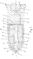
- the exemplary embodiment of a pyrotechnic gas generator shown in FIG. 1 contains a cartridge housing 1 which is rotationally symmetrical with respect to its longitudinal axis 2. At its rear end 3 (right end according to FIG. 1), the cartridge housing 1 has a recess 4 in which an ignition device 5 of a known type with an electrical or mechanical igniter with an ignition charge is arranged.
- An axial ignition channel 6 connects to the recess 4 in the direction of the front end 7 (left end according to FIG. 1) of the cartridge housing 1.
- the ignition channel 6 opens into a first cavity 8, in which a first charge of primary agent or initial charge 9 of a propellant set of the gas generator is arranged.
- the first cavity 8 is followed by a second cavity 10 with a larger cross section than the first cavity 8.
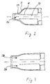
- This second cavity 10 has an approximately cylindrical basic shape and tapers towards the front end 7 of the cartridge housing 1 into a curve 10 that closes the cavity 10 or a tip 11 shown in FIG. B. is formed by pressing together the front annular wall portion 12 of
- a second propellant charge or main charge 13 of the propellant set is contained in an annular, cup-like secondary housing 14 which is arranged in the second cavity 10 of the cartridge housing 1, the cross section of the secondary housing 14 being matched to the cross section of the cavity 10.
- An annular bottom wall piece 15 of the secondary housing 14 lies on a shoulder 16 at the transition from the first to the second cavity 8 or 10 to, wherein a cover plate 17 may be interposed between the paragraph 14 and the bottom wall piece 15 to the z.
- the cover plate 17 consists of a material which can be easily torn open by the compressed gas of the initial charge 9, for. B. from cardboard, plastic or the like.
- the secondary housing 14 has a tubular inner partition or boundary wall 18, which forms a central axial longitudinal channel 19 through the main charge 13 and thus an inner boundary of the main charge 13 to the longitudinal channel 19.
- An annular outer wall 20 of the secondary housing 14 abuts an outer wall 21 of the cartridge housing 1 surrounding the second cavity 10, is adapted in its front section 22 to the inside of the tapered outer wall 21 of the cartridge housing 1 and, as shown, can also be in the axial direction Stand front end 7 beyond the inner boundary wall 18.
- the front section 22 of the outer wall 20 is deformed symmetrically to the longitudinal axis 2 in the form of a projectile tip in the manufacture of the unit consisting of the main charge 13 with its secondary housing 14, so that the annular interior for the main charge 13 by contact of the front section 22 of the outer wall 20 with the front edge 23 of the inner boundary wall 18 is closed in the axial direction and also the longitudinal channel 19 is largely or completely closed by pressing together the outer wall 20 in the tip.
- the front annular wall region 12 of the cartridge housing 1 is deformed in the direction of the longitudinal axis 2, the outer wall 21 of the cartridge being deformed against the front section 22 of the outer wall 20 of the Adapts secondary housing 14 and thus closes the original opening of the cavity 10.
- the secondary housing 14 contains an ignition control device 24, which in the tubular inner boundary wall 18 has a plurality of radial through holes or openings 25 which are uniformly distributed on the circumference of the boundary wall 18 and are arranged in the vicinity of the open front end of the longitudinal channel 19. According to In the illustration in FIG. 1, four openings 25 are provided by way of example, but the number and the arrangement and also the respective diameter of the openings 25 can be varied in order to obtain a desired response or ignition behavior of the ignition control device 24.
- the ignition device 5 When the ignition device 5 is triggered, its ignition charge ignites the initial charge 9 via the ignition channel 6.
- the compressed gas front meets the inside of the inside curved outer wall 22 of the secondary housing 14 and presses this together with the front wall section 12 of the cartridge housing 1 to the outside, an opening 26 (see schematic representation in FIG. 2) forming for the outflow of the compressed gas.
- Notches or weakenings 27 can be provided on the outer walls 21 or 22 in order to promote the bending of the outer walls 21, 22 at defined points.
- the tip 11 can also be made with a small initial opening 26 so that a first quantity of compressed gas can escape before the two outer walls 21, 22 are bent open.
- the compressed gas front flows through the longitudinal channel 19, it passes through the openings 25 of the ignition control device 24, through which it hits the main charge 13 and ignites it. Due to a short delay until the ignition, the pressure gas formation of the main charge 13 only begins after the pressure gas of the initial charge 9 has expanded the housing opening 26 and a first, comparatively smoothly acting drive effect on movable parts, for. B. a belt tensioner of a motor vehicle or an inflatable airbag.
- the compressed gas of the main charge 13 expands the outer walls 21, 22 and enlarges the front housing opening 26, an annular opening 28 being formed between the front end 23 of the tubular inner boundary wall 18 and the outer wall 22, via which the compressed gas of the main charge 13 can flow out quickly.
- the two additive pressure curves result in a gentle increase in the drive effect by the initial charge 9 and a subsequent use of the main charge 13, which results in a delay continuous pressure increase to a maximum value with a subsequent high pressure level when the main charge 13 burns.
- the initial charge 9 can also be arranged in a ring shape instead of in a cylindrical arrangement in the cavity 8.
- the main charge 13 is then arranged in an approximately cylindrical secondary housing in the cavity 10, the outside diameter of the secondary housing being smaller than the inside diameter of the cavity 10, so that an annular flow channel for the compressed gas of the initial charge 9 is formed.
- the outer boundary wall surrounding the main charge 13 then contains the openings of the ignition control device 24.
Landscapes
- Engineering & Computer Science (AREA)
- Mechanical Engineering (AREA)
- Physics & Mathematics (AREA)
- Fluid Mechanics (AREA)
- Air Bags (AREA)
Applications Claiming Priority (2)
| Application Number | Priority Date | Filing Date | Title |
|---|---|---|---|
| DE19544784 | 1995-11-30 | ||
| DE1995144784 DE19544784C2 (de) | 1995-11-30 | 1995-11-30 | Pyrotechnischer Gasgenerator |
Publications (2)
| Publication Number | Publication Date |
|---|---|
| EP0776796A2 true EP0776796A2 (fr) | 1997-06-04 |
| EP0776796A3 EP0776796A3 (fr) | 1997-12-10 |
Family
ID=7778896
Family Applications (1)
| Application Number | Title | Priority Date | Filing Date |
|---|---|---|---|
| EP96119171A Ceased EP0776796A3 (fr) | 1995-11-30 | 1996-11-29 | Générateur pyrotechnique de gaz |
Country Status (2)
| Country | Link |
|---|---|
| EP (1) | EP0776796A3 (fr) |
| DE (1) | DE19544784C2 (fr) |
Cited By (6)
| Publication number | Priority date | Publication date | Assignee | Title |
|---|---|---|---|---|
| EP0867347A3 (fr) * | 1997-03-24 | 1999-11-10 | Daicel Chemical Industries, Ltd. | Pastilles génératrices de gaz, générateur de gaz et dispositif de coussin gonflable |
| EP0926015A3 (fr) * | 1997-12-26 | 2000-05-24 | Daicel Chemical Industries, Ltd. | Générateur de gaz pour coussin gonflable de sécurité et dispositif de coussin gonflable |
| US6562161B1 (en) | 1997-03-24 | 2003-05-13 | Daicel Chemical Industries, Ltd. | Gas generating compositions for air bag |
| WO2013133349A1 (fr) * | 2012-03-06 | 2013-09-12 | Daicel Corporation | Générateur de gaz pour dispositif de maintien |
| US20250076010A1 (en) * | 2021-11-30 | 2025-03-06 | Daicel Corporation | Gas generator |
| US20250091544A1 (en) * | 2022-06-06 | 2025-03-20 | Daicel Corporation | Gas generator |
Families Citing this family (4)
| Publication number | Priority date | Publication date | Assignee | Title |
|---|---|---|---|---|
| US6116642A (en) * | 1998-04-27 | 2000-09-12 | Trw Inc. | Inflator for inflating an inflatable vehicle occupant protection device |
| DE102015009001B4 (de) * | 2015-07-10 | 2021-10-28 | Nitrochemie Aschau Gmbh | Pyrotechnischer Gasgenerator |
| DE102015220108B4 (de) * | 2015-10-15 | 2017-12-28 | Takata AG | Gasgeneratorbaugruppe mit Brennkammer |
| DE102016015042B4 (de) | 2016-12-16 | 2018-08-23 | Diehl Defence Gmbh & Co. Kg | Munitionsmodul, Gefechtskopf und Munition |
Citations (1)
| Publication number | Priority date | Publication date | Assignee | Title |
|---|---|---|---|---|
| DE4228696A1 (de) | 1992-08-28 | 1994-03-03 | Hs Tech & Design | Pyrotechnischer Gasgenerator |
Family Cites Families (6)
| Publication number | Priority date | Publication date | Assignee | Title |
|---|---|---|---|---|
| US3715131A (en) * | 1971-06-04 | 1973-02-06 | Hercules Inc | Chemical gas generating device for an automobile safety system |
| DE2364268C3 (de) * | 1973-12-22 | 1980-07-03 | Rudolf 8025 Unterhaching Reiter | Feststoffgasgenerator, inbesondere zum Aufblasen eines dem Schütze von Fahrzeuginsassen dienenden Gassacks |
| DE4019677A1 (de) * | 1990-06-20 | 1992-01-09 | Bayern Chemie Gmbh Flugchemie | Airbagsystem |
| DE4019877A1 (de) * | 1990-06-22 | 1992-01-09 | Bayern Chemie Gmbh Flugchemie | Gasgenerator fuer den insassenschutz in fahrzeugen |
| SE9202078D0 (sv) * | 1992-07-06 | 1992-07-06 | Bergslagens Produktutveckling | Taendanordning foer gasgeneratorer |
| US5345875A (en) * | 1993-07-07 | 1994-09-13 | Automotive Systems Laboratory, Inc. | Gas generator |
-
1995
- 1995-11-30 DE DE1995144784 patent/DE19544784C2/de not_active Expired - Fee Related
-
1996
- 1996-11-29 EP EP96119171A patent/EP0776796A3/fr not_active Ceased
Patent Citations (1)
| Publication number | Priority date | Publication date | Assignee | Title |
|---|---|---|---|---|
| DE4228696A1 (de) | 1992-08-28 | 1994-03-03 | Hs Tech & Design | Pyrotechnischer Gasgenerator |
Cited By (14)
| Publication number | Priority date | Publication date | Assignee | Title |
|---|---|---|---|---|
| EP0867347A3 (fr) * | 1997-03-24 | 1999-11-10 | Daicel Chemical Industries, Ltd. | Pastilles génératrices de gaz, générateur de gaz et dispositif de coussin gonflable |
| US6562161B1 (en) | 1997-03-24 | 2003-05-13 | Daicel Chemical Industries, Ltd. | Gas generating compositions for air bag |
| EP0926015A3 (fr) * | 1997-12-26 | 2000-05-24 | Daicel Chemical Industries, Ltd. | Générateur de gaz pour coussin gonflable de sécurité et dispositif de coussin gonflable |
| US6540256B2 (en) | 1997-12-26 | 2003-04-01 | Daicel Chemical Industries, Ltd. | Airbag gas generator and an airbag apparatus |
| US6942249B2 (en) | 1997-12-26 | 2005-09-13 | Daicel Chemical Industries, Ltd. | Airbag gas generator and an airbag apparatus |
| JP2013184482A (ja) * | 2012-03-06 | 2013-09-19 | Daicel Corp | 乗員拘束装置用ガス発生器 |
| WO2013133349A1 (fr) * | 2012-03-06 | 2013-09-12 | Daicel Corporation | Générateur de gaz pour dispositif de maintien |
| US8720947B2 (en) | 2012-03-06 | 2014-05-13 | Daicel Corporation | Gas generator for restraining device |
| CN104159792A (zh) * | 2012-03-06 | 2014-11-19 | 株式会社大赛璐 | 用于约束装置的气体发生器 |
| CN104159792B (zh) * | 2012-03-06 | 2016-12-14 | 株式会社大赛璐 | 用于约束装置的气体发生器 |
| US20250076010A1 (en) * | 2021-11-30 | 2025-03-06 | Daicel Corporation | Gas generator |
| EP4442518A4 (fr) * | 2021-11-30 | 2025-11-19 | Daicel Corp | Générateur de gaz |
| US12595991B2 (en) * | 2021-11-30 | 2026-04-07 | Daicel Corporation | Gas generator |
| US20250091544A1 (en) * | 2022-06-06 | 2025-03-20 | Daicel Corporation | Gas generator |
Also Published As
| Publication number | Publication date |
|---|---|
| DE19544784A1 (de) | 1997-06-05 |
| EP0776796A3 (fr) | 1997-12-10 |
| DE19544784C2 (de) | 2003-02-13 |
Similar Documents
| Publication | Publication Date | Title |
|---|---|---|
| DE69624112T2 (de) | Azidfreier zweikammer-generator | |
| EP0782945B1 (fr) | Générateur de gaz pour système de retenue dans un véhicule | |
| EP2195205B1 (fr) | Generateur de gaz pour un module d'airbag | |
| EP0776796A2 (fr) | Générateur pyrotechnique de gaz | |
| EP0656522B1 (fr) | Douille pour cartouche | |
| DE4324554B4 (de) | Gasgenerator, insbesondere für einen Airbag | |
| DE4228696C2 (de) | Pyrotechnischer Gasgenerator | |
| EP1012005B1 (fr) | Generateur de gaz | |
| DE69920615T2 (de) | Kolbenantrieb zum Strammen eines Sicherheitsgurtes | |
| DE69809860T2 (de) | Anpassungsfähiger pyrotechnischer Gasgenerator für einen Airbag mit Neutralisierungsvorrichtung | |
| EP0944504B1 (fr) | Generateur de gaz hybride pour un airbag | |
| DE20219899U1 (de) | Gasgenerator | |
| DE602004000593T2 (de) | Pyrotechnischer Stellantrieb mit variabler Schubkraft | |
| DE4124490A1 (de) | Kartusche aus kunststoff und kartuschen-bandmagazin aus kunststoff | |
| WO2019020414A1 (fr) | Système de protection contre le surallumage, second étage d'allumage, générateur de gaz ainsi que module airbag | |
| EP0882627B1 (fr) | Générateur de gaz et méthode de fonctionnement d'un générateur de gaz | |
| DE4213265C2 (de) | Treibgasgeneratoranordnung | |
| EP0882628A1 (fr) | Générateur de gaz | |
| DE29617587U1 (de) | Druckgasspeicher für ein Fahrzeuginsassen-Rückhaltesystem | |
| DE3717458A1 (de) | Pyrotechnisches kraftelement | |
| DE19804655C2 (de) | Airbagmodul mit seitlich verlagerbaren Abdeckkappen | |
| DE102016107114B3 (de) | Gasgeneratorbaugruppe | |
| AT526224B1 (de) | Pyrotechnischer Aktuator | |
| DE602005006148T2 (de) | Pyrotechnisches betätigungsglied mit steuerbarer kraft und optimierter geometrie | |
| DE4239167A1 (de) | Gasgenerator für eine Gassack-Einheit |
Legal Events
| Date | Code | Title | Description |
|---|---|---|---|
| PUAI | Public reference made under article 153(3) epc to a published international application that has entered the european phase |
Free format text: ORIGINAL CODE: 0009012 |
|
| AK | Designated contracting states |
Kind code of ref document: A2 Designated state(s): AT DE ES FR GB IT |
|
| PUAL | Search report despatched |
Free format text: ORIGINAL CODE: 0009013 |
|
| AK | Designated contracting states |
Kind code of ref document: A3 Designated state(s): AT DE ES FR GB IT |
|
| 17P | Request for examination filed |
Effective date: 19980605 |
|
| 17Q | First examination report despatched |
Effective date: 20000112 |
|
| STAA | Information on the status of an ep patent application or granted ep patent |
Free format text: STATUS: THE APPLICATION HAS BEEN REFUSED |
|
| 18R | Application refused |
Effective date: 20010106 |