EP0776809A1 - Schubkarre und Lastförderwagen - Google Patents
Schubkarre und Lastförderwagen Download PDFInfo
- Publication number
- EP0776809A1 EP0776809A1 EP96440001A EP96440001A EP0776809A1 EP 0776809 A1 EP0776809 A1 EP 0776809A1 EP 96440001 A EP96440001 A EP 96440001A EP 96440001 A EP96440001 A EP 96440001A EP 0776809 A1 EP0776809 A1 EP 0776809A1
- Authority
- EP
- European Patent Office
- Prior art keywords
- axis
- wheelbarrow
- wheel
- stirrup
- chassis
- Prior art date
- Legal status (The legal status is an assumption and is not a legal conclusion. Google has not performed a legal analysis and makes no representation as to the accuracy of the status listed.)
- Granted
Links
- 230000006835 compression Effects 0.000 claims abstract description 5
- 238000007906 compression Methods 0.000 claims abstract description 5
- 238000006243 chemical reaction Methods 0.000 claims description 4
- 238000006073 displacement reaction Methods 0.000 claims description 3
- 239000013536 elastomeric material Substances 0.000 claims description 3
- 230000000284 resting effect Effects 0.000 claims description 3
- 230000000694 effects Effects 0.000 description 3
- 238000000034 method Methods 0.000 description 3
- 239000000725 suspension Substances 0.000 description 3
- 238000013016 damping Methods 0.000 description 2
- 229920001971 elastomer Polymers 0.000 description 2
- 239000000806 elastomer Substances 0.000 description 2
- 238000005096 rolling process Methods 0.000 description 1
- 230000035939 shock Effects 0.000 description 1
Images

Classifications
-
- B—PERFORMING OPERATIONS; TRANSPORTING
- B62—LAND VEHICLES FOR TRAVELLING OTHERWISE THAN ON RAILS
- B62B—HAND-PROPELLED VEHICLES, e.g. HAND CARTS OR PERAMBULATORS; SLEDGES
- B62B1/00—Hand carts having only one axis carrying one or more transport wheels; Equipment therefor
- B62B1/18—Hand carts having only one axis carrying one or more transport wheels; Equipment therefor in which the load is disposed between the wheel axis and the handles, e.g. wheelbarrows
-
- B—PERFORMING OPERATIONS; TRANSPORTING
- B62—LAND VEHICLES FOR TRAVELLING OTHERWISE THAN ON RAILS
- B62B—HAND-PROPELLED VEHICLES, e.g. HAND CARTS OR PERAMBULATORS; SLEDGES
- B62B2301/00—Wheel arrangements; Steering; Stability; Wheel suspension
- B62B2301/20—Resilient wheel suspension using springs
Definitions
- the present invention relates to wheelbarrows and similar handling carts comprising a single wheel located at the front of a chassis supporting a tank. It relates more particularly to the trolleys of this type called “suspension", in which is provided an elastic means allowing said wheel to be easily raised to overcome the obstacles it encounters.
- the wheel is located substantially in front of the elastic means used, the fixed point of which is conversely located substantially behind the carriage.
- the invention relates to an embodiment in which said arc of a circle has its center towards the front of the wheelbarrow, in front of the wheel itself which, in contact with the obstacle, rolls vertically along this obstacle by tending to bypass it from above and forward, which represents a much softer and regular method of depreciation.
- a wheelbarrow or similar handling device comprising at its front part at least one wheel pivoting about a horizontal axis and capable of coming into contact with a relief constituting an obstacle, creating a reaction force directed towards the axis of the wheel and decomposing into a horizontal component directed towards the rear and a vertical component directed upwards, of the type in which means are associated with said axis to allow the wheel to be lifted to more easily cross said relief
- said means consist of at least one element which can take an angular displacement, around a fixed point of the chassis of the device and carrying said axis at an end relatively distant towards the rear relative to this fixed point, so that, under the action of said vertical component, said element deviates angularly from its normal position by r epos, by driving said axis upwards, following a path in an arc, the center of which is said fixed point, against elastic restoring forces bringing said element with said axis back to their normal positions after crossing said relief.
- the invention relates to a certain number of embodiments, in which all of said elastic forces result from the potential expansion energy accumulated by said element during its deformation under the action of said vertical component.
- said element is a pivoting rigid part subjected to a spring and said elastic return forces result from the compression action of this spring by said part.
- said rigid part has the shape of a stirrup mounted rocking about at least one axis carried by the front portion of the chassis of the wheelbarrow, and open towards the rear, the rear ends of the branches of this stirrup carrying the axis of the wheel, and the front portion of this stirrup comprising a stop compressing an elastic element such as a spring or a block of elastomeric material.
- the portion of the wheelbarrow chassis located in front of said axis having the shape of a substantially horizontal hoop bringing together the two side rails of said chassis to form a stopper, said elastic element is placed on this stopper, a plate located at the front of said stirrup being located on said elastic element.
- the chassis of the wheelbarrow comprising only two lateral beams, not joined by a stopper, said stirrup is also open at its front part, the front ends of its two branches each include a plate which is placed each on the 'one of the two elastic elements each placed towards the front end of one of said side rails.
- the tipping point of the stirrup on the chassis of the wheelbarrow be located so that the distance from this point to the axis of the wheel is substantially greater than its distance from said stop.
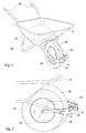
- FIGS 1A and 1B there is shown symbolically in profile a wheelbarrow consisting of a tank 1, mounted on a frame 2 having arms 3, and resting on the one hand on a fixed rear leg 4, and on the other hand on a wheel 5 carried by the front of the chassis 2.
- said wheel 5 was mounted at the front end of an elastic assembly 6, the point of flexion 7 of which was located far behind the wheel 5.
- the elastic assembly is a fork articulated at 7 below the chassis 2, and capable of being lifted in opposition to a spring 8, the elements 6, 7, 8 being all located behind the wheel 5.
- the reaction force F decomposed into a horizontal component directed towards the rear F R and a vertical component F v directed upwards, so that the axis 10 of the wheel tended to move along an arc C of center 7, therefore whose concavity was turned towards the rear.
- the pushing force on the wheelbarrow to cross the obstacle therefore tended to roll back the wheel, which came in contradiction with the desired goal.
- the elastic assembly constituted by the fork 16, carrying the wheel 15 and the elastic element 18, is articulated at 17 to the chassis 2 at a point situated in front of the wheel 15, the spring (or similar elastic element) 18 being situated even further forward, beyond the point of articulation 17.
- the tank of the wheelbarrow has been designated by 21, carried by a frame 22 comprising arms 23, fixed feet 24 and a front fork 25, on which is mounted an elastic assembly carrying the wheel 26.
- This assembly is consists of a stirrup 27 mounted tilting on an axis 28 mounted transversely to the fork 25, the axle 29 of the wheel 26 being carried by the rear ends of the arms of the stirrup 27, while the front portion of said stirrup comprises a stop 30 compressing an elastic element having, in the case shown, the form of an elastomer block 31.
- the tipping point 28 of the stirrup 27 is situated completely at the front of the longitudinal beams 22 'of the chassis 22, while the axis 29 of the wheel 26 is located at a point of the stirrup 27 relatively very distant towards the rear of the axis 28, and that the stop 30 situated at the front of the stirrup 27 is relatively much closer towards the front of the axis 28.
- the result is a very significant leverage effect, ensuring, when suspending the wheelbarrow and absorbing shocks and vibrations when encountering obstacles, maximum softness.
- stirrup 27 can, in the context of the invention, also be open, the front ends of each of its forks then each comprising a stop similar to 30, compressing an elastic element similar to 31, carried by the front end of each beam 22 '.
- elastic element 31 it is possible to use an elastomer block having the coefficient of elasticity appropriate to the desired degree of damping.
Landscapes
- Engineering & Computer Science (AREA)
- Chemical & Material Sciences (AREA)
- Combustion & Propulsion (AREA)
- Transportation (AREA)
- Mechanical Engineering (AREA)
- Handcart (AREA)
- Control Of Vehicles With Linear Motors And Vehicles That Are Magnetically Levitated (AREA)
- Carriages For Children, Sleds, And Other Hand-Operated Vehicles (AREA)
- Cultivation Of Seaweed (AREA)
- Micro-Organisms Or Cultivation Processes Thereof (AREA)
Applications Claiming Priority (2)
| Application Number | Priority Date | Filing Date | Title |
|---|---|---|---|
| FR9506276A FR2734536B1 (fr) | 1995-05-22 | 1995-05-22 | Brouette ou analogue adaptee au franchissement d'obstacles |
| FR9506276 | 1995-05-22 |
Publications (2)
| Publication Number | Publication Date |
|---|---|
| EP0776809A1 true EP0776809A1 (de) | 1997-06-04 |
| EP0776809B1 EP0776809B1 (de) | 1997-06-25 |
Family
ID=9479403
Family Applications (1)
| Application Number | Title | Priority Date | Filing Date |
|---|---|---|---|
| EP96440001A Expired - Lifetime EP0776809B1 (de) | 1995-05-22 | 1996-01-05 | Schubkarre und Lastförderwagen |
Country Status (4)
| Country | Link |
|---|---|
| EP (1) | EP0776809B1 (de) |
| AT (1) | ATE154789T1 (de) |
| DE (1) | DE69600029T2 (de) |
| FR (1) | FR2734536B1 (de) |
Families Citing this family (2)
| Publication number | Priority date | Publication date | Assignee | Title |
|---|---|---|---|---|
| FR2768983B1 (fr) | 1997-10-01 | 1999-12-10 | Thibault Essieux Rtn Sa | Dispositif de transport de charges, tel que brouette, muni de moyens amortisseurs |
| AU201711183S (en) * | 2016-09-02 | 2017-03-15 | Razor Usa Llc | Airless tire |
Citations (7)
| Publication number | Priority date | Publication date | Assignee | Title |
|---|---|---|---|---|
| GB426986A (en) * | 1934-03-28 | 1935-04-12 | Harry Jubb | Improvements in and relating to wheelbarrows |
| US2176780A (en) * | 1937-08-12 | 1939-10-17 | Walter W Wood | Spring suspension device |
| FR966856A (fr) * | 1948-05-26 | 1950-10-20 | Perfectionnements apportés aux brouettes | |
| FR1281947A (fr) * | 1960-11-10 | 1962-01-19 | Brouette à roue traînée | |
| GB2156288A (en) * | 1983-08-01 | 1985-10-09 | Robert James Clements | Wheelbarrow with spring suspension |
| FR2613308A1 (fr) | 1987-04-01 | 1988-10-07 | Curaudeau Bernard | Brouette equipee d'un dispositif amortisseur de chocs |
| FR2692218A1 (fr) | 1992-03-19 | 1993-12-17 | Thirrouetz Patrice | Brouette à suspension variable. |
Family Cites Families (1)
| Publication number | Priority date | Publication date | Assignee | Title |
|---|---|---|---|---|
| FR1443663A (fr) * | 1964-08-06 | 1966-06-24 | Engin formant brouette et remorque |
-
1995
- 1995-05-22 FR FR9506276A patent/FR2734536B1/fr not_active Expired - Fee Related
-
1996
- 1996-01-05 EP EP96440001A patent/EP0776809B1/de not_active Expired - Lifetime
- 1996-01-05 AT AT96440001T patent/ATE154789T1/de active
- 1996-01-05 DE DE69600029T patent/DE69600029T2/de not_active Expired - Fee Related
Patent Citations (7)
| Publication number | Priority date | Publication date | Assignee | Title |
|---|---|---|---|---|
| GB426986A (en) * | 1934-03-28 | 1935-04-12 | Harry Jubb | Improvements in and relating to wheelbarrows |
| US2176780A (en) * | 1937-08-12 | 1939-10-17 | Walter W Wood | Spring suspension device |
| FR966856A (fr) * | 1948-05-26 | 1950-10-20 | Perfectionnements apportés aux brouettes | |
| FR1281947A (fr) * | 1960-11-10 | 1962-01-19 | Brouette à roue traînée | |
| GB2156288A (en) * | 1983-08-01 | 1985-10-09 | Robert James Clements | Wheelbarrow with spring suspension |
| FR2613308A1 (fr) | 1987-04-01 | 1988-10-07 | Curaudeau Bernard | Brouette equipee d'un dispositif amortisseur de chocs |
| FR2692218A1 (fr) | 1992-03-19 | 1993-12-17 | Thirrouetz Patrice | Brouette à suspension variable. |
Also Published As
| Publication number | Publication date |
|---|---|
| FR2734536B1 (fr) | 1997-07-11 |
| ATE154789T1 (de) | 1997-07-15 |
| EP0776809B1 (de) | 1997-06-25 |
| DE69600029T2 (de) | 1998-02-05 |
| DE69600029D1 (de) | 1997-08-14 |
| FR2734536A1 (fr) | 1996-11-29 |
Similar Documents
| Publication | Publication Date | Title |
|---|---|---|
| EP0252851B1 (de) | Zusammenlegbarer Handwagen, bestimmt für z.B. den Transport von Taschen für Golfclubs | |
| EP0464078A1 (de) | Drehgestell mit verformbarem rahmen sowie verfahren und teilesatz zur verbesserung eines solchen drehgestells | |
| EP1349769A1 (de) | Klappfahrrad | |
| EP0113260A2 (de) | Transportwagen, insbesondere für die Kundschaft von Selbstbedienungsläden | |
| EP0776809A1 (de) | Schubkarre und Lastförderwagen | |
| EP0204637A1 (de) | Bewegliche Werkbank mit rein mechanischen Bewegungsmitteln | |
| FR2770479A1 (fr) | Chariot pliable | |
| EP1381524B1 (de) | Vorrichtung zur verbesserung der manövrierfähigkeit eines transportwagens | |
| EP0266232A1 (de) | Hubwerk für Ladebordwände von Strassentransportfahrzeugen | |
| EP0757132B1 (de) | Brückenteil, insbesondere zur Überwindung von Gräben durch Fahrzeuge und System zum transportieren und ablegen von solchen Brückenteilen | |
| FR2614862A1 (fr) | Dispositif de suspension pour poussette ou analogue | |
| FR2584696A1 (fr) | Chariot elevateur | |
| FR2587691A2 (fr) | Appareil de manutention destine a hisser des charges sur le toit d'un vehicule | |
| FR2698063A1 (fr) | Chariot porte-palettes. | |
| EP1502811B1 (de) | Montagevorrichtung für einen Behälter auf einem Fahrzeugrahmen und Kipp-Lastwagen mit solcher Vorrichtung | |
| FR2567471A1 (fr) | Chariot pliant | |
| FR2608532A1 (fr) | Ensemble porteur tracte avec ensemble de manoeuvre pour le pliage et le depliage d'une travure | |
| FR2908092A1 (fr) | Dispositif de chargement et/ou dechargement d'un vehicule de transport, module de plancher d'un vehicule de transport et vehicule de transport | |
| FR2818606A1 (fr) | Dispositif a chenille pour circulation en terrain accidente | |
| EP1468892B1 (de) | Selbstbremsender Lasttransportkarren | |
| FR2705939A1 (fr) | Chariot franchisseur d'obstacle. | |
| WO1996038331A1 (fr) | Chariot d'achat pour magasins a libre-service | |
| CA2127949C (fr) | Rampe "get-in" | |
| FR2802823A3 (fr) | Maquette de vehicule utilitaire a plusieurs essieux comportant des bras auxiliaires | |
| EP1029766A1 (de) | Stapelbare Wagen besonders geeignet zum Transpotieren von sperrigen Gegenständen |
Legal Events
| Date | Code | Title | Description |
|---|---|---|---|
| GRAG | Despatch of communication of intention to grant |
Free format text: ORIGINAL CODE: EPIDOS AGRA |
|
| GRAH | Despatch of communication of intention to grant a patent |
Free format text: ORIGINAL CODE: EPIDOS IGRA |
|
| GRAH | Despatch of communication of intention to grant a patent |
Free format text: ORIGINAL CODE: EPIDOS IGRA |
|
| PUAI | Public reference made under article 153(3) epc to a published international application that has entered the european phase |
Free format text: ORIGINAL CODE: 0009012 |
|
| GRAA | (expected) grant |
Free format text: ORIGINAL CODE: 0009210 |
|
| 17P | Request for examination filed |
Effective date: 19960129 |
|
| AK | Designated contracting states |
Kind code of ref document: A1 Designated state(s): AT BE CH DE DK ES FR GB GR IE IT LI LU MC NL PT SE |
|
| AK | Designated contracting states |
Kind code of ref document: B1 Designated state(s): AT BE CH DE DK ES FR GB GR IE IT LI LU MC NL PT SE |
|
| PG25 | Lapsed in a contracting state [announced via postgrant information from national office to epo] |
Ref country code: NL Free format text: LAPSE BECAUSE OF FAILURE TO SUBMIT A TRANSLATION OF THE DESCRIPTION OR TO PAY THE FEE WITHIN THE PRESCRIBED TIME-LIMIT Effective date: 19970625 Ref country code: IT Free format text: LAPSE BECAUSE OF FAILURE TO SUBMIT A TRANSLATION OF THE DESCRIPTION OR TO PAY THE FEE WITHIN THE PRE;WARNING: LAPSES OF ITALIAN PATENTS WITH EFFECTIVE DATE BEFORE 2007 MAY HAVE OCCURRED AT ANY TIME BEFORE 2007. THE CORRECT EFFECTIVE DATE MAY BE DIFFERENT FROM THE ONE RECORDED.SCRIBED TIME-LIMIT Effective date: 19970625 Ref country code: GR Free format text: LAPSE BECAUSE OF FAILURE TO SUBMIT A TRANSLATION OF THE DESCRIPTION OR TO PAY THE FEE WITHIN THE PRESCRIBED TIME-LIMIT Effective date: 19970625 Ref country code: GB Effective date: 19970625 Ref country code: ES Free format text: THE PATENT HAS BEEN ANNULLED BY A DECISION OF A NATIONAL AUTHORITY Effective date: 19970625 Ref country code: DK Effective date: 19970625 Ref country code: AT Effective date: 19970625 |
|
| REF | Corresponds to: |
Ref document number: 154789 Country of ref document: AT Date of ref document: 19970715 Kind code of ref document: T |
|
| REG | Reference to a national code |
Ref country code: CH Ref legal event code: EP |
|
| REF | Corresponds to: |
Ref document number: 69600029 Country of ref document: DE Date of ref document: 19970814 |
|
| PG25 | Lapsed in a contracting state [announced via postgrant information from national office to epo] |
Ref country code: SE Effective date: 19970925 Ref country code: PT Effective date: 19970925 |
|
| NLV1 | Nl: lapsed or annulled due to failure to fulfill the requirements of art. 29p and 29m of the patents act | ||
| GBV | Gb: ep patent (uk) treated as always having been void in accordance with gb section 77(7)/1977 [no translation filed] |
Effective date: 19970625 |
|
| PG25 | Lapsed in a contracting state [announced via postgrant information from national office to epo] |
Ref country code: LU Free format text: LAPSE BECAUSE OF NON-PAYMENT OF DUE FEES Effective date: 19980105 |
|
| PG25 | Lapsed in a contracting state [announced via postgrant information from national office to epo] |
Ref country code: BE Free format text: LAPSE BECAUSE OF NON-PAYMENT OF DUE FEES Effective date: 19980131 |
|
| PG25 | Lapsed in a contracting state [announced via postgrant information from national office to epo] |
Ref country code: IE Free format text: LAPSE BECAUSE OF NON-PAYMENT OF DUE FEES Effective date: 19980330 |
|
| REG | Reference to a national code |
Ref country code: IE Ref legal event code: FD4D Ref document number: 74847 Country of ref document: IE |
|
| PLBE | No opposition filed within time limit |
Free format text: ORIGINAL CODE: 0009261 |
|
| STAA | Information on the status of an ep patent application or granted ep patent |
Free format text: STATUS: NO OPPOSITION FILED WITHIN TIME LIMIT |
|
| 26N | No opposition filed | ||
| BERE | Be: lapsed |
Owner name: S.A. HAEMMERLIN Effective date: 19980131 |
|
| PG25 | Lapsed in a contracting state [announced via postgrant information from national office to epo] |
Ref country code: MC Free format text: LAPSE BECAUSE OF NON-PAYMENT OF DUE FEES Effective date: 19980731 |
|
| PG25 | Lapsed in a contracting state [announced via postgrant information from national office to epo] |
Ref country code: LI Free format text: LAPSE BECAUSE OF NON-PAYMENT OF DUE FEES Effective date: 20000131 Ref country code: CH Free format text: LAPSE BECAUSE OF NON-PAYMENT OF DUE FEES Effective date: 20000131 |
|
| REG | Reference to a national code |
Ref country code: CH Ref legal event code: PL |
|
| REG | Reference to a national code |
Ref country code: FR Ref legal event code: CJ Ref country code: FR Ref legal event code: CD |
|
| PGFP | Annual fee paid to national office [announced via postgrant information from national office to epo] |
Ref country code: DE Payment date: 20080131 Year of fee payment: 13 |
|
| PGFP | Annual fee paid to national office [announced via postgrant information from national office to epo] |
Ref country code: FR Payment date: 20080125 Year of fee payment: 13 |
|
| PG25 | Lapsed in a contracting state [announced via postgrant information from national office to epo] |
Ref country code: DE Free format text: LAPSE BECAUSE OF NON-PAYMENT OF DUE FEES Effective date: 20090801 |
|
| REG | Reference to a national code |
Ref country code: FR Ref legal event code: ST Effective date: 20091030 |
|
| PG25 | Lapsed in a contracting state [announced via postgrant information from national office to epo] |
Ref country code: FR Free format text: LAPSE BECAUSE OF NON-PAYMENT OF DUE FEES Effective date: 20090202 |