EP0776844B1 - Vorrichtung zum Durchführen von Auzeichnungsträgern in Druckern - Google Patents
Vorrichtung zum Durchführen von Auzeichnungsträgern in Druckern Download PDFInfo
- Publication number
- EP0776844B1 EP0776844B1 EP96308326A EP96308326A EP0776844B1 EP 0776844 B1 EP0776844 B1 EP 0776844B1 EP 96308326 A EP96308326 A EP 96308326A EP 96308326 A EP96308326 A EP 96308326A EP 0776844 B1 EP0776844 B1 EP 0776844B1
- Authority
- EP
- European Patent Office
- Prior art keywords
- media
- door
- tray
- doors
- printer
- Prior art date
- Legal status (The legal status is an assumption and is not a legal conclusion. Google has not performed a legal analysis and makes no representation as to the accuracy of the status listed.)
- Expired - Lifetime
Links
Images


Classifications
-
- B—PERFORMING OPERATIONS; TRANSPORTING
- B65—CONVEYING; PACKING; STORING; HANDLING THIN OR FILAMENTARY MATERIAL
- B65H—HANDLING THIN OR FILAMENTARY MATERIAL, e.g. SHEETS, WEBS, CABLES
- B65H3/00—Separating articles from piles
- B65H3/44—Simultaneously, alternately, or selectively separating articles from two or more piles
Definitions
- the present invention relates to media (paper and the like) pass-through apparatus for a printer and more particularly relates to apparatus which permits easy passage for media to bypass other options, if necessary, while also providing enhanced user access to media storage for media replacement and for clearing incidental media jams.
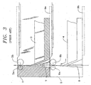
- Fig. 3 of the accompanying drawings a fragmentary side elevational view of the prior art such as illustrated in the above identified patents, is shown.
- a pair of cassettes 1,2, carrying stacks of media such as cut sheet paper 3,4 of different sizes, e.g. letter and legal respectively, are shown in superimposed, overlapping relation.
- the cassettes are trays mounted for sliding ingress and egress with respect to a printer on racks 9a, 9b which may be connected to or form part of the frame (not shown) of the printer.
- the paper in each of the cassettes is fed upwardly between the nip of pinch rolls 5a, 5b, 6a, 6b respectively as by sheet feeder mechanism (not shown) but such as illustrated in our U.S.
- Each of the cassettes 1,2 has a media guide passage 7,8 therethrough respectively, which passages are aligned when the cassettes are positioned in the printer to permit guided transition of paper from the lower cassette 2 through the upper cassette 1 to the print engine of the printer.
- the cassettes may be stacked.
- the cassettes must be removable, preferably from the front, so that they can be reloaded with new media by the operator-user.
- Media from an "underneath" tray is fed through the guide passages located in each of the above trays.
- the slot is molded as an integral part of the tray structure. When the tray is pulled out for reloading, the pass-through slot is also removed (since it is part of the tray itself).
- paper must be removed from the guide passages 7 and 8 and the pinch rollers 5a, 5b, 6a, 6b, usually by tearing.
- the pass-through passage is formed as part of the front cover, which is lowered, much like an oven door, to permit entrance to and egress from the media loaded tray or' cassette. While there are advantages to this type of structure, the lowering of the door places the guide for the media, from the lower cassette or tray, in the path of the cassette or tray as it is removed from the printer. Unless the operator is careful, the tray will either damage the guides on the door, or the cassette, or both. Moreover, if there is a paper jam above or below the door, excessive tension may be placed on the paper as the door is opened which can likewise damage the machine, parts of the paper path etc, or can make the jam difficult to remove.
- US-A-5155537 discloses media pass-through apparatus in a printer in which media is fed from a removable media tray or other media holder, through a media path to a print engine, said apparatus comprising:
- the present invention is characterised in that the said door opens and closes substantially about one longitudinal edge of said media path to said print engine, and in that one of said pinch rolls is mounted on said door and the other pinch roll is mounted on said frame.
- the invention creates two related configurations for passing media in front of a printer media input module or "tray" from which media is fed from superimposed and removable media holders or trays through a media path to a print engine.
- a rack in the frame of the printer is dimensioned for receiving at least one media carrying, removable tray disposed beneath the print engine.
- a door, hinge and latch combination is provided, the hinge connected intermediate the door and frame of the printer so that the door opens in a plane swingable substantially about one longitudinally extending edge of the media path to the print engine, and outwardly and away from the front of the tray.
- the latch is positioned remotely from the hinge for selectively attaching the door to the printer in a position confronting the tray when the door is in a closed or first position, and open or in a second position for facilitating (unimpeded) tray removal.
- Media guide means are mounted on the interior of the door for guiding different media in front of the tray, into the media guide path and to the print engine.
- the media guide means includes a chute having converging interior walls therein for urging media therethrough in a predetermined path.
- the media guide means includes a portion of the chute on the door and a second portion of the chute formed on the portion of the tray confronting the interior of the door.
- the doors may be individually opened to allow entrance to the confronting media tray or ganged to permit simultaneous access to all the trays and media being fed to the print engine.
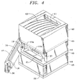
- a schematic perspective view of a printer 10 incorporating a novel media pass-through configuration of the present invention is illustrated therein.
- the printer 10 may be connected directly to, for example, a computer (not shown) or connected to a network and act as the printer for multiple computers, either operating locally or remotely.
- the printer 10 contains multiple media carrying trays 15,20 and 25, each of the trays being loaded with media such as cut sheet paper, and each capable of carrying varying media sizes (e.g. letter, legal, A4 etc.).
- the trays may be mounted integrally with the printer 10 or may be contained in separate, stackable, modular, media feed options, such as the modules 11,12 and 13 illustrated in Figs. 1 and 2.
- media path 30 As shall be described in greater detail hereinafter, media stored in the media input modules or trays 15,20 and 25 must enter the media path 30 to feed that media into the print engine 40, wherein print is applied to media as it is presented to the print engine 40. Thereafter, the media progresses through a slot 41 in the printer casing 42 and is deposited onto a media receiving tray 43 located on the upper portion of the printer 10.
- each of the trays, in the illustrated instance trays 15 and 20 includes-a forward, upstanding wall portion 15a, 20a, with finger-hole slots 15b, 20b therein to facilitate tray removal by an operator-user.
- the trays are mounted for sliding relation relative to either racks 44 which form part of the frame 45 of the printer 10, or when part of a stackable, modular, media feed option, the racks 44 and frame 45 form part of each of the modular, stackable feed options.
- the racks are dimensioned to receive the trays, act as supports for the trays, and permit entrance and egress of the trays to and from the printer 10.
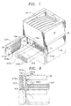
- each of the doors for example the doors 17 and 22 shown in section in Fig. 5, includes a guide chute 18, 23 respectively, comprising converging interior wall portions 18a, 18b and 23a, 23b respectively.
- the media guide chute 18 associated with the door 17 terminates in a slot 16 which mates with a converging slot extension 16a in part of the frame 45, and which houses the drive or pinch rollers 70a, 70b to urge media in the media guide path 30.
- the slot 21, underlying and aligned with the chute 18, is in the rack 44 associated with the tray 15.
- the slot 21 in a similar manner is aligned with a slot 21a also carrying drive or pinch rollers 60a, 60b , and aligned with the slot 21b formed by the converging sidewalls 23a, 23b of the chute 23.
- the slot 16a and 21a are sufficiently wide at their media entry points or mouths to embrace media entering from the bypass chutes 18 and 23 respectively, but also to permit media picked from the trays 15 and 20 to enter the slots 16a, 21a.
- the doors confronting the trays are swingable outwardly and away from the front of the trays, in the present instance trays 15,20 and 25.
- the doors are each hingeably attached, as by a hinge 19, to the frame 45 of the printer 10 (for simplification, only the hinge associated with the upper door 17 is shown, but the doors 22 and 27 may have similarly functional hinges.)
- the hinge 19 is vertically disposed, that is connected, in the example of Fig.
- spring biased latch means 36 are provided, remotely from the hinge 19, and adapted for entry into an aperture 37 in the frame of the printer 10 or the modular options. (The latch construction will be described in greater detail hereinafter with respect to Figs. 10 to 12.)
- doors 117, 122 are illustrated with associated media guide chutes 118 and 123 respectively, including converging interior walls 118a, 118b and 123a and 123b respectively.
- the trays 115,120 slidably engage parts of the frame 45 which act as racks for the media trays.
- each of the doors has a vertical extent which permits it to include the passive or idler rolls 170a, 160a of the pinch roll pairs 170a, 170b, and 160a, 160b respectively.
- the advantage of this configuration is that opening the door or doors confronting the media trays automatically effects uncoupling of the pinch rolls associated with the doors. This configuration is especially useful and helpful in clearing media jams between the media trays and the print engine.
- the door and tray form separable halves of the media guide means or chute allowing media stored below each tray to be fed past the superimposed media tray, into the media path 30 and then into the print engine.
- the printer 10 is shown with a single door 217 and tray 215, although it should be understood that there may be a number of similar doors and tray modules stacked below.
- the media guide means or chute 218 is formed or defined, when the door 217 is in the first or closed position, by spaced apart coaction between the confronting portions of the door 217 and tray 215.
- the ribs on both the door 217 and tray 215 are preferably tapered so as to be more narrow at their apex than at their roots so as to minimize contact and friction with the media passing through the chute 218.
- the door 217 may carry half of the pinch roll combination, i.e. idler roll 70a, the other or driver half 70b of the pinch rolls, being carried, as before, by the frame 45 of the printer or the modular options.
- a separate media guide or chute does not have to be provided for media bypass. Furthermore, when the door is opened, i.e. moved into a second position such as shown in Fig. 7, the chute formed intermediate the door and tray and the coupling between the pinch rolls is broken, releasing any media jam in either the guides or the rolls. Moreover, the condition of the media is immediately observable and if any difficulties are observed, may be easily corrected by the operator-user.
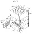
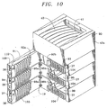
- a printer 90 is shown therein with multiple trays 93, 96, and 99 respectively, the trays being located in superimposed, overlapping relation to one another and supported within the printer casing 42a in a manner similar to that already described relative to Figs. 1 to 8.
- each of the doors and trays contain upstanding, tapered ribs 103, 104 defining a narrow converging media pass-through slot or chute therebetween.
- the ribs on both the doors 91,94,97, and the trays 93,96,99, are preferably tapered so as to be more narrow at their apex than at their roots so as to minimize contact and friction with the media passing through the chute defined therebetween.
- the doors may carry half of the pinch roll combination, i.e. the idler rolls 92a, 95a, and 98a respectively, the other or driver half 92b, 95b, and 98b of the pinch rolls, being carried, as before, by the frame 45 of the printer or the modular options.
- Each of the doors includes an end cap or cover 105 including finger-hole openings 106 to facilitate opening and closing individual ones of the doors, e.g. 91,94 and 97, the cover 105 being removed from door 94 to better view the latch mechanism as discussed and described below relative to Figs. 10 to 12.
- actuable coupling means for coupling each of the doors to its adjacent door, and thus to every other door, is provided and includes means for releasing the coupling means to permit opening of individual doors as desired.
- each door is provided with spaced apart pairs of rod segments 107,108 dimensioned for residing within the doors.
- the rod segments 107,108 of each of the doors 91,94 and 97 are aligned vertically with the rods of its adjacent door, when the doors are closed, through spaced apart, aligned apertures 109,110 in the top and bottom of each door.
- the segmented rods 107 and 108 are disposed within the doors, they are mounted for reciprocation between a first position with the rod segments disposed within the doors, and a second position with the rods in engagement with the adjacent door and in abutting aligned relation, end to end with the rod segments of adjacent doors so that the doors are coupled or ganged together for unitary operation.
- each of the doors includes a coupling disk 111 mounted for rotation as by an axle 112 adjacent each of the door ends, and having a pair of oppositely disposed camming slots 113, 114 therein for engagement with nibs or projections 115,116, respectively projecting from the segmented rods 107, 108.
- an actuator 120 Connected to the uppermost disk 111 and axle 112 is an actuator 120 comprising a handle 121, which as shown in Fig. 9, projects through the end cap or cover 105 of upper door 91.
- each door is provided with a latch 36 having a lobe portion 36a with frontal 38a and rear 38b camming surfaces.
- the latch passes through a slot 91a in the door frame.
- the frontal lobe portion 36a is connected to a shank portion 36b pivotally connected to a stub or projection 36c on the door.
- an actuator nib 108a on the rod 108 engages the latch shank portion 36b of each of the latches 36 and lifts the same for simultaneous latch release.
- the biasing spring 39 acts against the counterclockwise rotation of the handle 121 and serves as restoring force for reinsertion of the rods 107 and 108 into the normal or home position within each of the doors, as well as the actuator handle 121.
- the present invention provides media pass-through apparatus which avoids the inherent difficulties of the prior art. Moreover, the media pass-through apparatus of the present invention facilitates guidance of media from underlying media holding trays, while permitting ease of loading and unloading the same and clearing of incidental media jams in the media feed side of the print engine in the printer.
Landscapes
- Engineering & Computer Science (AREA)
- Mechanical Engineering (AREA)
- Sheets, Magazines, And Separation Thereof (AREA)
- Handling Of Cut Paper (AREA)
Claims (8)
- Mediendurchlassvorrichtung in einem Drucker, in die Medien von einer entfernbaren Medienablage (15) oder einem anderen Medienhalter durch einen Medienweg zu einer Druckmaschine (40) zugeführt wird, wobei die Vorrichtung umfasst:dadurch gekennzeichnet, dass sich die Türe (17) im Wesentlichen um einen Längsrand des Medienwegs zu der Druckmaschine (40) öffnet und schließt und dass eine von den Klemmrollen (70a) auf der Türe montiert ist und die andere Klemmrolle (70b) auf dem Rahmen (45) montiert ist.mindestens eine Medien tragende entfernbare Ablage oder einen anderen Medienhalter, der zur Platzierung unter der Druckmaschine konfiguriert ist;ein Gestell (44), das einen Teil eines Rahmens (45) bildet und zur Aufnahme der Ablage dimensioniert ist;eine Kombination aus Türe (17), Scharnier (19) und Falle (36), wobei das Scharnier zwischen der Türe und dem Rahmen verbunden ist, so dass sich die Türe nach außen und weg von der Vorderseite der Ablage öffnet, wobei die Falle entfernt von dem Scharnier positioniert ist, um die Türe bewegbar an dem Drucker anzubringen, und zwar in einer Stellung, in der sie der Ablage gegenüberliegt, wenn sich die Türe in einer geschlossenen oder ersten Stellung befindet, und offen ist, um eine Ablagenentfernung zu erleichtern, wenn sich die Türe in einer geöffneten oder zweiten Stellung befindet;eine Medienführungseinrichtung (18) auf der Innenseite der Türe, um verschiedene Medien vor der Ablage in den Medienführungsweg und zu der Druckmaschine zu führen;und ein Paar im Medienweg liegende Klemmrollen (70a, 70b), die im Eingriff miteinander stehen, wenn die Türe geschlossen ist;
- Vorrichtung nach Anspruch 1, bei der die Medienführungseinrichtung auf der Türe eine Rutsche (18) umfasst, die zusammenlaufende Innenwände (18a, 18b) darin aufweist, um Medien in einem vorbestimmten Weg hindurch zu zwingen.
- Vorrichtung nach Anspruch 1, bei der die Medienführungseinrichtung auf der Türe (117) eine erste (118a) von zwei zusammenlaufenden Innenwänden (118a, 118b) einer Rutsche (118) umfasst, wobei die zweite (118b) der Wände auf demjenigen Teil der Ablage (115) ausgebildet ist, welcher der Innenseite der Türe gegenüberliegt.
- Vorrichtung nach Anspruch 3, umfassend eine Mehrzahl von nach oben stehenden Rippen (218a, 218b) sowohl auf der Ablage (215) als auch dem gegenüberliegenden Teil (217) der Rutsche auf der Türe, welche die besagte Rutsche begrenzen.
- Vorrichtung nach Anspruch 4, bei der sich die Rippen zu Abschlussendteilen hin verjüngen, um eine Reibungsberührung mit dort hindurch tretenden Medien zu minimieren.
- Vorrichtung nach einem vorangehenden Anspruch, umfassend eine Mehrzahl der Medien tragenden Ablagen (93, 96, 99) in übereinanderliegender überlappender Beziehung, wobei mindestens einige der Ablagen eine besagte Kombination aus Türe (91, 94, 97), Scharnier und Falle (36) umfassen, die jeder besagten Ablage gegenüberliegt.
- Vorrichtung nach Anspruch 6, umfassend eine betätigbare Kopplungseinrichtung (107, 108), um jede der Türen (91, 94, 97) mit jeder anderen Türe zu koppeln, wenn es für ein gemeinsames Öffnen der Türen erwünscht ist, und Einrichtungen zur Freigabe der Kopplungseinrichtung (111), um ein Öffnen von einzelnen Türen zu ermöglichen, wenn gewünscht.
- Vorrichtung nach Anspruch 7, bei der die Kopplungseinrichtung ein Stangensegment (107, 108) umfasst, das für eine Hin- und Herbewegung in jeder von den Türen (91, 94, 96) angeordnet ist, und zwar zwischen einer ersten Stellung, in der sich das Stangensegment von jeder Türe innerhalb der Türe befindet, sowie einer zweiten Stellung, in der das Stangensegment in Eingriff mit einer benachbarten Türe angeordnet ist; wobei jedes von den Stangensegmenten fluchtet, wenn die Türen geschlossen sind, und Einrichtungen (113, 114), um die Stangensegmente in Eingriff zu bringen, um ein Stangensegment in einer Türe in Eingriff mit einer benachbarten Türe zu bringen, wodurch bei Betätigung die Türen gemeinsam zu öffnen und zu schließen sind, und bei Nichtbetätigung die Türen einzeln geöffnet werden können.
Applications Claiming Priority (2)
| Application Number | Priority Date | Filing Date | Title |
|---|---|---|---|
| US08/563,695 US5785308A (en) | 1995-11-28 | 1995-11-28 | Media pass through configuration for printers |
| US563695 | 1995-11-28 |
Publications (2)
| Publication Number | Publication Date |
|---|---|
| EP0776844A1 EP0776844A1 (de) | 1997-06-04 |
| EP0776844B1 true EP0776844B1 (de) | 2002-03-06 |
Family
ID=24251541
Family Applications (1)
| Application Number | Title | Priority Date | Filing Date |
|---|---|---|---|
| EP96308326A Expired - Lifetime EP0776844B1 (de) | 1995-11-28 | 1996-11-18 | Vorrichtung zum Durchführen von Auzeichnungsträgern in Druckern |
Country Status (4)
| Country | Link |
|---|---|
| US (1) | US5785308A (de) |
| EP (1) | EP0776844B1 (de) |
| JP (1) | JPH09235030A (de) |
| DE (1) | DE69619627T2 (de) |
Families Citing this family (24)
| Publication number | Priority date | Publication date | Assignee | Title |
|---|---|---|---|---|
| JPH10129860A (ja) * | 1996-10-31 | 1998-05-19 | Canon Inc | 記録装置 |
| US5975515A (en) * | 1997-02-21 | 1999-11-02 | Hewlett-Packard Company | System for designating paper cassettes in printers and copiers |
| EP0899227B1 (de) * | 1997-08-27 | 2004-10-20 | Sharp Kabushiki Kaisha | Blattzuführverfahren für ein Bilderzeugungsgerät, bei dem die Blatttransportbahn einer Blattkassette als Teil der Blatttransportbahn einer anderen Blattkassette dient |
| DE69816559T2 (de) * | 1997-10-24 | 2004-06-09 | Oki Data Corp. | Bildaufzeichnungsgerät |
| US6293540B1 (en) * | 1999-11-29 | 2001-09-25 | Diebold, Incorporated | Currency dispenser service method |
| US20050116407A1 (en) * | 2002-08-30 | 2005-06-02 | Fujitsu Limited | Paper sheets processor |
| JP2004107008A (ja) * | 2002-09-18 | 2004-04-08 | Fuji Xerox Co Ltd | シート搬送装置及び画像形成装置 |
| JP4029756B2 (ja) * | 2003-03-28 | 2008-01-09 | ブラザー工業株式会社 | 給紙装置、および、これを備えた画像形成装置 |
| JP2005099289A (ja) * | 2003-09-24 | 2005-04-14 | Fuji Xerox Co Ltd | プリンタ装置 |
| US20050093222A1 (en) * | 2003-10-29 | 2005-05-05 | Kabushiki Kaisha Toshiba | Sheet feeder in image forming apparatus |
| US7448734B2 (en) * | 2004-01-21 | 2008-11-11 | Silverbrook Research Pty Ltd | Inkjet printer cartridge with pagewidth printhead |
| US20050157112A1 (en) | 2004-01-21 | 2005-07-21 | Silverbrook Research Pty Ltd | Inkjet printer cradle with shaped recess for receiving a printer cartridge |
| TWI230125B (en) * | 2004-04-01 | 2005-04-01 | Benq Corp | Feeding box |
| US7613420B2 (en) * | 2005-02-23 | 2009-11-03 | Lexmark International, Inc. | Uniform entry of media into an alignment nip |
| JP4508992B2 (ja) * | 2005-09-13 | 2010-07-21 | キヤノン株式会社 | シート搬送装置及び画像形成装置 |
| US8028985B2 (en) * | 2008-08-08 | 2011-10-04 | Xerox Corporation | Composite substrate feeding mechanism |
| JP5545058B2 (ja) | 2010-06-17 | 2014-07-09 | ブラザー工業株式会社 | 画像記録装置 |
| US8025283B1 (en) * | 2010-10-29 | 2011-09-27 | Lexmark International, Inc. | Continuous media edge reference surface for a removable media input tray assembly of an image forming device |
| US20120304437A1 (en) * | 2011-05-31 | 2012-12-06 | Murray Richard A | Method of pivotable cleanout member |
| US8267393B1 (en) * | 2011-08-24 | 2012-09-18 | Lexmark International, Inc. | Continuous media edge reference surface for a removable media input tray assembly of an image forming device |
| JP2013043775A (ja) * | 2011-08-26 | 2013-03-04 | Seiko Epson Corp | 記録装置 |
| US9004485B2 (en) * | 2013-01-21 | 2015-04-14 | Hewlett-Packard Development Company, L.P. | Access door for media tray with rotational and translational movement of cleanout |
| JP5874779B2 (ja) * | 2014-05-14 | 2016-03-02 | ブラザー工業株式会社 | 画像記録装置 |
| JP6156525B2 (ja) * | 2016-01-21 | 2017-07-05 | ブラザー工業株式会社 | 画像記録装置 |
Family Cites Families (13)
| Publication number | Priority date | Publication date | Assignee | Title |
|---|---|---|---|---|
| US4531823A (en) * | 1981-04-17 | 1985-07-30 | Sanyo Electric Co., Ltd. | Electrostatic copying machine having removable paper path |
| JPS60197541A (ja) * | 1984-03-19 | 1985-10-07 | Ricoh Co Ltd | 転写紙供給装置 |
| US4966356A (en) * | 1987-09-30 | 1990-10-30 | Fujitsu Limited | Apparatus for selectively feeding cut sheets in a recording machine |
| CH678169A5 (de) * | 1988-03-07 | 1991-08-15 | Rutishauser Data Ag | |
| US4941002A (en) * | 1988-08-31 | 1990-07-10 | Seiko Epson Corporation | Page printer |
| JPH0734142B2 (ja) * | 1988-09-27 | 1995-04-12 | 三田工業株式会社 | 画像形成装置 |
| DE68917091T2 (de) * | 1988-11-22 | 1994-11-24 | Canon Kk | Bogenzuführvorrichtung. |
| JP3053021B2 (ja) * | 1990-03-19 | 2000-06-19 | 富士ゼロックス株式会社 | 画像形成装置 |
| KR940003112B1 (ko) * | 1991-10-25 | 1994-04-13 | 삼성전자 주식회사 | 전자사진방식을 이용한 기기에 사용되는 카세트 |
| US5263707A (en) * | 1992-03-09 | 1993-11-23 | Gradco (Japan) Ltd. | Combined stacker and sorter |
| JP2666104B2 (ja) * | 1992-09-16 | 1997-10-22 | 三田工業株式会社 | ペーパーカセットの支持装置 |
| JPH06107345A (ja) * | 1992-09-28 | 1994-04-19 | Ricoh Co Ltd | 給紙装置 |
| US5375826A (en) * | 1993-10-15 | 1994-12-27 | Lexmark International, Inc. | Paper tray control of a sheet feeder having biased nip rollers cooperative with the positioning of a paper tray |
-
1995
- 1995-11-28 US US08/563,695 patent/US5785308A/en not_active Expired - Lifetime
-
1996
- 1996-11-18 DE DE69619627T patent/DE69619627T2/de not_active Expired - Fee Related
- 1996-11-18 EP EP96308326A patent/EP0776844B1/de not_active Expired - Lifetime
- 1996-11-28 JP JP8332740A patent/JPH09235030A/ja active Pending
Also Published As
| Publication number | Publication date |
|---|---|
| EP0776844A1 (de) | 1997-06-04 |
| DE69619627D1 (de) | 2002-04-11 |
| JPH09235030A (ja) | 1997-09-09 |
| US5785308A (en) | 1998-07-28 |
| DE69619627T2 (de) | 2002-09-12 |
Similar Documents
| Publication | Publication Date | Title |
|---|---|---|
| EP0776844B1 (de) | Vorrichtung zum Durchführen von Auzeichnungsträgern in Druckern | |
| US4854757A (en) | Automatic sheet feeder movable between active and inactive positions | |
| US10301128B2 (en) | Sheet feed device and image recording apparatus having such sheet feed device | |
| US7481425B2 (en) | Paper feed cassette | |
| US4729681A (en) | Document processing device for single documents separable from a cross-perforated continuous form web | |
| JP2005099289A (ja) | プリンタ装置 | |
| WO1982001515A1 (en) | Selective paper insertion and feeding means for individual sheet printing apparatus | |
| JP2006082919A (ja) | 画像記録装置及びそれに適用する給紙トレイ | |
| JP2001232875A (ja) | プリンタ | |
| US7631865B2 (en) | Medium guide elevating device, recording apparatus and liquid ejecting apparatus | |
| US5340098A (en) | Single sheet supplier | |
| US20020164190A1 (en) | Imaging media tray loading access | |
| JP3734124B2 (ja) | シート収納マガジン | |
| JP2587598B2 (ja) | 給紙装置 | |
| JP2003001884A (ja) | プリンタ | |
| JP3248449B2 (ja) | プリンタ | |
| JPH09295750A (ja) | 用紙収容装置 | |
| JPH0679935A (ja) | 小型プリンタ | |
| JP2025030488A (ja) | 給送装置および画像形成装置 | |
| JPS62136437A (ja) | 印字装置 | |
| JPH0858995A (ja) | 給紙カセット | |
| JPH0555156U (ja) | 画像形成装置の記録紙カバー | |
| JPH0553697B2 (de) | ||
| JPH10291700A (ja) | ウエッブロール収納カセット | |
| JP2000116752A (ja) | 薬袋作成装置 |
Legal Events
| Date | Code | Title | Description |
|---|---|---|---|
| PUAI | Public reference made under article 153(3) epc to a published international application that has entered the european phase |
Free format text: ORIGINAL CODE: 0009012 |
|
| AK | Designated contracting states |
Kind code of ref document: A1 Designated state(s): DE FR GB |
|
| 17P | Request for examination filed |
Effective date: 19971124 |
|
| 17Q | First examination report despatched |
Effective date: 20000128 |
|
| GRAG | Despatch of communication of intention to grant |
Free format text: ORIGINAL CODE: EPIDOS AGRA |
|
| GRAG | Despatch of communication of intention to grant |
Free format text: ORIGINAL CODE: EPIDOS AGRA |
|
| GRAH | Despatch of communication of intention to grant a patent |
Free format text: ORIGINAL CODE: EPIDOS IGRA |
|
| GRAH | Despatch of communication of intention to grant a patent |
Free format text: ORIGINAL CODE: EPIDOS IGRA |
|
| REG | Reference to a national code |
Ref country code: GB Ref legal event code: IF02 |
|
| GRAA | (expected) grant |
Free format text: ORIGINAL CODE: 0009210 |
|
| AK | Designated contracting states |
Kind code of ref document: B1 Designated state(s): DE FR GB |
|
| REF | Corresponds to: |
Ref document number: 69619627 Country of ref document: DE Date of ref document: 20020411 |
|
| ET | Fr: translation filed | ||
| PLBE | No opposition filed within time limit |
Free format text: ORIGINAL CODE: 0009261 |
|
| STAA | Information on the status of an ep patent application or granted ep patent |
Free format text: STATUS: NO OPPOSITION FILED WITHIN TIME LIMIT |
|
| 26N | No opposition filed |
Effective date: 20021209 |
|
| PGFP | Annual fee paid to national office [announced via postgrant information from national office to epo] |
Ref country code: FR Payment date: 20061117 Year of fee payment: 11 |
|
| PGFP | Annual fee paid to national office [announced via postgrant information from national office to epo] |
Ref country code: GB Payment date: 20061122 Year of fee payment: 11 |
|
| PGFP | Annual fee paid to national office [announced via postgrant information from national office to epo] |
Ref country code: DE Payment date: 20070102 Year of fee payment: 11 |
|
| GBPC | Gb: european patent ceased through non-payment of renewal fee |
Effective date: 20071118 |
|
| PG25 | Lapsed in a contracting state [announced via postgrant information from national office to epo] |
Ref country code: DE Free format text: LAPSE BECAUSE OF NON-PAYMENT OF DUE FEES Effective date: 20080603 |
|
| REG | Reference to a national code |
Ref country code: FR Ref legal event code: ST Effective date: 20080930 |
|
| PG25 | Lapsed in a contracting state [announced via postgrant information from national office to epo] |
Ref country code: GB Free format text: LAPSE BECAUSE OF NON-PAYMENT OF DUE FEES Effective date: 20071118 |
|
| PG25 | Lapsed in a contracting state [announced via postgrant information from national office to epo] |
Ref country code: FR Free format text: LAPSE BECAUSE OF NON-PAYMENT OF DUE FEES Effective date: 20071130 |