EP0777031A1 - Rafflamellenstore - Google Patents
Rafflamellenstore Download PDFInfo
- Publication number
- EP0777031A1 EP0777031A1 EP96116534A EP96116534A EP0777031A1 EP 0777031 A1 EP0777031 A1 EP 0777031A1 EP 96116534 A EP96116534 A EP 96116534A EP 96116534 A EP96116534 A EP 96116534A EP 0777031 A1 EP0777031 A1 EP 0777031A1
- Authority
- EP
- European Patent Office
- Prior art keywords
- eyelet
- web
- section
- staple
- articulated
- Prior art date
- Legal status (The legal status is an assumption and is not a legal conclusion. Google has not performed a legal analysis and makes no representation as to the accuracy of the status listed.)
- Granted
Links
- 241000309551 Arthraxon hispidus Species 0.000 claims description 12
- 241000446313 Lamella Species 0.000 claims description 4
- 238000004519 manufacturing process Methods 0.000 description 4
- 238000000034 method Methods 0.000 description 2
- 238000005452 bending Methods 0.000 description 1
- 238000003780 insertion Methods 0.000 description 1
- 230000037431 insertion Effects 0.000 description 1
- 238000007493 shaping process Methods 0.000 description 1
- 229910001220 stainless steel Inorganic materials 0.000 description 1
- 239000010935 stainless steel Substances 0.000 description 1
Images

Classifications
-
- A—HUMAN NECESSITIES
- A47—FURNITURE; DOMESTIC ARTICLES OR APPLIANCES; COFFEE MILLS; SPICE MILLS; SUCTION CLEANERS IN GENERAL
- A47H—FURNISHINGS FOR WINDOWS OR DOORS
- A47H23/00—Curtains; Draperies
- A47H23/02—Shapes of curtains; Selection of particular materials for curtains
- A47H23/04—Shapes of curtains
- A47H23/05—Shapes of curtains of chain or chain mail; of free-hanging strips or lamellae
-
- E—FIXED CONSTRUCTIONS
- E06—DOORS, WINDOWS, SHUTTERS, OR ROLLER BLINDS IN GENERAL; LADDERS
- E06B—FIXED OR MOVABLE CLOSURES FOR OPENINGS IN BUILDINGS, VEHICLES, FENCES OR LIKE ENCLOSURES IN GENERAL, e.g. DOORS, WINDOWS, BLINDS, GATES
- E06B9/00—Screening or protective devices for wall or similar openings, with or without operating or securing mechanisms; Closures of similar construction
- E06B9/24—Screens or other constructions affording protection against light, especially against sunshine; Similar screens for privacy or appearance; Slat blinds
- E06B9/26—Lamellar or like blinds, e.g. venetian blinds
- E06B9/38—Other details
- E06B9/384—Details of interconnection or interaction of tapes and lamellae
Definitions
- the present invention relates to a roman blinds according to the preamble of claim 1 and to a connecting element according to the preamble of claim 7.
- the object of the invention is therefore to create a slat blind of the type mentioned at the outset or a connecting element for an articulated connection, on which or with which the aforementioned conditions can be met better than with all previously known solutions.
- FIGS. 1 and 2 which is shown in detail in FIGS. 1 and 2, has slats 1 with flanged longitudinal edges 2, 3, which are connected to the carrying straps 5 of the store by articulated connections 4.
- the slats 1 are fastened with their longitudinal edges 2, 3 to at least two carrying bands 5 each.
- the articulated connection 4 has an articulated head 6, which is connected by means of a neck 7 to a cuboid body 8, which is molded onto the support band 5.
- the joint head 6, the neck 7 and the body 8 are made in one piece from plastic and molded onto the carrier tape 5 in one operation.
- a connecting element 9 also belongs to the articulated connection 4.
- This connecting element 9 consists of a staple-like section with two legs 11 connected by a web 10, each with a predetermined bending point 12, and of an eyelet 13 arranged in the longitudinal center of the web 10 and made in one piece with it Eyelet 13 is bent around a straight line 14 (FIGS. 4 and 5) parallel to the flange 2, 3.
- the arc 15 of the eyelet 13 formed in this way bulges in the horizontal slat position (FIG. 2) on the outside of the blind A upwards and on the inside of the blind I downwards.
- the eyelet 13 is pierced by a slot 16, the length of which is dimensioned such that the joint head 6 trapped therein can be pivoted about the straight line 14 by at least 90 °.
- the slats can be pivoted between a horizontal open position and a substantially vertical closed position, in which they darken a room, by means of the carrying straps 5 suspended on the pivoting or rocking device of the store.
- the width of the slot 16 is smaller than the diameter of the joint head 6, so that it is caught in the eye 13 in all pivot positions.
- a flat stamped part (FIG. 3) is initially made of stainless steel.
- the slot 16 of the eyelet 13 widens from the width "a" to the width "b” with increasing distance from the web 10.
- the smallest width "a” of the slot 16 is larger than the diameter of the neck 7 carrying the joint head 6 (FIG. 1) and smaller than the diameter of the joint head 6; the greatest width "b", on the other hand, is larger than the diameter of the joint head 6.
- the eyelet 13 is semicircular in a subsequent operation around a lying in the plane of the legs 11 and the web 10 and to the web 10 parallel straight line 14 bent (Fig. 4 and 5).
- the connecting element 9 is ready for use in the manufacturing process of the Roman blind store.
- the connecting element 9 is shot by the driver of a stapler with the legs 11 ahead through the lamella flange 2, 3 against the bender of the stapler.
- the legs 11 bend in the middle because of the predetermined kink 12 and positively embrace the adjacent wall sections of the flanges 2, 3 (FIG. 6).
- an articulated head 6, which is firmly connected to a carrier tape 5 is pushed through the slot 16 and the eyelet 13 is then pressed together with a pair of pliers in the area of the largest slot width "b" (FIG. 7, arrows 18).
- the slot 16 is brought uniformly over its entire length to the smallest slot width "a" (FIG. 7) and the joint head 6 is caught. This can now be pivoted through 90 ° in the eyelet 13 (FIG. 4), as a result of which the lamella 1 receives the pivotability between a horizontal open position and a closed position already mentioned with reference to FIG. 2.
Landscapes
- Engineering & Computer Science (AREA)
- Structural Engineering (AREA)
- Architecture (AREA)
- Civil Engineering (AREA)
- Blinds (AREA)
- Control Of The Air-Fuel Ratio Of Carburetors (AREA)
- Looms (AREA)
Abstract
Description
- Die vorliegende Erfindung bezieht sich auf einen Rafflamellenstore gemäss dem Oberbegriff des Anspruchs 1 und auf ein Verbindungselement gemäss dem Oberbegriff des Anspruchs 7.
- Bei Rafflamellenstores ist es bekannt, die Lamellen mittels Gelenkverbindungen an den Tragsträngen zu befestigen. Nebst einer langen Lebensdauer werden an diese Gelenkverbindungen noch weitere Anforderungen gestellt. Zum einen müssen der Gelenkkopf und die Gelenkpfanne kostengünstig herstellbar und ebenso kostengünstig an den Tragsträngen bzw. den Lamellen montierbar sein. Hinsichtlich der Montage muss die Gelenkverbindung zudem die Möglichkeit bieten, die einzelnen Vorgänge mit einfachen Mitteln mechanisieren und automatisieren zu können, damit die Verwendung der Gelenkverbindung sowohl in der Klein- als auch in der Grossserienfertigung möglich ist.
- Die Erfindung stellt sich daher die Aufgabe, einen Lamellenstore der eingangs erwähnten Art bzw. ein Verbindungselement für eine Gelenkverbindung zu schaffen, an dem bzw. mit dem die vorerwähnten Bedingungen besser als mit allen bisher bekannten Lösungen erfüllbar sind.
- Erfindungsgemäss wird diese Aufgabe gelöst durch die kennzeichnenden Merkmale der Ansprüche 1 und 7.
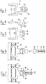
- Anhand der beiliegenden schematischen Zeichnung wird die Erfindung beispielsweise erläutert. Es zeigen:
- Fig. 1
- eine perspektivische Ansicht einer Gelenkverbindung zwischen dem Tragstrang eines Rafflamellenstores und der Längsseite einer Lamelle,
- Fig. 2
- einen Querschnitt durch eine Lamelle eines Rafflamellenstores mit zwei sich gegenüberliegenden Gelenkverbindungen,
- Fig. 3
- eine Draufsicht auf ein einen Gelenkkopfkäfig bildendes Verbindungsteil in Abwinklung,
- Fig. 4
- eine Seitenansicht eines Verbindungsteils vor dessen Befestigung an einer Lamelle,
- Fig. 5
- eine Draufsicht auf das Verbindungsteil in Fig. 4,
- Fig. 6
- einen Längsschnitt durch einen Lamellenbördel mit einem daran befestigten Verbindungselement vor dem Einsetzen des Gelenkkopfes,
- Fig. 7
- eine gleiche Darstellung wie Fig. 6 nach dem Einsetzen des Gelenkkopfes.
- Der in den Fig. 1 und 2 ausschnittsweise gezeigte Rafflamellenstore weist Lamellen 1 mit gebördelten Längsrändern 2, 3 auf, die durch Gelenkverbindungen 4 mit den Tragbändern 5 des Stores verbunden sind. Die Lamellen 1 sind mit ihren Längsrändern 2, 3 je an mindestens zwei Tragbändern 5 befestigt.
- Die Gelenkverbindung 4 weist einen Gelenkkopf 6 auf, der mittels eines Halses 7 mit einem quaderförmigen, am Tragband 5 angespritzten Körper 8 verbunden ist. Der Gelenkkopf 6, der Hals 7 und der Körper 8 sind aus Kunststoff einstückig gefertigt und in einem Arbeitsgang an das Tragband 5 angespritzt.
- Weiter gehört zur Gelenkverbindung 4 ein Verbindungselement 9. Dieses Verbindungselement 9 besteht aus einem heftklammerartigen Abschnitt mit zwei durch einen Steg 10 verbundenen Schenkeln 11 mit je einer Sollknickstelle 12 und aus einer in der Längsmitte des Steges 10 angeordneten und mit ihm einstückig gefertigten Öse 13. Die Öse 13 ist um eine zum Bördel 2, 3 parallele Gerade 14 (Fig. 4 und 5) U-förmig gebogen. Der hierdurch gebildete Bogen 15 der Öse 13 wölbt sich bei horizontaler Lamellenlage (Fig. 2) auf der Storenaussenseite A nach oben und auf der Storeninnenseite I nach unten. Weiter ist die Öse 13 von einem Schlitz 16 durchbrochen, dessen Länge so bemessen ist, dass der darin gefangene Gelenkkopf 6 um mindestens 90° um die Gerade 14 verschwenkt werden kann.
- Dadurch können die Lamellen mittels den an der Schwenk- bzw. Wippeinrichtung des Stores aufgehängten Tragbändern 5 zwischen einer horizontalen Offenstellung und einer im wesentlichen senkrechten Schliessstellung, in der sie einen Raum abdunkeln, verschwenkt werden.
- Die Breite des Schlitzes 16 ist kleiner als der Durchmesser des Gelenkkopfes 6, so dass er in allen Schwenklagen in der Öse 13 gefangen ist.
- Bei der Herstellung des Verbindungselementes 9 wird vorerst ein Flachstanzteil (Fig. 3) aus rostfreiem Stahl hergestellt. Bei diesem Flachstanzteil verbreitert sich der Schlitz 16 der Öse 13 mit zunehmendem Abstand vom Steg 10 von der Breite "a" auf die Breite "b". Die kleinste Breite "a" des Schlitzes 16 ist grösser als der Durchmesser des den Gelenkkopf 6 tragenden Halses 7 (Fig. 1) und kleiner als der Durchmesser des Gelenkkopfes 6; die grösste Breite "b" dagegen ist grösser als der Durchmesser des Gelenkkopfes 6. An diesem Flachstanzteil (Fig. 3) wird in einem nachfolgenden Arbeitsgang die Öse 13 halbkreisförmig um eine in der Ebene der Schenkel 11 und des Steges 10 liegende und zum Steg 10 parallele Gerade 14 gebogen (Fig. 4 und 5). Nach diesem Formgebungsschritt ist das Verbindungselement 9 bereit für den Einsatz im Fertigungsprozess des Rafflamellenstores. Dort wird das Verbindungselement 9 vom Treiber eines Heftapparates mit den Schenkeln 11 voraus durch den Lamellenbördel 2, 3 hindurch gegen den Umbieger des Heftapparates geschossen. Während dieses Heftvorganges knicken die Schenkel 11 wegen der Sollknickstelle 12 mittig ein und umgreifen formschlüssig die angrenzenden Wandabschnitte der Bördel 2, 3 (Fig. 6). Danach wird ein mit einem Tragband 5 fest verbundener Gelenkkopf 6 durch den Schlitz 16 hindurch geschoben und anschliessend die Öse 13 im Bereich der grössten Schlitzbreite "b" mit einer Zange zusammengedrückt (Fig. 7, Pfeile 18). Dabei wird der Schlitz 16 über seine ganze Länge gleichmässig auf die kleinste Schlitzbreite "a" gebracht (Fig. 7) und der Gelenkkopf 6 gefangen. Dieser kann nun in der Öse 13 um 90° verschwenkt werden (Fig. 4), wodurch die Lamelle 1, die mit Bezug auf die Fig. 2 bereits erwähnte Verschwenkbarkeit zwischen einer horizontalen Offenstellung und einer Schliessstellung erhält.
Claims (13)
- Rafflamellenstore mit Tragsträngen (5), die mit den Lamellen (1) durch Gelenkverbindungen (4) an den Lamellenlängsseiten verbunden sind, wobei der Gelenkkopf (6) jeder Gelenkverbindung (4) am Tragstrang (5) und das die Gelenkpfanne bildende Verbindungselement (9) an der Lamelle (1) angeordnet ist, dadurch gekennzeichnet, dass das Verbindungselement (9) einen heftklammerartigen Abschnitt (10, 11) aufweist, der mit einer daran angeordneten Öse (13) den Gelenkkopf (6) gefangen hält.
- Rafflamellenstore nach Anspruch 1, dadurch gekennzeichnet, dass der heftklammerartige Abschnitt (10, 11) und die Öse (13) einstückig gefertigt sind.
- Rafflamellenstore nach Anspruch 1 oder 2, dadurch gekennzeichnet, dass der heftklammerartige Abschnitt (10, 11) zwei durch einen Steg (10) verbundene Schenkel (11) aufweist, wobei die Öse (13) in der Stegmitte vorgesehen ist.
- Rafflamellenstore nach einem der Ansprüche 1 bis 3, dadurch gekennzeichnet, dass die Öse (13) um eine zum Steg (10) parallele Gerade (14) U-förmig umgebogen ist.
- Rafflamellenstore nach Anspruch 4, dadurch gekennzeichnet, dass der Bogen (15) der Öse (13) auf einer Lamellenlängsseite nach oben und auf der anderen Lamellenlängsseite nach unten weist.
- Rafflamellenstore nach Anspruch 4, dadurch gekennzeichnet, dass die Öse (13) eine schlitzförmige Durchbrechung (16) bildet, die in Längsrichtung gesehen kreisbogenartig um die Gerade (14) über einen Winkel von mindestens 90° verläuft.
- Verbindungselement für eine Gelenkverbindung zum Verbinden der Lamellenlängsseite eines Rafflamellenstores mit einem seiner Tragstränge (5), wobei der Gelenkkopf (6) der Gelenkverbindung am Tragstrang (5) angeordnet ist und das Verbindungselement (9) eine Gelenkpfanne für den Gelenkkopf (6) bildet, dadurch gekennzeichnet, dass das Verbindungselement (9) einen heftklammerartigen Abschnitt (10, 11) aufweist, der mit einer daran angeordneten Öse (13) eine einen Gelenkkopf (6) hintergreifende Gelenkpfanne bildet.
- Verbindungsteil nach Anspruch 7, dadurch gekennzeichnet, dass der heftklammerartige Abschnitt (10, 11) und die Öse (13) einstückig gefertigt sind.
- Verbindungsteil nach Anspruch 7 oder 8, dadurch gekennzeichnet, dass der heftklammerartige Abschnitt (10, 11) zwei durch einen Steg (10) verbundene Schenkel (11) aufweist, wobei die Öse (13) im wesentlichen in deer Stegmitte vorgesehen ist.
- Verbindungsteil nach einem der Ansprüche 7 bis 9, dadurch gekennzeichnet, dass die Öse (13) um eine zum Steg (10) parallele Gerade (14) U-förmig gebogen ist.
- Verbindungsteil nach Anspruch 10, dadurch gekennzeichnet, dass die Öse (13) einen Schlitz (16) aufweist, der sich kreisbogenartig über einen Winkel von mindestens 90° um die Gerade (14) erstreckt.
- Verbindungsteil nach Anspruch 11, dadurch gekennzeichnet, dass die Breite (a, b) des Schlitzes (16) mit zunehmendem Abstand vom Steg (10) grösser wird.
- Verbindungsteil nach einem der Ansprüche 7 bis 12, dadurch gekennzeichnet, dass die Schenkel (11) des heftklammerartigen Abschnitts (10, 11) mit Sollknickstellen (12) versehen sind.
Applications Claiming Priority (3)
| Application Number | Priority Date | Filing Date | Title |
|---|---|---|---|
| CH03371/95A CH690454A5 (de) | 1995-11-28 | 1995-11-28 | Rafflamellenstore. |
| CH3371/95 | 1995-11-28 | ||
| CH337195 | 1995-11-28 |
Publications (2)
| Publication Number | Publication Date |
|---|---|
| EP0777031A1 true EP0777031A1 (de) | 1997-06-04 |
| EP0777031B1 EP0777031B1 (de) | 2001-09-19 |
Family
ID=4254522
Family Applications (1)
| Application Number | Title | Priority Date | Filing Date |
|---|---|---|---|
| EP96116534A Expired - Lifetime EP0777031B1 (de) | 1995-11-28 | 1996-10-16 | Rafflamellenstore |
Country Status (4)
| Country | Link |
|---|---|
| EP (1) | EP0777031B1 (de) |
| AT (1) | ATE205912T1 (de) |
| CH (1) | CH690454A5 (de) |
| DE (2) | DE29617915U1 (de) |
Cited By (2)
| Publication number | Priority date | Publication date | Assignee | Title |
|---|---|---|---|---|
| CH707481A1 (de) * | 2013-01-22 | 2014-07-31 | Griesser Holding Ag | Vorrichtung zum gelenkigen Verbinden von Lamellen mit Tragorganen eines Rafflamellenstorens. |
| CH711490A1 (de) * | 2015-09-03 | 2017-03-15 | Griesser Holding Ag | Vorrichtung zur Stabilisierung von Lamellenstoren. |
Families Citing this family (2)
| Publication number | Priority date | Publication date | Assignee | Title |
|---|---|---|---|---|
| AT505292B1 (de) * | 2007-06-21 | 2008-12-15 | Kraler Franz | Rafflamellenstore |
| AT505405B1 (de) * | 2007-06-21 | 2009-01-15 | Kraler Franz | Rafflamellenstore |
Citations (3)
| Publication number | Priority date | Publication date | Assignee | Title |
|---|---|---|---|---|
| CH639725A5 (en) * | 1982-01-08 | 1983-11-30 | Storenmaterial Ag | Venetian blind |
| EP0101809A2 (de) * | 1982-08-27 | 1984-03-07 | Griesser A.G. | Rafflamellenstore |
| EP0278266A1 (de) * | 1987-02-06 | 1988-08-17 | Huber & Co. AG Bandfabrik | Gelenkverbindung und Verwendung derselben |
-
1995
- 1995-11-28 CH CH03371/95A patent/CH690454A5/de not_active IP Right Cessation
-
1996
- 1996-10-15 DE DE29617915U patent/DE29617915U1/de not_active Expired - Lifetime
- 1996-10-16 DE DE59607715T patent/DE59607715D1/de not_active Expired - Lifetime
- 1996-10-16 EP EP96116534A patent/EP0777031B1/de not_active Expired - Lifetime
- 1996-10-16 AT AT96116534T patent/ATE205912T1/de active
Patent Citations (3)
| Publication number | Priority date | Publication date | Assignee | Title |
|---|---|---|---|---|
| CH639725A5 (en) * | 1982-01-08 | 1983-11-30 | Storenmaterial Ag | Venetian blind |
| EP0101809A2 (de) * | 1982-08-27 | 1984-03-07 | Griesser A.G. | Rafflamellenstore |
| EP0278266A1 (de) * | 1987-02-06 | 1988-08-17 | Huber & Co. AG Bandfabrik | Gelenkverbindung und Verwendung derselben |
Cited By (2)
| Publication number | Priority date | Publication date | Assignee | Title |
|---|---|---|---|---|
| CH707481A1 (de) * | 2013-01-22 | 2014-07-31 | Griesser Holding Ag | Vorrichtung zum gelenkigen Verbinden von Lamellen mit Tragorganen eines Rafflamellenstorens. |
| CH711490A1 (de) * | 2015-09-03 | 2017-03-15 | Griesser Holding Ag | Vorrichtung zur Stabilisierung von Lamellenstoren. |
Also Published As
| Publication number | Publication date |
|---|---|
| CH690454A5 (de) | 2000-09-15 |
| ATE205912T1 (de) | 2001-10-15 |
| DE29617915U1 (de) | 1996-12-05 |
| DE59607715D1 (de) | 2001-10-25 |
| EP0777031B1 (de) | 2001-09-19 |
Similar Documents
| Publication | Publication Date | Title |
|---|---|---|
| DE3318681A1 (de) | Stabjalousie | |
| CH621652A5 (de) | ||
| EP2163408A1 (de) | Gleitzschutzkette | |
| DE602005001846T2 (de) | Zum stützen und führen von kleidung in hängefördersystemen verwendetes band mit öffnungen | |
| EP0842096A1 (de) | Magazinierbarer streifen von verschlussklammern für schläuche und beutel | |
| EP0777031B1 (de) | Rafflamellenstore | |
| DE2734887A1 (de) | Rafflamellenstore | |
| EP0179968B1 (de) | Rafflamellenstore | |
| EP0389831A2 (de) | Vorrichtung zum Binden langgestreckter Gegenstände | |
| DE70451C (de) | Rollvorhang mit in der Breiten-Richtung gekrümmten Querscbienen | |
| DE2919582C2 (de) | ||
| DE7617071U1 (de) | Aufhaengevorrichtung fuer langgestreckte gegenstaende | |
| EP0081792A2 (de) | Gleitschutzkette für Fahrzeugräder | |
| DE3218714C2 (de) | Stator für Exzenterschneckenpumpen | |
| CH654374A5 (de) | Tragelement fuer eine rafflamellenstore. | |
| DE2212894A1 (de) | Rafflamellenjalousie mit trag und wendeschnueren | |
| EP0278266B1 (de) | Gelenkverbindung und Verwendung derselben | |
| DE19711818B4 (de) | Kraftfahrzeug mit einer beim Öffnen nach oben verschwenkbaren Hecktür | |
| EP2006482A2 (de) | Rafflamellenstore | |
| DE8236059U1 (de) | Anschluß- und Abspannarmatur für Linearelemente, insbesondere für elektrische Kabel u. dgl. | |
| CH671737A5 (de) | ||
| DE2344667A1 (de) | Fuehrungsvorrichtung zur festlegung und rangierung von leitungen | |
| DE10037903C2 (de) | Verbindungselement zum Anschluß von über die Lauffläche einer Reifenkette verlaufenden Kettenstrangabschnitten | |
| DE29602310U1 (de) | Aufhängevorrichtung für einen senkrecht angeordneten Vorhangstreifen | |
| DE202025102378U1 (de) | Rankgerüst |
Legal Events
| Date | Code | Title | Description |
|---|---|---|---|
| PUAI | Public reference made under article 153(3) epc to a published international application that has entered the european phase |
Free format text: ORIGINAL CODE: 0009012 |
|
| AK | Designated contracting states |
Kind code of ref document: A1 Designated state(s): AT CH DE FR GB IT LI |
|
| 17P | Request for examination filed |
Effective date: 19970619 |
|
| 17Q | First examination report despatched |
Effective date: 19990924 |
|
| GRAG | Despatch of communication of intention to grant |
Free format text: ORIGINAL CODE: EPIDOS AGRA |
|
| GRAG | Despatch of communication of intention to grant |
Free format text: ORIGINAL CODE: EPIDOS AGRA |
|
| GRAH | Despatch of communication of intention to grant a patent |
Free format text: ORIGINAL CODE: EPIDOS IGRA |
|
| GRAH | Despatch of communication of intention to grant a patent |
Free format text: ORIGINAL CODE: EPIDOS IGRA |
|
| GRAA | (expected) grant |
Free format text: ORIGINAL CODE: 0009210 |
|
| AK | Designated contracting states |
Kind code of ref document: B1 Designated state(s): AT CH DE FR GB IT LI |
|
| REF | Corresponds to: |
Ref document number: 205912 Country of ref document: AT Date of ref document: 20011015 Kind code of ref document: T |
|
| ITF | It: translation for a ep patent filed | ||
| REG | Reference to a national code |
Ref country code: CH Ref legal event code: NV Representative=s name: ISLER & PEDRAZZINI AG Ref country code: CH Ref legal event code: EP |
|
| GBT | Gb: translation of ep patent filed (gb section 77(6)(a)/1977) |
Effective date: 20010919 |
|
| REF | Corresponds to: |
Ref document number: 59607715 Country of ref document: DE Date of ref document: 20011025 |
|
| ET | Fr: translation filed | ||
| REG | Reference to a national code |
Ref country code: GB Ref legal event code: IF02 |
|
| PLBE | No opposition filed within time limit |
Free format text: ORIGINAL CODE: 0009261 |
|
| STAA | Information on the status of an ep patent application or granted ep patent |
Free format text: STATUS: NO OPPOSITION FILED WITHIN TIME LIMIT |
|
| 26N | No opposition filed | ||
| REG | Reference to a national code |
Ref country code: CH Ref legal event code: PCAR Free format text: ISLER & PEDRAZZINI AG;POSTFACH 1772;8027 ZUERICH (CH) |
|
| REG | Reference to a national code |
Ref country code: FR Ref legal event code: PLFP Year of fee payment: 20 |
|
| PGFP | Annual fee paid to national office [announced via postgrant information from national office to epo] |
Ref country code: CH Payment date: 20151012 Year of fee payment: 20 Ref country code: IT Payment date: 20151026 Year of fee payment: 20 Ref country code: GB Payment date: 20151021 Year of fee payment: 20 Ref country code: DE Payment date: 20151022 Year of fee payment: 20 |
|
| PGFP | Annual fee paid to national office [announced via postgrant information from national office to epo] |
Ref country code: AT Payment date: 20151022 Year of fee payment: 20 Ref country code: FR Payment date: 20151023 Year of fee payment: 20 |
|
| REG | Reference to a national code |
Ref country code: DE Ref legal event code: R071 Ref document number: 59607715 Country of ref document: DE |
|
| REG | Reference to a national code |
Ref country code: CH Ref legal event code: PL |
|
| REG | Reference to a national code |
Ref country code: GB Ref legal event code: PE20 Expiry date: 20161015 |
|
| REG | Reference to a national code |
Ref country code: AT Ref legal event code: MK07 Ref document number: 205912 Country of ref document: AT Kind code of ref document: T Effective date: 20161016 |
|
| PG25 | Lapsed in a contracting state [announced via postgrant information from national office to epo] |
Ref country code: GB Free format text: LAPSE BECAUSE OF EXPIRATION OF PROTECTION Effective date: 20161015 |