EP0777128A1 - Verfahren und Gerät zur Lagemessung eines Satelliten - Google Patents
Verfahren und Gerät zur Lagemessung eines Satelliten Download PDFInfo
- Publication number
- EP0777128A1 EP0777128A1 EP96402579A EP96402579A EP0777128A1 EP 0777128 A1 EP0777128 A1 EP 0777128A1 EP 96402579 A EP96402579 A EP 96402579A EP 96402579 A EP96402579 A EP 96402579A EP 0777128 A1 EP0777128 A1 EP 0777128A1
- Authority
- EP
- European Patent Office
- Prior art keywords
- attitude
- satellite
- gps
- measurement
- antennas
- Prior art date
- Legal status (The legal status is an assumption and is not a legal conclusion. Google has not performed a legal analysis and makes no representation as to the accuracy of the status listed.)
- Granted
Links
Images

Classifications
-
- G—PHYSICS
- G01—MEASURING; TESTING
- G01S—RADIO DIRECTION-FINDING; RADIO NAVIGATION; DETERMINING DISTANCE OR VELOCITY BY USE OF RADIO WAVES; LOCATING OR PRESENCE-DETECTING BY USE OF THE REFLECTION OR RERADIATION OF RADIO WAVES; ANALOGOUS ARRANGEMENTS USING OTHER WAVES
- G01S19/00—Satellite radio beacon positioning systems; Determining position, velocity or attitude using signals transmitted by such systems
- G01S19/38—Determining a navigation solution using signals transmitted by a satellite radio beacon positioning system
- G01S19/39—Determining a navigation solution using signals transmitted by a satellite radio beacon positioning system the satellite radio beacon positioning system transmitting time-stamped messages, e.g. GPS [Global Positioning System], GLONASS [Global Orbiting Navigation Satellite System] or GALILEO
- G01S19/53—Determining attitude
- G01S19/54—Determining attitude using carrier phase measurements; using long or short baseline interferometry
-
- B—PERFORMING OPERATIONS; TRANSPORTING
- B64—AIRCRAFT; AVIATION; COSMONAUTICS
- B64G—COSMONAUTICS; VEHICLES OR EQUIPMENT THEREFOR
- B64G1/00—Cosmonautic vehicles
- B64G1/22—Parts of, or equipment specially adapted for fitting in or to, cosmonautic vehicles
- B64G1/24—Guiding or controlling apparatus, e.g. for attitude control
- B64G1/244—Spacecraft control systems
-
- G—PHYSICS
- G01—MEASURING; TESTING
- G01S—RADIO DIRECTION-FINDING; RADIO NAVIGATION; DETERMINING DISTANCE OR VELOCITY BY USE OF RADIO WAVES; LOCATING OR PRESENCE-DETECTING BY USE OF THE REFLECTION OR RERADIATION OF RADIO WAVES; ANALOGOUS ARRANGEMENTS USING OTHER WAVES
- G01S19/00—Satellite radio beacon positioning systems; Determining position, velocity or attitude using signals transmitted by such systems
- G01S19/01—Satellite radio beacon positioning systems transmitting time-stamped messages, e.g. GPS [Global Positioning System], GLONASS [Global Orbiting Navigation Satellite System] or GALILEO
- G01S19/13—Receivers
- G01S19/14—Receivers specially adapted for specific applications
-
- G—PHYSICS
- G01—MEASURING; TESTING
- G01S—RADIO DIRECTION-FINDING; RADIO NAVIGATION; DETERMINING DISTANCE OR VELOCITY BY USE OF RADIO WAVES; LOCATING OR PRESENCE-DETECTING BY USE OF THE REFLECTION OR RERADIATION OF RADIO WAVES; ANALOGOUS ARRANGEMENTS USING OTHER WAVES
- G01S19/00—Satellite radio beacon positioning systems; Determining position, velocity or attitude using signals transmitted by such systems
- G01S19/01—Satellite radio beacon positioning systems transmitting time-stamped messages, e.g. GPS [Global Positioning System], GLONASS [Global Orbiting Navigation Satellite System] or GALILEO
- G01S19/13—Receivers
- G01S19/23—Testing, monitoring, correcting or calibrating of receiver elements
-
- G—PHYSICS
- G01—MEASURING; TESTING
- G01S—RADIO DIRECTION-FINDING; RADIO NAVIGATION; DETERMINING DISTANCE OR VELOCITY BY USE OF RADIO WAVES; LOCATING OR PRESENCE-DETECTING BY USE OF THE REFLECTION OR RERADIATION OF RADIO WAVES; ANALOGOUS ARRANGEMENTS USING OTHER WAVES
- G01S3/00—Direction-finders for determining the direction from which infrasonic, sonic, ultrasonic or electromagnetic waves, or particle emission, not having a directional significance, are being received
- G01S3/78—Direction-finders for determining the direction from which infrasonic, sonic, ultrasonic or electromagnetic waves, or particle emission, not having a directional significance, are being received using electromagnetic waves other than radio waves
- G01S3/782—Systems for determining direction or deviation from predetermined direction
- G01S3/785—Systems for determining direction or deviation from predetermined direction using adjustment of orientation of directivity characteristics of a detector or detector system to give a desired condition of signal derived from that detector or detector system
- G01S3/786—Systems for determining direction or deviation from predetermined direction using adjustment of orientation of directivity characteristics of a detector or detector system to give a desired condition of signal derived from that detector or detector system the desired condition being maintained automatically
- G01S3/7867—Star trackers
Definitions
- the present invention relates to a device and a method for measuring the attitude of a terrestrial satellite in a reference trihedron. It finds a particularly important application in the case of satellites placed in low orbit, between 400 km and 1400 km altitude.
- the attitude of satellites is measured using optical sensors of stars (sensors of terrestrial or solar horizon, stellar sensors).
- stellar sensors have the advantage of high precision.
- the devices comprising a star sensor have the disadvantage of being blind when the sensor is facing a star hole, or when it is dazzled by a star constituting an intense light source.
- the device can be provided with gyroscopes for this purpose. They provide a reference during periods of blindness, but do not allow an absolute measurement and have a drift.
- the present invention aims in particular to provide an attitude measurement device comprising, in addition to one or more star sensors, means making it possible to maintain a measurement accuracy that is not degraded during periods of blindness.
- the invention proposes in particular a device placed on the satellite, having n non-aligned antennas (n being at least equal to three) for receiving radio frequency signals from several satellites of a global positioning system by satellites (so-called GPS system), means for processing radio frequency signals received by the different antennas, measuring their phase shift and calculating attitude from said phase shifts, and means for repetitively calibrating the measurement and calculation means based on measurements made using the stellar sensor during the periods when this the latter provides usable data.
- n being at least equal to three
- a satellite At altitudes between 400 and 1400 km, a satellite is always in direct view of at least three GPS satellites, which allows a permanent attitude measurement.
- a measurement made only from signals received from GPS satellites would have a much lower accuracy than that obtained using a star sensor.
- the measurement and calculation means can be calibrated on the basis of the information provided by the star sensor. The device then makes it possible to obtain, during star holes or glare, an accuracy almost equal to that provided from data supplied by the stellar sensor.
- GPS also makes it possible to rule out a defect in the devices using a stellar sensor, alone or in combination with a gyroscope, which is the need for an initial procedure for recognizing constellations in the field of the sensor.
- the use of GPS makes it possible to know at any time the position of the satellite, its speed vector and the time.
- the GPS also makes it possible to know the initial attitude with sufficient precision to identify the stars which are in the field of the sensor and eliminate the need for a search for constellations.
- the spacing between the antennas for receiving radio frequency signals from GPS satellites is generally much greater than the wavelength (about 20 cm) of radio frequency signals provided by GPS satellites.
- An initial ambiguity can therefore exist on the attitude, because the phase shift is only measured modulo 2 ⁇ .
- Doubt can be removed in several ways.
- the satellite acquisition mode can be such as the accuracy of the initial pointing is sufficient so that there is no ambiguity.
- the number n of antennas may be sufficient for the doubt to be resolved by performing a correlation between several attitude measurements each carried out using a distinct set of three antennas.
- the information provided by the magnetometer which is generally provided with a satellite placed in the Earth's magnetic field allows a rough attitude measurement, but sufficient to remove the doubt.
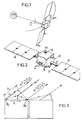
- FIG. 2 shows a possible constitution of a satellite 10 whose attitude with respect to the earth has to be determined.
- This satellite comprises a body 12 and solar panels 14.
- a star sensor 16 On the body is placed a star sensor 16 having a wide angular field.
- This star sensor can be completed by a terrestrial or solar horizon sensor.
- a stellar sensor 16 with a large field.
- Such a sensor has the advantage of allowing detection only on the basis of stars having a low magnitude, less than four for example.
- the catalog of stars to be memorized does not exceed 300 stars, which facilitates management and authorizes image processing on board the satellite.
- the body 12 of the satellite also carries at least three antennas for receiving the signals transmitted by the GPS satellites.
- the antennas 18 are provided, at the four corners of the body of the satellite so as to have maximum precision.
- each attitude measurement by GPS interferometry can be made using a set of three antennas only. By carrying out several measurements, each time with a set of three different antennas, one can increase the accuracy and also carry out doubt surveys.
- each antenna 18 with a mask which limits the angle at the top of the reception cone to a value less than 180 °, for example 140 °.
- the number of satellites in direct view varies, over a period of twelve hours, between three and eight with such a mask.
- Figure 3 shows the principle of attitude measurement by interferometry from the signals supplied by two GPS antennas.
- the phase shift between the signals supplied by the two antennas 18 1 and 18 2 depends on the orientation of the base b (line connecting 18 1 and 18 2 ) with respect to the direction defined by a unit vector s j of the incident wave from a GPS satellite of order j.
- the number of possible measurements is equal to the product of the number of GPS satellites simultaneously visible by the number of antenna bases available.
- these antennas are grouped so that one constitutes a master antenna, forming a common reference, and each of the others a slave antenna.
- ⁇ ij constitutes an error term, due essentially to multiple paths, different for each base and each GPS satellite. This term evolves slowly over time. Consequently, a value calculated by calibration using the stellar sensor can be kept for a blind period which follows.
- each path difference is made up of the scalar product of the base vector of antennas b i and of the unit vector s j of signal direction (satellite vector - GPS satellite observed).
- This scalar product involves the rotation matrix between the satellite reference point and the terrestrial reference point in which the outputs of the GPS receiver are given. It therefore suffices from two antenna bases, therefore from three antennas, and from two GPS satellites to determine the attitude along three axes of the satellite.
- the acquisition procedure guarantees a score better than 10 ° to rule out the problem. Otherwise, the ambiguity can be removed by comparing the results provided by a large number of bases.
- a first source is constituted by the multiple paths such as those shown in FIG. 3. This effect, linked to the use of radio frequencies, is reproducible.
- the attitude of the satellite can be defined by the matrix A of passage from the satellite frame of reference Xs Ys Zs to the orbital frame of reference XYZ.
- the set of measurements for several antenna bases and several GPS satellites provides a system of equations with three unknowns, the number of which is overabundant. For small deflection angles, these equations are linear and allow a solution by the method of least squares. In practice, it is always possible to reduce this situation by an appropriate choice of the reference frame XsYsZs linked to the satellite.
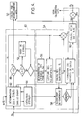
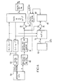
- the necessary measurements can be made using a multiplexer which makes it possible to successively connect each of the antennas to a measurement chain comprising a receiver, a correlator involving the phase and quadrature components of the signal and, for each slave antenna, a differential filter. phase which provides a phase difference.
- the angular velocity r can also be calculated.
- the measurement by GPS interferometry can be carried out at a high rate but the accuracy of the attitude measurement by GPS interferometry alone is limited to a value which may be insufficient. For example, it is around 0.5 ° to 3 ° for a GPS system alone and a satellite of the kind defined above. This limitation is notably due to the existence of multiple paths, differences between cable bias of link and differences between the phase centers of the GPS antennas.
- the last two sources of error can be calibrated once and for all.
- Accuracy can be significantly improved by taking into account the error due to multiple paths by repeated calibrations using the star sensor, which achieves an accuracy of about 0.15 ° on its line of sight and maintain almost equal accuracy by GPS interferometry and calibration.
- the sensor can be of a known matrix type, which therefore need not be described. It receives the angles identifying the pointing ⁇ n obtained during the previous measurement of order n and includes a selection logic 40 intended to choose a group of three stars for each calculation, from among the many stars contained in the field of vision of the sensor. 16 ( Figure 2).
- a first test 48 is carried out on the number of visible stars. If it is less than 2, no measurement is carried out and the hand passes to the system 50 of attitude calculation by GSM interferometry.
- step 52 allows you to select three stars; for example the three stars chosen can be either the three brightest, or the brightest star and those which have the greatest angular difference between them and with the brightest star.
- the computer 54 itself comprises, at the input, a member or a step 56 for choosing the windows of the field of vision to be analyzed for each star selected. It provides, at the output, a half-width of window of angular extent ⁇ u i for each of the stars retained, of position u i .
- the detector comprises a CCD matrix whose photosensitive sites are read in each of the three windows, each extending from u i - ⁇ u i to u i + ⁇ u i , thus providing illumination signals E for all the photosensitive sites. in each window.
- a classical calculation of the barycenter of each spot corresponding to a star provides an estimated value û i , generally different from u i and due to the difference between the input value ⁇ s and the real value for which an estimate is sought. ⁇ ⁇ s.
- the coherence of the measurements can be determined by applying in 58 an algorithm for evaluating a coherence index using as a reference the memorized characteristics of the star observed and making it possible to rule out errors due to the presence of another satellite or from a distant planet in the field of vision.
- the index obtained is compared with a threshold.
- the matrix R is formed of the terms R ii ; which are functions of the magnitude M i of the star measured and the direction measured û i ; we can also give it a value which is a function of ⁇ ', that is to say the scrolling speed.
- the product B. ⁇ u provides the attitude increment ⁇ which is added to the original value ⁇ S and provides an estimate ⁇ ⁇ S which will be used in place of ⁇ for the next measurement and will be used to recalibrate the measurement device by GPS interferometry. In order to obtain sufficient accuracy, a measurement rate of at least 8 Hz is generally required.
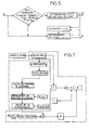
- the algorithm for selecting between measurement by GPS interferometry and measurement using the stellar sensor can be that shown diagrammatically in FIG. 5, assuming an initial coarse measurement already available, for example by a three-axis magnetometer. The measurement is carried out by star sensor, except in cases where it is not possible. The results of the measurement, whatever the mode used, are re-entered at the input.
- block 62 designates all of the means shown in Figure 4 and which provide the angles defining the attitude (which will be designated as a whole by ⁇ e to differentiate them from the angles ⁇ g obtained by GPS interferometry) and the rotation matrix A.
- phase differences ⁇ ij are calculated in 68 for all the bases b i .
- the least squares resolution will provide a and c.
- the attitude matrix is then the product of A by the transition matrix from the local orbital frame to the inertial frame marked inv (Rol.In) and the angles ⁇ x, ⁇ y, ⁇ z are then determined by identification.
- the calculation steps can be those summarized in Figure 8, with the usual mathematical notations.
Landscapes
- Engineering & Computer Science (AREA)
- Remote Sensing (AREA)
- Radar, Positioning & Navigation (AREA)
- Computer Networks & Wireless Communication (AREA)
- Physics & Mathematics (AREA)
- General Physics & Mathematics (AREA)
- Automation & Control Theory (AREA)
- Chemical & Material Sciences (AREA)
- Combustion & Propulsion (AREA)
- Aviation & Aerospace Engineering (AREA)
- Position Fixing By Use Of Radio Waves (AREA)
- Navigation (AREA)
Applications Claiming Priority (2)
| Application Number | Priority Date | Filing Date | Title |
|---|---|---|---|
| FR9514228 | 1995-12-01 | ||
| FR9514228A FR2741955B1 (fr) | 1995-12-01 | 1995-12-01 | Procede et dispositif de mesure d'attitude de satellite |
Publications (2)
| Publication Number | Publication Date |
|---|---|
| EP0777128A1 true EP0777128A1 (de) | 1997-06-04 |
| EP0777128B1 EP0777128B1 (de) | 2001-11-07 |
Family
ID=9485059
Family Applications (1)
| Application Number | Title | Priority Date | Filing Date |
|---|---|---|---|
| EP96402579A Expired - Lifetime EP0777128B1 (de) | 1995-12-01 | 1996-11-28 | Verfahren und Gerät zur Lagemessung eines Satelliten |
Country Status (5)
| Country | Link |
|---|---|
| US (1) | US5831572A (de) |
| EP (1) | EP0777128B1 (de) |
| CA (1) | CA2191550A1 (de) |
| DE (1) | DE69616720D1 (de) |
| FR (1) | FR2741955B1 (de) |
Cited By (4)
| Publication number | Priority date | Publication date | Assignee | Title |
|---|---|---|---|---|
| EP0910001A3 (de) * | 1997-08-12 | 2000-08-23 | Honeywell Inc. | Bestimmung der Lage eines Satelliten |
| EP0908806A3 (de) * | 1997-09-16 | 2000-09-27 | Space Systems/Loral, Inc. | GPS-Lagebestimmung mit Selbstkalibrierung |
| WO2007082929A1 (fr) * | 2006-01-19 | 2007-07-26 | Thales | Dispositif de controle de position(s) relative(s) par analyse de signaux bi-frequences, pour un engin spatial d'un groupe d'engins spatiaux en formation |
| CN104252004A (zh) * | 2014-09-11 | 2014-12-31 | 上海卫星工程研究所 | 利用单天线导航接收机测量自旋卫星姿态的系统及方法 |
Families Citing this family (14)
| Publication number | Priority date | Publication date | Assignee | Title |
|---|---|---|---|---|
| US6594582B1 (en) * | 1999-05-14 | 2003-07-15 | The United States Of America As Represented By The Administrator Of The National Aeronautics And Space Administration | GPS compound eye attitude and navigation sensor and method |
| US6463366B2 (en) | 2000-03-10 | 2002-10-08 | Schafer Corp | Attitude determination and alignment using electro-optical sensors and global navigation satellites |
| US6760664B1 (en) * | 2001-06-25 | 2004-07-06 | The United States Of America As Represented By The Administrator Of The National Aeronautics And Space Administration | Autonomous navigation system based on GPS and magnetometer data |
| US7124001B2 (en) * | 2003-07-11 | 2006-10-17 | The Boeing Company | Relative attitude estimator for multi-payload attitude determination |
| US7310578B2 (en) * | 2004-01-09 | 2007-12-18 | The Boeing Company | Fast access, low memory, pair catalog |
| US7822572B2 (en) * | 2007-07-06 | 2010-10-26 | Beihang University | Method and device for calibration of digital celestial sensor |
| US8130142B2 (en) | 2009-09-21 | 2012-03-06 | Appareo Systems, Llc | GNSS ultra-short baseline heading determination system and method |
| US9074892B2 (en) | 2013-03-15 | 2015-07-07 | Ian Michael Fink | System and method of determining a position of a remote object |
| US20140267696A1 (en) * | 2013-03-18 | 2014-09-18 | National Applied Research Laboratories (Narl) | Glitch-free data fusion method for combining multiple attitude solutions |
| US9813151B2 (en) * | 2014-08-05 | 2017-11-07 | Massachusetts Institute Of Technology | Free-space optical communication module for small satellites |
| CN105891851B (zh) * | 2015-01-23 | 2018-06-08 | 北京空间飞行器总体设计部 | 一种基于导航卫星漏信号进行定位在轨试验验证方法 |
| US11592578B2 (en) * | 2016-12-30 | 2023-02-28 | U-Blox Ag | GNSS receiver protection levels |
| CN112257026A (zh) * | 2020-10-22 | 2021-01-22 | 上海卫星工程研究所 | 基于盲源分离的自旋稳定卫星姿态确定方法及系统 |
| CN112882483B (zh) * | 2021-01-12 | 2022-03-04 | 北京控制工程研究所 | 星敏感器在轨标定方法、装置和存储介质 |
Citations (2)
| Publication number | Priority date | Publication date | Assignee | Title |
|---|---|---|---|---|
| US4405986A (en) * | 1981-04-17 | 1983-09-20 | The United States Of America As Represented By The Secretary Of The Army | GSP/Doppler sensor velocity derived attitude reference system |
| DE3417661A1 (de) * | 1983-05-13 | 1984-11-15 | Mitsubishi Denki K.K., Tokio/Tokyo | System zur regelung der lage eines kuenstlichen satelliten |
Family Cites Families (3)
| Publication number | Priority date | Publication date | Assignee | Title |
|---|---|---|---|---|
| US4617634A (en) * | 1983-06-28 | 1986-10-14 | Mitsubishi Denki Kabushiki Kaisha | Artificial satellite attitude control system |
| US5548293A (en) * | 1993-03-24 | 1996-08-20 | Leland Stanford Junior University | System and method for generating attitude determinations using GPS |
| US5561432A (en) * | 1995-05-12 | 1996-10-01 | Trimble Navigation | Out of plane antenna vector system and method |
-
1995
- 1995-12-01 FR FR9514228A patent/FR2741955B1/fr not_active Expired - Fee Related
-
1996
- 1996-11-28 EP EP96402579A patent/EP0777128B1/de not_active Expired - Lifetime
- 1996-11-28 DE DE69616720T patent/DE69616720D1/de not_active Expired - Lifetime
- 1996-11-28 CA CA002191550A patent/CA2191550A1/fr not_active Abandoned
- 1996-11-29 US US08/758,443 patent/US5831572A/en not_active Expired - Fee Related
Patent Citations (2)
| Publication number | Priority date | Publication date | Assignee | Title |
|---|---|---|---|---|
| US4405986A (en) * | 1981-04-17 | 1983-09-20 | The United States Of America As Represented By The Secretary Of The Army | GSP/Doppler sensor velocity derived attitude reference system |
| DE3417661A1 (de) * | 1983-05-13 | 1984-11-15 | Mitsubishi Denki K.K., Tokio/Tokyo | System zur regelung der lage eines kuenstlichen satelliten |
Non-Patent Citations (3)
| Title |
|---|
| LUCAS R ET AL: "GLOBAL POSITIONING SYSTEM INTEGRATED NAVIGATION AND ATTITUDE DETERMINATION SYSTEM (GINAS)", SIGNAL PROCESSING THEORIES AND APPLICATIONS, BARCELONA, SEPT. 18 - 21, 1990, vol. 3, 18 September 1990 (1990-09-18), TORRES L;MASGRAU E; LAGUNAS M A, pages 1747 - 1750, XP000365903 * |
| STEIN B A ET AL: "SATELLITE ATTITUDE DETERMINATION USING GPS", 500 YEARS AFTER COLUMBUS - NAVIGATION CHALLENGES OF TOMORROW, MONTEREY, CA., MAR. 23 - 27, 1992, 1 January 1992 (1992-01-01), INSTITUTE OF ELECTRICAL AND ELECTRONICS ENGINEERS, pages 544, XP000344349 * |
| UNWIN ET AL: "RESULTS FROM THE POSAT GPS EXPERIMENT", POSITION LOCATION AND NAVIGATION SYMPOSIUM (PLANS), LAS VEGAS, APR. 11 - 15, 1994, 11 April 1994 (1994-04-11), INSTITUTE OF ELECTRICAL AND ELECTRONICS ENGINEERS, pages 598 - 604, XP000489397 * |
Cited By (8)
| Publication number | Priority date | Publication date | Assignee | Title |
|---|---|---|---|---|
| EP0910001A3 (de) * | 1997-08-12 | 2000-08-23 | Honeywell Inc. | Bestimmung der Lage eines Satelliten |
| EP0908806A3 (de) * | 1997-09-16 | 2000-09-27 | Space Systems/Loral, Inc. | GPS-Lagebestimmung mit Selbstkalibrierung |
| WO2007082929A1 (fr) * | 2006-01-19 | 2007-07-26 | Thales | Dispositif de controle de position(s) relative(s) par analyse de signaux bi-frequences, pour un engin spatial d'un groupe d'engins spatiaux en formation |
| EP1813957A1 (de) * | 2006-01-19 | 2007-08-01 | Alcatel Lucent | Vorrichtung zur Regelung der relativen Positionen in einer Gruppe in einer Formation von Raumschiffen durch Analyse von Zweifrequenzsignalen |
| RU2419807C2 (ru) * | 2006-01-19 | 2011-05-27 | Таль | Устройство контроля относительного(ых) положения(й) путем анализа двухчастотных сигналов для космического аппарата группы космических аппаратов при полете строем |
| US8463467B2 (en) | 2006-01-19 | 2013-06-11 | Thales | Device for controlling relative position(s) by analyzing dual-frequency signals, for a spacecraft of a group of spacecraft in formation |
| CN104252004A (zh) * | 2014-09-11 | 2014-12-31 | 上海卫星工程研究所 | 利用单天线导航接收机测量自旋卫星姿态的系统及方法 |
| CN104252004B (zh) * | 2014-09-11 | 2017-01-11 | 上海卫星工程研究所 | 利用单天线导航接收机测量自旋卫星姿态的系统及方法 |
Also Published As
| Publication number | Publication date |
|---|---|
| US5831572A (en) | 1998-11-03 |
| DE69616720D1 (de) | 2001-12-13 |
| CA2191550A1 (fr) | 1997-06-02 |
| EP0777128B1 (de) | 2001-11-07 |
| FR2741955B1 (fr) | 1998-02-06 |
| FR2741955A1 (fr) | 1997-06-06 |
Similar Documents
| Publication | Publication Date | Title |
|---|---|---|
| EP0777128B1 (de) | Verfahren und Gerät zur Lagemessung eines Satelliten | |
| EP3623758B1 (de) | Standortbestimmungssystem und entsprechendes standortbestimmungsverfahren | |
| EP3658921A1 (de) | Verfahren zur kalibrierung eines magnetometers | |
| EP2718670B1 (de) | Vereinfachtes verfahren zur schätzung der ausrichtung eines objekts und lagesensor zur durchführung dieses verfahrens | |
| BE1023739B1 (fr) | Observatoire magnétique autonome et auto-calibré | |
| FR2826447A1 (fr) | Procede et dispositif de navigation inertielle hybride | |
| EP0502771B1 (de) | Verfahren und System zum Abgleich der Einrichtungen an Bord eines Fahrzeugs unter Verwendung von Mitteln zur Messung des irdischen Schwere- und Magnetfelds | |
| WO2010072917A1 (fr) | Procede de determination d'un cap en direction du nord geographique au moyen d'une centrale inertielle | |
| EP2500750B1 (de) | Verfahren und Vorrichtung zur Eichung eines Empfängers | |
| EP2694375A1 (de) | Vorrichtung und verfahren zur bestimmung der lage eines satelliten und satellit mit solch einer vorrichtung | |
| Socas-Navarro et al. | Characterization of telescope polarization properties across the visible and near-infrared spectrum: Case study: the Dunn Solar Telescope | |
| EP2105380B1 (de) | Methode zur Abschätzung der Fluglage eines Sternensensors | |
| EP2410293B1 (de) | Harmonisierungsverfahren und -system eines Referenzsystems eines Winkelpositionierers in Bezug auf ein Erdbezugssystem | |
| EP2476015A1 (de) | Verfahren zur bestimmung der navigationsgeschwindigkeit eines trägers und hybridisierungsvorrichtung | |
| EP3385677A1 (de) | System und verfahren zur analyse und überwachung der störenden bewegungen eines trägheitsnavigationssystems während einer statischen ausrichtungsphase | |
| EP0502770A1 (de) | Verfahren und System zum Abgleich der Einrichtungen an Bord eines Fahrzeugs, unter Verwendung von Mitteln zur Messung des irdischen Schwerefelds | |
| WO2024089353A2 (fr) | Detection et correction de derive d'un dispositif de navigation par visee stellaire | |
| FR3026837A1 (fr) | Dispositif et procede de positionnement d'un capteur stellaire sur la structure d'un satellite | |
| EP4471509B1 (de) | Verfahren zur validierung einer detektion des durchtritts der karmanlinie durch ein tragbares gerät, insbesondere eine uhr | |
| FR3003961A1 (fr) | Procede de formation de faisceau signaux d'un recepteur de signaux d'un systeme de navigation par satellites pour ameliorer la resistance au brouillage. | |
| FR2701762A1 (fr) | Dispositif de restitution d'orbite de corps célestes, notamment de satellites artificiels, par écartométrie. | |
| EP3374736A1 (de) | Verfahren zum entwurf eines navigationspfades und verfahren zur ausrichtung eines sichtungselements von diesem navigationspfad | |
| FR3148643A1 (fr) | Procédé de détermination des invariances temporelles du degré de polarisation linéaire dans le ciel | |
| FR3144274A1 (fr) | Dispositif et procédé de navigation utilisant des données pré-intégrées de façon asynchrone dans une UMI distante | |
| EP0368745A1 (de) | Verfahren, um ein rotierendes Bild auszurichten und Gerät zur Ausführung dieses Verfahrens |
Legal Events
| Date | Code | Title | Description |
|---|---|---|---|
| PUAI | Public reference made under article 153(3) epc to a published international application that has entered the european phase |
Free format text: ORIGINAL CODE: 0009012 |
|
| AK | Designated contracting states |
Kind code of ref document: A1 Designated state(s): BE DE ES GB IT SE |
|
| 17P | Request for examination filed |
Effective date: 19970816 |
|
| 17Q | First examination report despatched |
Effective date: 20000331 |
|
| RAP1 | Party data changed (applicant data changed or rights of an application transferred) |
Owner name: ASTRIUM SAS |
|
| GRAG | Despatch of communication of intention to grant |
Free format text: ORIGINAL CODE: EPIDOS AGRA |
|
| GRAG | Despatch of communication of intention to grant |
Free format text: ORIGINAL CODE: EPIDOS AGRA |
|
| GRAH | Despatch of communication of intention to grant a patent |
Free format text: ORIGINAL CODE: EPIDOS IGRA |
|
| GRAH | Despatch of communication of intention to grant a patent |
Free format text: ORIGINAL CODE: EPIDOS IGRA |
|
| GRAA | (expected) grant |
Free format text: ORIGINAL CODE: 0009210 |
|
| AK | Designated contracting states |
Kind code of ref document: B1 Designated state(s): BE DE ES GB IT SE |
|
| PG25 | Lapsed in a contracting state [announced via postgrant information from national office to epo] |
Ref country code: IT Free format text: LAPSE BECAUSE OF FAILURE TO SUBMIT A TRANSLATION OF THE DESCRIPTION OR TO PAY THE FEE WITHIN THE PRE;WARNING: LAPSES OF ITALIAN PATENTS WITH EFFECTIVE DATE BEFORE 2007 MAY HAVE OCCURRED AT ANY TIME BEFORE 2007. THE CORRECT EFFECTIVE DATE MAY BE DIFFERENT FROM THE ONE RECORDED.SCRIBED TIME-LIMIT Effective date: 20011107 Ref country code: GB Free format text: LAPSE BECAUSE OF FAILURE TO SUBMIT A TRANSLATION OF THE DESCRIPTION OR TO PAY THE FEE WITHIN THE PRESCRIBED TIME-LIMIT Effective date: 20011107 |
|
| PG25 | Lapsed in a contracting state [announced via postgrant information from national office to epo] |
Ref country code: BE Free format text: LAPSE BECAUSE OF NON-PAYMENT OF DUE FEES Effective date: 20011130 |
|
| REF | Corresponds to: |
Ref document number: 69616720 Country of ref document: DE Date of ref document: 20011213 |
|
| REG | Reference to a national code |
Ref country code: GB Ref legal event code: IF02 |
|
| PG25 | Lapsed in a contracting state [announced via postgrant information from national office to epo] |
Ref country code: SE Free format text: LAPSE BECAUSE OF FAILURE TO SUBMIT A TRANSLATION OF THE DESCRIPTION OR TO PAY THE FEE WITHIN THE PRESCRIBED TIME-LIMIT Effective date: 20020207 |
|
| PG25 | Lapsed in a contracting state [announced via postgrant information from national office to epo] |
Ref country code: DE Free format text: LAPSE BECAUSE OF FAILURE TO SUBMIT A TRANSLATION OF THE DESCRIPTION OR TO PAY THE FEE WITHIN THE PRESCRIBED TIME-LIMIT Effective date: 20020208 |
|
| GBV | Gb: ep patent (uk) treated as always having been void in accordance with gb section 77(7)/1977 [no translation filed] |
Effective date: 20011107 |
|
| PG25 | Lapsed in a contracting state [announced via postgrant information from national office to epo] |
Ref country code: ES Free format text: LAPSE BECAUSE OF FAILURE TO SUBMIT A TRANSLATION OF THE DESCRIPTION OR TO PAY THE FEE WITHIN THE PRESCRIBED TIME-LIMIT Effective date: 20020530 |
|
| BERE | Be: lapsed |
Owner name: ASTRIUM SAS Effective date: 20011130 |
|
| PLBE | No opposition filed within time limit |
Free format text: ORIGINAL CODE: 0009261 |
|
| STAA | Information on the status of an ep patent application or granted ep patent |
Free format text: STATUS: NO OPPOSITION FILED WITHIN TIME LIMIT |
|
| 26N | No opposition filed |