EP0777170A1 - Steuereinrichtung für ein elektrisches Gerät - Google Patents
Steuereinrichtung für ein elektrisches Gerät Download PDFInfo
- Publication number
- EP0777170A1 EP0777170A1 EP96402333A EP96402333A EP0777170A1 EP 0777170 A1 EP0777170 A1 EP 0777170A1 EP 96402333 A EP96402333 A EP 96402333A EP 96402333 A EP96402333 A EP 96402333A EP 0777170 A1 EP0777170 A1 EP 0777170A1
- Authority
- EP
- European Patent Office
- Prior art keywords
- circuit
- rules
- signal
- membership functions
- account
- Prior art date
- Legal status (The legal status is an assumption and is not a legal conclusion. Google has not performed a legal analysis and makes no representation as to the accuracy of the status listed.)
- Granted
Links
- 230000006870 function Effects 0.000 claims abstract description 96
- 238000005259 measurement Methods 0.000 claims abstract description 14
- 230000015654 memory Effects 0.000 claims abstract description 12
- 230000008859 change Effects 0.000 claims description 9
- 230000005540 biological transmission Effects 0.000 claims description 2
- 230000009471 action Effects 0.000 description 14
- 230000001276 controlling effect Effects 0.000 description 8
- 238000000034 method Methods 0.000 description 8
- 238000013475 authorization Methods 0.000 description 4
- 238000011156 evaluation Methods 0.000 description 4
- 238000009529 body temperature measurement Methods 0.000 description 3
- 238000001514 detection method Methods 0.000 description 3
- 238000011161 development Methods 0.000 description 3
- 230000018109 developmental process Effects 0.000 description 3
- 238000012545 processing Methods 0.000 description 3
- 238000012546 transfer Methods 0.000 description 3
- 230000001960 triggered effect Effects 0.000 description 3
- 230000003247 decreasing effect Effects 0.000 description 2
- 238000010438 heat treatment Methods 0.000 description 2
- 238000009434 installation Methods 0.000 description 2
- 230000002829 reductive effect Effects 0.000 description 2
- 210000001015 abdomen Anatomy 0.000 description 1
- 238000009825 accumulation Methods 0.000 description 1
- 230000032683 aging Effects 0.000 description 1
- 238000013459 approach Methods 0.000 description 1
- 238000006243 chemical reaction Methods 0.000 description 1
- 238000010276 construction Methods 0.000 description 1
- 230000036461 convulsion Effects 0.000 description 1
- 230000008878 coupling Effects 0.000 description 1
- 238000010168 coupling process Methods 0.000 description 1
- 238000005859 coupling reaction Methods 0.000 description 1
- 230000001627 detrimental effect Effects 0.000 description 1
- 239000006185 dispersion Substances 0.000 description 1
- 230000005611 electricity Effects 0.000 description 1
- 230000005670 electromagnetic radiation Effects 0.000 description 1
- 235000021183 entrée Nutrition 0.000 description 1
- WABPQHHGFIMREM-UHFFFAOYSA-N lead(0) Chemical compound [Pb] WABPQHHGFIMREM-UHFFFAOYSA-N 0.000 description 1
- 230000000670 limiting effect Effects 0.000 description 1
- 238000004377 microelectronic Methods 0.000 description 1
- 238000012986 modification Methods 0.000 description 1
- 230000004048 modification Effects 0.000 description 1
- 238000010606 normalization Methods 0.000 description 1
- 210000000056 organ Anatomy 0.000 description 1
- 230000008520 organization Effects 0.000 description 1
- 244000045947 parasite Species 0.000 description 1
- 230000036961 partial effect Effects 0.000 description 1
- 230000002093 peripheral effect Effects 0.000 description 1
- 230000008569 process Effects 0.000 description 1
- 238000011002 quantification Methods 0.000 description 1
- 230000001105 regulatory effect Effects 0.000 description 1
- 230000000717 retained effect Effects 0.000 description 1
- 238000004088 simulation Methods 0.000 description 1
- 230000002123 temporal effect Effects 0.000 description 1
- 230000009466 transformation Effects 0.000 description 1
- 238000000844 transformation Methods 0.000 description 1
- 238000010200 validation analysis Methods 0.000 description 1
Images

Classifications
-
- G—PHYSICS
- G05—CONTROLLING; REGULATING
- G05D—SYSTEMS FOR CONTROLLING OR REGULATING NON-ELECTRIC VARIABLES
- G05D23/00—Control of temperature
- G05D23/19—Control of temperature characterised by the use of electric means
- G05D23/1917—Control of temperature characterised by the use of electric means using digital means
-
- G—PHYSICS
- G05—CONTROLLING; REGULATING
- G05B—CONTROL OR REGULATING SYSTEMS IN GENERAL; FUNCTIONAL ELEMENTS OF SUCH SYSTEMS; MONITORING OR TESTING ARRANGEMENTS FOR SUCH SYSTEMS OR ELEMENTS
- G05B13/00—Adaptive control systems, i.e. systems automatically adjusting themselves to have a performance which is optimum according to some preassigned criterion
- G05B13/02—Adaptive control systems, i.e. systems automatically adjusting themselves to have a performance which is optimum according to some preassigned criterion electric
- G05B13/0265—Adaptive control systems, i.e. systems automatically adjusting themselves to have a performance which is optimum according to some preassigned criterion electric the criterion being a learning criterion
- G05B13/0275—Adaptive control systems, i.e. systems automatically adjusting themselves to have a performance which is optimum according to some preassigned criterion electric the criterion being a learning criterion using fuzzy logic only
-
- Y—GENERAL TAGGING OF NEW TECHNOLOGICAL DEVELOPMENTS; GENERAL TAGGING OF CROSS-SECTIONAL TECHNOLOGIES SPANNING OVER SEVERAL SECTIONS OF THE IPC; TECHNICAL SUBJECTS COVERED BY FORMER USPC CROSS-REFERENCE ART COLLECTIONS [XRACs] AND DIGESTS
- Y10—TECHNICAL SUBJECTS COVERED BY FORMER USPC
- Y10S—TECHNICAL SUBJECTS COVERED BY FORMER USPC CROSS-REFERENCE ART COLLECTIONS [XRACs] AND DIGESTS
- Y10S706/00—Data processing: artificial intelligence
- Y10S706/90—Fuzzy logic
Definitions
- the present invention relates to a device for controlling any electrical appliance. However, it relates more particularly to regulation control devices, or regulation. It also relates to electrically powered devices which are also controlled by a control circuit for which an additional function is added to the control circuit.
- the device is an electric heater. But this device could nevertheless be any other device: a household or industrial appliance, and having the particularity of being electrical, supplied by an electrical supply (for example the mains), and moreover having a control circuit.
- radiators In the field of controlling electrical devices, in particular radiators, it is known to provide control functions with electronic circuits, in particular electronic circuits comprising processors or microprocessors associated with program memories and peripheral control circuits .
- electronic circuits in particular electronic circuits comprising processors or microprocessors associated with program memories and peripheral control circuits .
- the so-called Motorola UAA2016 circuit is known, which makes it possible to regulate the thermal power dissipated by a radiator according to a measurement of the ambient temperature and of a set temperature displayed by a user on a button. control.
- the temperature sensor is a CTN type resistor.
- the aforementioned circuit includes the possibility of taking account of another resistor of the same type, placed in another location near the radiator (generally at the bottom of the radiator), so as to compensate for drifts or non-linearities.
- This way of doing things has the disadvantage that the device produced is expensive because the resistors of the CTN type are themselves expensive to have the most linear components possible. It also has the disadvantage of requiring long and laborious studies for the development of the transfer of regulation function controlled by this circuit.
- this transfer function largely depends on the geometry of the radiator and in particular on the position of the CTN detection resistors at the various locations of the radiator. This process also presents an inevitable problem: it does not take into account the size of the room and the place in the room where the radiator is placed.
- the circuit concerned when it performs its regulating function, delivers a signal which is transmitted to a circuit for switching on the thermal resistances of the radiator. This conduction circuit is ultimately the circuit for using the regulation signal, the control signal.
- a stop mode in which the installation is definitively stopped and whatever the orders applied to each of the radiators they cannot start producing heat.
- the circuit mentioned above is not capable of managing this so-called piloting information. Also, it has become customary to add to this regulation circuit an additional microcontroller, the signal of which is ultimately a signal for validation or modification of the operation of the aforementioned circuit.
- This additional microcontroller receives by a wire called pilot wire the information coming from the general control of the house by which the user has imposed a general mode of operation.
- the pilot wire can be a wire or a bus, the main thing being that it conveys the operating mode information.
- the processing of the information of the pilot wire by the microcontroller takes priority over the regulation exerted by the aforementioned circuit.
- the time constant of regulation is long compared to the duration of the reception of the remote control information of the pilot wire which on the one hand is short and which on the other hand is random.
- the information in the pilot wire can have a duration of 20 milliseconds.
- the microcontroller system will handle an interrupt.
- this device continues to remain expensive due to the presence of the two resistors of the CTN type.
- a new standard in particular the European standard ICE 555-1 / 2/3, requires limiting the value of the reactive impedances generated by untimely consumption of the mains electric current. Indeed, when a device is powered up, it is possible that the phase of the sector corresponds to a voltage or current belly. Under these conditions the current draw is very strong and causes, due to the various electrical consumptions, a distortion of the signal existing on the network. This distortion leads to the presence of harmonics, in particular harmonics 3 (at 150 Herz) which are detrimental to the operation of generators producing electricity or which produce electromagnetic radiation and parasites disturbing the proper functioning of neighboring electrical devices. To avoid this drawback, it is agreed that the electrical devices should be triggered in a preferred manner at the moment when the mains electric current goes through zero.
- the object of the invention is to remedy these problems.
- a circuit of fuzzy logic type We will show that with such a fuzzy logic circuit thus developed, we will be able to get rid of the problem associated with drifts or non-linearities of the sensors. We can then be satisfied with a single temperature sensor. The drift of the sensor will be managed by the fuzzy logic program implemented by the circuit.
- remote control information for example of pilot wire type or of synchronization on the zero crossing of the voltage
- management of remote control information is taken into account in the invention by quite simply adding a set of membership functions linked to the presence of the new information to be processed: the information of pilot wire or of passage through zero.
- the lead wire or zero crossing information will be treated as one of the variables managed elsewhere by the fuzzy logic circuit.
- the fuzzy logic circuit comprising a rule set of the type "if the result of a sensor is in a given state then the result of the command must be in a given state" will, in the invention, be supplemented by a rule of next type "if the sensor is in a given state, and if the pilot wire (or zero crossing) information is in a given state, then the command must be in a given state".
- This general approach makes it possible to take into account quite naturally as many external constraints as desired. Of course it is possible to combine together the presence of the temperature sensor, the presence of the pilot wire information, and the presence of the sensor for detecting the zero current of the supply current. We will show later that the choice of this solution makes it possible to take into account in a particularly simple way the most varied situations, for the most diverse devices.
- Figure 1 shows a device for controlling the operation of an apparatus.
- the device is a radiator 1.
- the device mainly comprises a measurement sensor, here to simplify a temperature sensor 2 ⁇ , for example a CTN type resistor plated at the top of the radiator. Its signal takes into account the temperature at the top of the radiator and the ambient temperature at the top of this radiator.
- the control device further comprises a circuit for controlling this operation.
- the control circuit comprises a microprocessor 3, essentially provided with an arithmetic and logic processing unit, as well as other associated members which will be seen below.
- the control device also includes a mode change control input 4 for receiving a mode change signal.
- the mode change signal is delivered by a control unit 5 electrically connected 6 or electromagnetically 7 to a circuit 8 for taking into account the mode change order.
- the box 5 includes a set of buttons such as 9 for delivering the signal for changing the mode appropriate to the chosen mode.
- the signal from the box 5 ended up on the microcontroller. The output of the microcontroller controlled the operation of the above-mentioned regulation circuit.
- control device further comprises a program memory 10 which contains a set 11 of membership functions, a set 12 of decision rules, and a fuzzy logic program 13 corresponding to the fuzzy model of the system.
- the microprocessor 3 of the control circuit is a fuzzy logic processor which is used to develop a decision signal.
- This decision signal is a function of the signal emitted by the sensor 2, and is a function, in application of the fuzzy logic program, of the set 11 of the membership functions and of the set 12 of the decision rules.
- the membership functions include membership functions linked to the presence of the pilot thread information and the decision rules take into account the value of these membership functions to develop the result: the decision .
- circuits are connected to each other by a bus 14 which, to simplify the explanation, will be used to convey both the addresses, the data, and the commands.
- the bus 14 is also connected with a circuit 15 for commissioning the device 1.
- the circuit 15 will simply include a set of triacs whose switching will be organized according to the desired power to be dissipated with the radiator 1.
- the circuit 15 could be a circuit for converting the decision information into a series of pulses modulated in duration (PWM type).
- PWM type pulses modulated in duration
- the circuit 15 is connected to the electrical sector 16, receives on an input 17 the decision signal, and delivers at the output an electrical power necessary for the chosen operation of the device 1.
- the device of the invention also includes a circuit 19 for detecting the passage of the supply current through zero.
- the circuit 19 is a circuit of known type. It is represented here by a symbolism showing the zero crossing of the alternating voltage V as a function of time t.
- this circuit will include a rectifier circuit, or preferably an analog-digital converter capable of transform the AC sector signal into digital information: positive or negative depending on the alternation.
- the circuit 19 will also include a comparator to compare the absolute value of the signal delivered by the analog-digital converter and to deliver a signal corresponding to the difference between this absolute value and this reference value. This difference is eliminated when it is positive (corresponding to the periods when the absolute value of the voltage is greater than the reference).
- the signal delivered by the circuit 19 is routed under the same conditions by the bus 14 and corresponds, in the set 11 of membership functions to membership functions of the type taking into account the voltage zero and in the set 12 of the rules with a condition relating to the value of these membership functions.
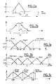
- FIG. 2a shows for a total dynamic range 20 of a value between two limits, for example here between 0 and 1, a reduced value range 21.
- the dynamic range 20 from 0 to 1 is in fact a normalized dynamic.
- the ratio of the measured value to the total value of the measurement dynamics will be taken for each measurement sensor.
- Standardization is not a necessity but in many cases it can be more practical for implementing the method of the invention. Indeed, in this case the forms of the membership functions can themselves be standardized.
- a membership function is a curve revealing the relationship between an abscissa: a measurement value, and an ordinate: a membership coefficient. This curve is qualified by a phenomenon which it represents: for example a phenomenon of heat called "hot” or "very hot". For each measured value, we can refer to the curve to determine a membership coefficient. The membership coefficient is then a quantification of a declaration that an object for which the value has been measured is deemed to belong to the phenomenon, to a range. For example, we will say that for an object producing the value 22, the membership coefficient to the membership function linked to the range 21 has a value 23.
- the membership functions have isosceles, scalene or other forms, and the coefficients have zero values outside the range, and a maximum value for a given value.
- the result membership functions have an average value or a barycenter with a weighting coefficient linked to the area and the position of the membership function.
- FIG. 2a shows the forms of the membership functions used for the measurement sensors, as well as preferably for the management of the setpoint, the management of the information of the pilot wire, or the management of the passage through zero of the voltage.
- FIG. 2b shows another form of membership function in the form of a truncated gaussian included in a range 24 with a mean value 25 and a standard deviation 26.
- the transfer function to be simulated is strongly nonlinear, for the result membership functions we will prefer to use truncated Gaussian forms. In other cases, we will prefer triangular shapes. Depending on their form, they allow a better appreciation of the decision to be applied, taking into account the measures performed.
- Figures 3a to 3c show, a partial implementation of the device of the invention.
- Figure 3a shows membership functions of the temperature measurement. It shows in particular a first so-called cold function, a second so-called hot function and a third so-called very hot function.
- the first so-called cold function indicates, with a right trapezoid shape, that below 7 ° we will say that it is cold with certainty, the coefficient being 1, while between 7 ° and 10 °, we will say that it is cold with a certainty decreasing proportionally with the evolution of the temperature between 7 ° and 10 °.
- the so-called hot temperature membership function indicates that it will be considered warm, with a coefficient ranging from 0 to 1, depending on whether the measured temperature changes from 7 ° to 15 °, then with a decreasing coefficient of 1 to 0 depending on whether the temperature goes from 15 ° to 23 °.
- the third membership function indicates that it will be considered to be very hot with a coefficient of 0 to 1 respectively, then always 1 depending on whether the temperature changes from 19 ° to 25 ° then from 25 ° to 30 °.
- FIG. 3b relates to the taking into account of the set value displayed by a user on the radiator which is in front of him or on the device which he seeks to control.
- This instruction can be taken into account as it is. Or it can be taken into account by difference compared to the value measured by the sensor.
- This value can then belong to membership functions called normal, false-, false +, very false- or very false +.
- the shapes are those shown in FIG. 3b the maximum tolerable difference being of the order of 5 °.
- Figure 3c shows decision membership functions indicating that the action to be exercised can be weak, strong or very strong. As indicated above, the membership functions of decisions, therefore actions, have truncated Gaussian forms. While FIGS. 3a and 3b have non-normalized values on the abscissa, in degrees, FIG. 3c comprises normalized values between 0 and 1.
- FIGS. 4a to 4c we will now take into account in an additional way the information given by the pilot wire (FIG. 4a, 4b), or by the detection of the passage through zero of the electrical supply voltage.
- Figure 4c shows on the abscissa, on a change in temperature t °, ranges corresponding to operating modes of the device. It also shows a pattern of the pilot wire signal corresponding to each mode.
- Figure 4b shows these elements by quantifying the pilot wire signal between 0 and 1. It will be determined that for a first range of this signal, where the value of the variable is between 0 and 0.25, the operating mode will be a stop mode.
- the operating mode is a so-called frost-free mode corresponding to maintaining the temperature of the room and generally of the building above 7 °.
- the mode will be the economic mode in which the temperature of the building must be between 10 ° and 15 °.
- the fourth mode for variable values between 0.75 and 1 the building must be maintained at a temperature between 19 ° and 20 ° (or at another temperature displayed by the user).
- Mode change orders are normally normalized.
- Switching to stop mode is normally imposed by sending a positive pulse to the pilot wire 6.
- the mode change to frost protection is obtained by sending a negative pulse 28 to the same wire 6.
- switching to economic mode is obtained by sending a positive pulse 29 followed by a negative pulse 30.
- Switching to comfort mode can be either automatic (resulting from a time delay) or carried out by sending on the wire pilot 6 of a negative pulse 31 followed by a negative pulse 32.
- the circuit 8 will include a decoder to decode the appearance of these pulses. This decoder circuit will be able in one example to produce a voltage v, applied to a resistance divider bridge (shown here diagrammatically) 33 34.
- the midpoint of the resistance divider bridge can then deliver a voltage signal which, once normalized, will be between 0 and 1, and preferably with average values equal to 0.125 0.375 0.625 0.875.
- the membership functions overlap. For example, we have shown in dashes that the frost-free membership function overlaps the economic membership function in such a way that the sum of the membership coefficients of these two functions membership is always equal to 1.
- the so-called pilot wire information is information delivered by the circuit 8 being between 0 and 1 depending on the value of the signal emanating from the box 5.
- FIG. 4c represents a single membership function corresponding to the taking into account of the zero crossing of the power supply signal of the device.
- the membership coefficient is only significant (different from zero) if the power supply signal is for example between -15 volts and +15 volts, (for a voltage measurement) . If the current is measured, a value for the intensity of the useful electrical signal will be determined.
- the operation of the device of the invention is as follows. In running order, the setpoint signal, the signal delivered by the sensor 2, the signal delivered by the circuit 8, and that delivered by the circuit 19 are transmitted to the microprocessor 3. This transmission is accompanied by all the usual transformations: analog-digital conversion, normalization if the need arises, as well as multiplexing if bus 14 is common: each sensor sending its data in turn. Each of these data is then used in the membership functions which concern it. In practice, each datum is equivalent to an abscissa 33 giving rise to the evaluation of membership coefficients, here respectively 34 and 35, of the membership functions respectively 36 and 37 for which these coefficients are non-zero. For example the coefficient 34 will be worth 0.66 while the coefficient 35 will be worth 0.33. This evaluation is simply a reading of a table in which the address is the value of the measurement (the data transmitted to the microprocessor 3), and in which the value read is the corresponding membership coefficient.
- the coefficients 0.33, 0.66 etc. being also possibly calculated by the arithmetic and logic unit 38 of the microprocessor 3, we will pass to the evaluation of the corresponding control signal which must be applied by the circuit 15 to the device 1.
- This evaluation passes by taking into account account for a number of rules contained in set 12 of the rules.
- the rules are of the type, for simplicity, if the temperature ⁇ measured is hot (see Figure 3a), and if the temperature difference is false - (see Figure 3b), then the action to be taken (decision D) must to be a weak action. Indeed, in this case, it is not necessary to heat very strongly since the temperature difference is small.
- Another rule can be, if the measured temperature belongs to the cold membership function, and if the temperature difference from the setpoint indicates a very false membership function - then the action to be generated will be either a strong action or possibly even a very strong action. And so on.
- the temperature measurement and, indirectly, the target quantity since the difference between the target value and the measured temperature
- M membership functions for the temperature measurement and N membership functions for the measurement of the deviation there will be a total of M x N possible situations. In other words, the system will lead to establishing M x N rules. In this case, there are fifteen rules since M is 3 and N is 5.
- the sets of possible rules are indicated comfort, economic, frost-free, or stop depending on the goal.
- the membership function of FIG. 4c is a membership function called authorization, because, around zero, the device is authorized to be triggered when when the voltage is outside this range close to zero, the device will not be allowed to start.
- the set of rules then includes, in the sixty rules mentioned, an additional condition: does the measurement variable for the zero crossing of the supply voltage also belong to the authorization membership function or not. It will then suffice to add a sixty-first rule indicating that when the measurement variable of the zero crossing of the supply voltage does not belong to the function membership authorization, the decision will be to do nothing.
- the membership functions or rules can be programmed manually in memory 10 or be the result of a simulation made on a set of type 1 devices. They can also be the result of a processing carried out by software called WARP by SGS THOMSON MICROELECTRONICS.
- the implementation of fuzzy logic can then be done, according to several methods, in particular according to a method called the product or according to a method called the minimum. We will describe the latter, knowing that other methods are known whose purpose is to allow the development of a decision signal.
- the minimum method consists in taking into account only the rules for which the coefficients of belonging to the functions designated in the rule are non-zero. For example, Figure 3a, if the measured temperature is 9.5 ° the coefficient of belonging of the phenomenon to the cold membership function will be 0.25. It will be 0.55 at the hot membership function. If, furthermore, the temperature difference is a difference of 4 °, negative, such that this difference belongs to the very false membership function - with the coefficient 0.75 and to the false membership function - with the coefficient 0.20; and if, moreover, to simplify, the pilot thread information belongs to the economic membership function with the coefficient 1 and the zero crossing function belongs to the authorization membership function with the coefficient 1, there will be four rules that will be involved.
- FIG. 1 also shows, in dashed lines, a circuit 39 interposed on the bus 14 to allow the connection between the device and the microprocessor 3.
- This circuit 39 is preferably a current coupling cell carrier capable of receiving, by carrier current, the signal delivered by the CTN 2 thermistor, possibly by another compensating thermistor 40 (which it is anyway possible to also install in the device of the invention), the signal detection of zero crossing produced by the circuit 19 and on the other hand transmitting in the other direction the decision signals D to be applied to the input 17 of the circuit 15.
- the cell 39 can also be managed autonomously or be managed by a control unit 41 of the microprocessor 3 which also controls all the other organs of its environment.
- the signal delivered by this circuit is also used to put the microprocessor 3 to sleep outside periods when this signal is close to zero.
- Putting this microprocessor 3 to sleep is not a problem because, when it wakes up, the only thing it has to do is find the membership functions of game 11 on the membership functions of the game 11. values of the corresponding coefficients. In practice, this involves reading tables, comprising as many tables as there are ranges of membership functions for the different variables. In the example mentioned so far there are a total of ten tables.
- the memory 10 is a memory of 1 kilobyte.
- the microprocessor 3 must perform ten readings and with the results of these ten readings, it must apply them to sixty-one rules.
- the minimum method described leads to an accumulation over a limited number of rules, four or five in general, and to make a division (which one can possibly do without).
- These operations can be carried out by the microprocessor 3 very quickly. For example for a microprocessor clocked at 11 MHz, this result can be acquired in less than a hundred cycle times, ie in practice in less than 10 microseconds. In practice, we will let the microprocessor 3 perform these operations for about 100 microseconds and we will cut it for the rest of the 20 milliseconds which correspond to the alternation of the electrical supply signal (at 50 Hz). As a result, the consumption of this electronic control will be reduced by a ratio of 100/20,000: by 200 times compared to the situation which would prevail if it were in operation all the time.
- the management mode of the zero crossing of the supply voltage is particularly advantageous in a mode of use known as jerks, "burst" in Anglo-Saxon literature, in which the control of the device, once triggered , will last for a number of periods.
- the burst standard even provides that the number of periods will be that which corresponds to the use of 41 seconds.
- the circuit 15 is capable, receiving a decision on its input 17, of controlling the burst mode accordingly. In this case, the microprocessor 3 can go to sleep for the duration of these 41 seconds.
Landscapes
- Engineering & Computer Science (AREA)
- Physics & Mathematics (AREA)
- Artificial Intelligence (AREA)
- General Physics & Mathematics (AREA)
- Automation & Control Theory (AREA)
- Software Systems (AREA)
- Mathematical Physics (AREA)
- Fuzzy Systems (AREA)
- Health & Medical Sciences (AREA)
- Computer Vision & Pattern Recognition (AREA)
- Evolutionary Computation (AREA)
- Medical Informatics (AREA)
- Feedback Control In General (AREA)
Applications Claiming Priority (2)
| Application Number | Priority Date | Filing Date | Title |
|---|---|---|---|
| FR9514185A FR2741970B1 (fr) | 1995-11-30 | 1995-11-30 | Dispositif de commande d'un appareil electrique |
| FR9514185 | 1995-11-30 |
Publications (2)
| Publication Number | Publication Date |
|---|---|
| EP0777170A1 true EP0777170A1 (de) | 1997-06-04 |
| EP0777170B1 EP0777170B1 (de) | 1998-06-03 |
Family
ID=9485031
Family Applications (1)
| Application Number | Title | Priority Date | Filing Date |
|---|---|---|---|
| EP96402333A Expired - Lifetime EP0777170B1 (de) | 1995-11-30 | 1996-10-31 | Steuereinrichtung für ein elektrisches Gerät |
Country Status (4)
| Country | Link |
|---|---|
| US (1) | US5998769A (de) |
| EP (1) | EP0777170B1 (de) |
| DE (1) | DE69600333T2 (de) |
| FR (1) | FR2741970B1 (de) |
Families Citing this family (8)
| Publication number | Priority date | Publication date | Assignee | Title |
|---|---|---|---|---|
| US6922419B1 (en) * | 1996-04-10 | 2005-07-26 | Spectra Physics Lasers, Inc. | Long pulse vanadate laser |
| DE19849075A1 (de) * | 1998-10-24 | 2000-04-27 | Ego Elektro Geraetebau Gmbh | Steuerung für ein Elektrogerät |
| US6374197B1 (en) * | 1999-05-10 | 2002-04-16 | The United States Of America As Represented By The Secretary Of The Navy | Fuzzy logic based model assessment system and method for contact tracking |
| US6648981B2 (en) * | 2001-08-15 | 2003-11-18 | General Electric Company | Methods and systems for dishwasher model selection |
| DE20204570U1 (de) * | 2002-03-21 | 2003-08-07 | Dolmar Gmbh | Handgeführte Arbeitsmaschine mit einer automatisch geregelten Beheizung der Handgriffe |
| US7923306B2 (en) * | 2004-06-18 | 2011-04-12 | Electro Scientific Industries, Inc. | Semiconductor structure processing using multiple laser beam spots |
| WO2017188909A1 (en) * | 2016-04-28 | 2017-11-02 | Gokmen Sabri Haluk | Fuzzy logic algorithm based oven temperature control system |
| CN109827230B (zh) * | 2019-01-09 | 2021-03-12 | 华北电力大学 | 一种供热机组储热罐辅助供热的控制方法 |
Citations (5)
| Publication number | Priority date | Publication date | Assignee | Title |
|---|---|---|---|---|
| US5148977A (en) * | 1990-06-21 | 1992-09-22 | Hitachi, Ltd. | Control system for air-conductioner |
| US5287154A (en) * | 1990-09-12 | 1994-02-15 | Brother Kogyo Kabushiki Kaisha | Thermal toner image fixing device which uses fuzzy logic |
| US5311268A (en) * | 1992-05-21 | 1994-05-10 | Canon Kabushiki Kaisha | Fixing device using fuzzy inference |
| EP0633515A1 (de) * | 1993-07-06 | 1995-01-11 | Ford Motor Company | Elektronisches Steuerungssystem |
| US5410890A (en) * | 1994-01-27 | 1995-05-02 | Fujitsu General Limited | Control apparatus of air-conditioner |
Family Cites Families (5)
| Publication number | Priority date | Publication date | Assignee | Title |
|---|---|---|---|---|
| EP0479609A3 (en) * | 1990-10-05 | 1993-01-20 | Hitachi, Ltd. | Vacuum cleaner and control method thereof |
| DE4223656A1 (de) * | 1992-07-17 | 1994-01-20 | Bosch Siemens Hausgeraete | Selbstreinigungsverfahren für Herde |
| IL107409A (en) * | 1992-10-30 | 1999-03-12 | Gen Electric | Electronic control system for devices with programmable parameters containing vague logic control that can be programmed and reconfigured |
| JP3298982B2 (ja) * | 1993-06-10 | 2002-07-08 | キヤノン株式会社 | 画像形成装置 |
| GB9321866D0 (en) * | 1993-10-22 | 1993-12-15 | Kinsman Grant | Fuzzy logic control of laser welding |
-
1995
- 1995-11-30 FR FR9514185A patent/FR2741970B1/fr not_active Expired - Fee Related
-
1996
- 1996-10-31 DE DE69600333T patent/DE69600333T2/de not_active Expired - Fee Related
- 1996-10-31 EP EP96402333A patent/EP0777170B1/de not_active Expired - Lifetime
- 1996-11-22 US US08/754,413 patent/US5998769A/en not_active Expired - Lifetime
Patent Citations (5)
| Publication number | Priority date | Publication date | Assignee | Title |
|---|---|---|---|---|
| US5148977A (en) * | 1990-06-21 | 1992-09-22 | Hitachi, Ltd. | Control system for air-conductioner |
| US5287154A (en) * | 1990-09-12 | 1994-02-15 | Brother Kogyo Kabushiki Kaisha | Thermal toner image fixing device which uses fuzzy logic |
| US5311268A (en) * | 1992-05-21 | 1994-05-10 | Canon Kabushiki Kaisha | Fixing device using fuzzy inference |
| EP0633515A1 (de) * | 1993-07-06 | 1995-01-11 | Ford Motor Company | Elektronisches Steuerungssystem |
| US5410890A (en) * | 1994-01-27 | 1995-05-02 | Fujitsu General Limited | Control apparatus of air-conditioner |
Also Published As
| Publication number | Publication date |
|---|---|
| DE69600333T2 (de) | 1998-10-29 |
| DE69600333D1 (de) | 1998-07-09 |
| FR2741970A1 (fr) | 1997-06-06 |
| EP0777170B1 (de) | 1998-06-03 |
| FR2741970B1 (fr) | 1998-01-02 |
| US5998769A (en) | 1999-12-07 |
Similar Documents
| Publication | Publication Date | Title |
|---|---|---|
| EP1873615A1 (de) | Vorrichtung zur Einsparung des Standby-Verbrauchs einer Geräteanordnung | |
| EP0777170B1 (de) | Steuereinrichtung für ein elektrisches Gerät | |
| CN114983252A (zh) | 一种蒸烤箱及其烹饪控制方法和装置、存储介质 | |
| CN108616118A (zh) | 房车供电控制方法和装置 | |
| CN108937619A (zh) | 一种电饭煲及其煮粥控制方法、装置 | |
| FR2672400A1 (fr) | Procede de gestion globale de l'energie electrique dans un reseau domotique. | |
| FR2718318A1 (fr) | Dispositif de commande et de contrôle automatiques de puissance pour un appareil de chauffage par induction et procédé de mise en Óoeuvre de ce dispositif. | |
| WO2015197622A1 (fr) | Procédé de gestion de puissance dans une installation électrique et installation électrique | |
| CN110974031A (zh) | 存储介质、智能面板及电饭煲的控制方法 | |
| CA2925452C (fr) | Gestion de commandes d'un equipement electrique apte a etre commande par des signaux de commande infrarouges | |
| EP2950249A1 (de) | Verfahren zur interaktion einer gruppe von nutzern mit einem automatismus | |
| FR2741969A1 (fr) | Dispositif de commande d'un appareil electrique | |
| WO2020212975A1 (en) | Smart electric sockets | |
| WO2015170212A1 (fr) | Dispositif pour reduire la puissance electrique consommee par au moins une charge electrique de puissance, systeme et procede associes | |
| CN111367189B (zh) | 一种烹饪控制方法、烹饪器具及存储介质 | |
| FR2985302A1 (fr) | Dispositif d'analyse thermique | |
| TWI490703B (zh) | 使用率參數之下載方法及實施此方法之電子伺服器及電子器具 | |
| EP2045688B1 (de) | Methode zur Fehlererkennung in einer Heimanlage und Energiesteuereinheit zur Umsetzung der Methode | |
| JP6652592B2 (ja) | ネットワークシステム、サーバおよび情報処理方法 | |
| CN113932456A (zh) | 燃气热水器及抗风控制方法、装置、电子设备和存储介质 | |
| FR2461423A1 (fr) | Dispositif pour la programmation, la regulation et le controle automatique du chauffage dans tous locaux industriels, commerciaux ou a usages domestiques | |
| EP2200399B1 (de) | Verfahren zur Stromversorgung mit der Leistung von mindestens einem Induktor und Kochgerät, bei dem dieses Verfahren umgesetzt ist | |
| JP2011024327A (ja) | 電力制御システム | |
| FR2536877A1 (fr) | Procede et dispositif de programmation, de regulation, de controle d'economie du fonctionnement d'une installation de chauffage | |
| CN109814508A (zh) | 一种提醒方法、装置、设备及存储介质 |
Legal Events
| Date | Code | Title | Description |
|---|---|---|---|
| PUAI | Public reference made under article 153(3) epc to a published international application that has entered the european phase |
Free format text: ORIGINAL CODE: 0009012 |
|
| AK | Designated contracting states |
Kind code of ref document: A1 Designated state(s): DE FR GB IT |
|
| 17P | Request for examination filed |
Effective date: 19970617 |
|
| GRAG | Despatch of communication of intention to grant |
Free format text: ORIGINAL CODE: EPIDOS AGRA |
|
| GRAG | Despatch of communication of intention to grant |
Free format text: ORIGINAL CODE: EPIDOS AGRA |
|
| GRAH | Despatch of communication of intention to grant a patent |
Free format text: ORIGINAL CODE: EPIDOS IGRA |
|
| 17Q | First examination report despatched |
Effective date: 19971008 |
|
| GRAH | Despatch of communication of intention to grant a patent |
Free format text: ORIGINAL CODE: EPIDOS IGRA |
|
| GRAA | (expected) grant |
Free format text: ORIGINAL CODE: 0009210 |
|
| AK | Designated contracting states |
Kind code of ref document: B1 Designated state(s): DE FR GB IT |
|
| REF | Corresponds to: |
Ref document number: 69600333 Country of ref document: DE Date of ref document: 19980709 |
|
| ITF | It: translation for a ep patent filed | ||
| GBT | Gb: translation of ep patent filed (gb section 77(6)(a)/1977) |
Effective date: 19980828 |
|
| RAP4 | Party data changed (patent owner data changed or rights of a patent transferred) |
Owner name: STMICROELECTRONICS S.A. |
|
| PLBE | No opposition filed within time limit |
Free format text: ORIGINAL CODE: 0009261 |
|
| STAA | Information on the status of an ep patent application or granted ep patent |
Free format text: STATUS: NO OPPOSITION FILED WITHIN TIME LIMIT |
|
| 26N | No opposition filed | ||
| REG | Reference to a national code |
Ref country code: GB Ref legal event code: IF02 |
|
| PGFP | Annual fee paid to national office [announced via postgrant information from national office to epo] |
Ref country code: DE Payment date: 20041028 Year of fee payment: 9 |
|
| PGFP | Annual fee paid to national office [announced via postgrant information from national office to epo] |
Ref country code: FR Payment date: 20050825 Year of fee payment: 10 |
|
| PGFP | Annual fee paid to national office [announced via postgrant information from national office to epo] |
Ref country code: GB Payment date: 20051026 Year of fee payment: 10 |
|
| PG25 | Lapsed in a contracting state [announced via postgrant information from national office to epo] |
Ref country code: IT Free format text: LAPSE BECAUSE OF NON-PAYMENT OF DUE FEES;WARNING: LAPSES OF ITALIAN PATENTS WITH EFFECTIVE DATE BEFORE 2007 MAY HAVE OCCURRED AT ANY TIME BEFORE 2007. THE CORRECT EFFECTIVE DATE MAY BE DIFFERENT FROM THE ONE RECORDED. Effective date: 20051031 |
|
| PG25 | Lapsed in a contracting state [announced via postgrant information from national office to epo] |
Ref country code: DE Free format text: LAPSE BECAUSE OF NON-PAYMENT OF DUE FEES Effective date: 20060503 |
|
| GBPC | Gb: european patent ceased through non-payment of renewal fee |
Effective date: 20061031 |
|
| REG | Reference to a national code |
Ref country code: FR Ref legal event code: ST Effective date: 20070629 |
|
| PG25 | Lapsed in a contracting state [announced via postgrant information from national office to epo] |
Ref country code: GB Free format text: LAPSE BECAUSE OF NON-PAYMENT OF DUE FEES Effective date: 20061031 |
|
| PG25 | Lapsed in a contracting state [announced via postgrant information from national office to epo] |
Ref country code: FR Free format text: LAPSE BECAUSE OF NON-PAYMENT OF DUE FEES Effective date: 20061031 |