EP0777229B1 - Aufzeichnungs- und/oder Wiedergabegerät und -verfahren - Google Patents
Aufzeichnungs- und/oder Wiedergabegerät und -verfahren Download PDFInfo
- Publication number
- EP0777229B1 EP0777229B1 EP96308533A EP96308533A EP0777229B1 EP 0777229 B1 EP0777229 B1 EP 0777229B1 EP 96308533 A EP96308533 A EP 96308533A EP 96308533 A EP96308533 A EP 96308533A EP 0777229 B1 EP0777229 B1 EP 0777229B1
- Authority
- EP
- European Patent Office
- Prior art keywords
- signal
- audio signal
- region
- video signal
- audio
- Prior art date
- Legal status (The legal status is an assumption and is not a legal conclusion. Google has not performed a legal analysis and makes no representation as to the accuracy of the status listed.)
- Expired - Lifetime
Links
Images




Classifications
-
- G—PHYSICS
- G11—INFORMATION STORAGE
- G11B—INFORMATION STORAGE BASED ON RELATIVE MOVEMENT BETWEEN RECORD CARRIER AND TRANSDUCER
- G11B27/00—Editing; Indexing; Addressing; Timing or synchronising; Monitoring; Measuring tape travel
- G11B27/10—Indexing; Addressing; Timing or synchronising; Measuring tape travel
- G11B27/102—Programmed access in sequence to addressed parts of tracks of operating record carriers
- G11B27/105—Programmed access in sequence to addressed parts of tracks of operating record carriers of operating discs
-
- G—PHYSICS
- G11—INFORMATION STORAGE
- G11B—INFORMATION STORAGE BASED ON RELATIVE MOVEMENT BETWEEN RECORD CARRIER AND TRANSDUCER
- G11B20/00—Signal processing not specific to the method of recording or reproducing; Circuits therefor
- G11B20/10—Digital recording or reproducing
- G11B20/12—Formatting, e.g. arrangement of data block or words on the record carriers
- G11B20/1217—Formatting, e.g. arrangement of data block or words on the record carriers on discs
- G11B20/1251—Formatting, e.g. arrangement of data block or words on the record carriers on discs for continuous data, e.g. digitised analog information signals, pulse code modulated [PCM] data
-
- G—PHYSICS
- G11—INFORMATION STORAGE
- G11B—INFORMATION STORAGE BASED ON RELATIVE MOVEMENT BETWEEN RECORD CARRIER AND TRANSDUCER
- G11B27/00—Editing; Indexing; Addressing; Timing or synchronising; Monitoring; Measuring tape travel
- G11B27/02—Editing, e.g. varying the order of information signals recorded on, or reproduced from, record carriers
- G11B27/031—Electronic editing of digitised analogue information signals, e.g. audio or video signals
- G11B27/034—Electronic editing of digitised analogue information signals, e.g. audio or video signals on discs
-
- H—ELECTRICITY
- H04—ELECTRIC COMMUNICATION TECHNIQUE
- H04N—PICTORIAL COMMUNICATION, e.g. TELEVISION
- H04N5/00—Details of television systems
- H04N5/76—Television signal recording
- H04N5/78—Television signal recording using magnetic recording
- H04N5/781—Television signal recording using magnetic recording on disks or drums
-
- G—PHYSICS
- G11—INFORMATION STORAGE
- G11B—INFORMATION STORAGE BASED ON RELATIVE MOVEMENT BETWEEN RECORD CARRIER AND TRANSDUCER
- G11B20/00—Signal processing not specific to the method of recording or reproducing; Circuits therefor
- G11B20/10—Digital recording or reproducing
- G11B2020/10916—Seeking data on the record carrier for preparing an access to a specific address
-
- G—PHYSICS
- G11—INFORMATION STORAGE
- G11B—INFORMATION STORAGE BASED ON RELATIVE MOVEMENT BETWEEN RECORD CARRIER AND TRANSDUCER
- G11B2220/00—Record carriers by type
- G11B2220/20—Disc-shaped record carriers
Definitions
- This invention relates to recording and/or reproducing methods and apparatus.
- a particularly preferred form of implementation of the invention relates to an A/V (Audio and/or Video) signal recording/reproducing apparatus and a recording method for recording a video signal and an audio signal with many channels.
- A/V Audio and/or Video
- an A/V signal composed of an audio signal and a video signal is recorded on a magnetic tape.
- a magnetic tape is referred to as a linear record medium because the A/V signal is linearly recorded on a time axis.
- the magnetic tape is a linear record medium, it takes a long time to edit the A/V signal recorded thereon.
- Fig. 4A when scenes A and B that have been recorded at different positions of a source tape are edited as successive scenes, the scene A is reproduced from the source tape.
- the scene A is recorded on a destination tape.
- the scene B is searched and reproduced from the source tape.
- the scene B is recorded after the position of the scene A on the destination tape.
- the scenes A and B are recorded as one A/V signal (see Fig. 4B).
- a search time for a signal recorded on the tape is required.
- the search time is on the order of several seconds to several ten seconds.
- EP- A-0 444 513 disclose such a random by accessible disc for recording an A/V signal, the preamble of independent claims 1 and 8 being lased on this document.
- a hard disk drive is often used as such a non-linear medium.
- Fig. 5 is a schematic diagram showing a structure of the hard disk drive.
- Tracks 101a, 101b, and so forth are concentrically arranged on the record surface of a disk 100 that is a record medium.
- Each track is divided into sectors 102a, 102b, and so forth each of which has a predetermined data length.
- the data length of each sector is for example 512 bytes.
- the data length of each sector is for example 4096 bytes.
- the tracks 101a, 101b, and so forth are identified by track numbers starting with 0 from the outermost periphery to the innermost periphery.
- the tracks 101a, 101b, and so forth with the same numbers are cylindrically arranged on the disk 100. These cylindrical portions are referred to as cylinders.
- Each cylinder is identified by a cylinder number with the same value as the corresponding track number.
- sectors 102a, 102b, and so forth of each cylinder are identified by sector numbers starting with 0.
- a target track number and a target sector number are designated to a hard disk controller.
- a magnetic head disposed at an edge of a movable arm 104 is moved to the target cylinder.
- This operation is referred to as "seek" operation.
- the hard disk controller waits until the disk 100 rotates and the target sector comes to the position of the magnetic head 105. This operation is referred to as “rotation wait” operation.
- Each sector contains a cylinder number, a sector number, and so forth as identification information at the start position thereof. While the rotation wait operation is being performed, the hard disk controller continuously reads the identification information. When the hard disk controller detects the target sector, it starts reading data.
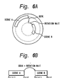
- Figs. 6A and 6B show an edit operation for an A/V signal on the hard disk.
- scenes A and B are recorded on an outer peripheral track and an inner peripheral track of the hard disk, respectively.
- data of the scene A is read and reproduced with a track number and a sector number that represent the position of the scene A.
- the seek operation and the rotation wait operation are performed with a track number and a sector number that represent the position of the scene B.
- the scene B is read and reproduced.
- the edit operation for connecting the scenes A and B and for recording the connected scenes on the tape is not performed.
- points A start and A end that represent the start position and the end position of the scene A and points B start and B end that represent the start position and the end position of the scene B are recorded.
- the seek operation and the rotation wait operation are performed.
- data from the point B start to the point B end is reproduced.
- the seek operation and the rotation wait operation performed from the scene A to the scene B take several 10 ms to several 100 ms. This time period is much smaller than that necessary for such operations on the linear record medium.
- discontinuous data can be continuously reproduced without need to perform the edit operation for connecting scenes.
- an A/V signal can be successively reproduced. Consequently, with a non-linear record medium such as a hard disk, the edit operation can be much effectively performed.
- an audio signal with multiple channels has been increasingly used.
- an audio signal with four to eight channels has been recorded.
- an audio signal is recorded in such a manner that a voice sound is recorded on the first channel, other sounds are recorded on the second and third channels, and an effect sound is recorded on the fourth channel.
- various audio signals and video signals are recorded in one hard disk drive.
- Such audio signals and video signals may be edited as one A/V signal.
- the seek operation should be performed for each of audio channels, the number of times of the seek operation and the seek distance increase. Thus, it is difficult to successively reproduce such signals as one A/V signal.
- Figs. 7A and 7B are schematic diagrams showing a method for recording audio signals and video signals to respective hard disk drives.
- this method as shown in Fig. 7A, only video signals are recorded to a hard disk drive A.
- audio signals with four channels (first to fourth channels) are recorded to a hard disk drive B.
- Figs. 8A and 8B are schematic diagrams showing a method for recording relevant audio signals and video signals as blocks.
- this method as shown in Fig. 8A, when a video signal is associated with an audio signal with four channels (first to fourth channels), these signals are recorded as a block.
- the edit point of the audio signal is the same as the edit point of the video signal.
- the number of times of the seek operation for the hard disk drive is small.
- the signals can be effectively edited.
- A/V signals are simply reproduced in succession, the reproduction speed increases.
- an A/V signal recording/reproducing apparatus that has the advantages of the above-described two methods that allow the parallel reproductions of audio signals and video signals using two hard disk drives and high speed successive reproductions of which relevant audio signals and video signals are recorded as blocks and that is accomplished at low cost has not be developed.
- An embodiment of the present, invention can provide a recording apparatus as defined in independent claim 1 for recording an input video signal and an audio signal on a record medium that is randomly accessible, comprising a control means for causing the audio signal to be recorded to a predetermined region disposed in the track direction of the record medium when the video signal and the audio signal are recorded on the record medium, and a record means for recording the video signal and the audio signal on the same record medium under the control of the control means.
- An embodiment of the present invention also provides a reproducing apparatus as defined in independent claim 8 for reproducing an audio signal and a video signal corresponding thereto from a record medium that is randomly accessible, the audio signal and the video signal having been recorded on the record medium, the audio signal having been recorded in a predetermined region independently disposed in the track direction of the record medium, comprising a control means for causing the video signal and the audio signal recorded in the predetermined region to be reproduced when the video signal and the audio signal recorded on the record medium are reproduced, and a reproduction means for reproducing the video signal and the audio signal from the record medium under the control of the control means and reproducing the audio signal from the predetermined region under the control of the control means when the audio signal is independently reproduced.
- An embodiment of the present invention also provides a recording/reproducing apparatus as defined in independent claim 14 for recording an input video signal and an input audio signal on a record medium that is randomly accessible and reproducing the video signal and audio signal therefrom, comprising a record control means for causing the video signal and the audio signal to be recorded in a first region and the a second region, respectively, the second region being disposed in the track direction of the first region of the record medium, a record means for recording the video signal and the audio signal on the same record medium under the control of the record control means, a reproduction control means for causing the audio signal to be reproduced from the second region when the audio signal and the video signal are independently reproduced from the record medium recorded by the record means, and a reproduction means for reproducing the video signal and the audio signal from the record medium under the control of the reproduction control means and reproducing the audio signal from the second region under the control of the reproduction control means when the audio signal is independently reproduced.
- An embodiment of the present invention yet further provides a recording method as defined in claim 15 for recording an input video signal and an audio signal on a record medium that is randomly accessible, comprising the steps of (1) causing the audio signal to be recorded to a predetermined region disposed in the track direction of the record medium when the video signal and the audio signal are recorded on the record medium, and (2) recording the video signal and the audio signal on the same record medium corresponding to the step (1).
- An embodiment of the present invention provides a reproducing method as defined in independent claim 22 for reproducing an audio signal and a video signal corresponding thereto from a record medium that is randomly accessible, the audio signal and the video signal having been recorded on the record medium, the audio signal having been recorded in a predetermined region independently disposed in the track direction of the record medium, comprising the steps of (1) causing the video signal and the audio signal recorded in the predetermined region to be reproduced when the video signal and the audio signal recorded on the record medium are reproduced, and (2) reproducing the video signal and the audio signal from the record medium by the step (1) and reproducing the audio signal from the predetermined region by the step (1) when the audio signal is independently reproduced.
- An embodiment of the present invention provides a recording/reproducing method as defined in independent claim 28 for recording an input video signal and an input audio signal on a record medium that is randomly accessible and reproducing the video signal and audio signal therefrom, comprising the steps of (1) causing the video signal and the audio signal to be recorded in a first region and the a second region, respectively, the second region being disposed in the track direction of the first region of the record medium, (2) recording the video signal and the audio signal on the same record medium by the step (1), (3) causing the audio signal to be reproduced from the second region when the audio signal and the video signal are independently reproduced from the record medium recorded by the step (2), and (4) reproducing the video signal and the audio signal from the record medium by the step (3) and reproducing the audio signal from the second region by the step (3) when the audio signal is independently reproduced.
- An embodiment of the present invention yet further provides a record medium as defined in independent claim 29 on which an input video signal and an input audio signal are recorded and from which the input video signal and the input audio signal are reproduced, the input video signal and the input audio signal being randomly accessible on the record medium, wherein a predetermined amount of the . video signal and a predetermined amount of the audio signal corresponding thereto are adjacently recorded or reproduced on/from a first region, the audio signal being recorded or reproduced on/from a second region disposed in the track direction of the first region of the record medium.
- a preferred form of implementation of the present invention described below provides an A/V signal recording apparatus and method that allow the number of times a seek operation is preferred to be decreased and allow A/V signals recorded on the same non-linear disk record medium to be successively reproduced so that the video signals and audio signals cam be edited independently.
- the seek distance between individual channels of audio signals can be decreased, thereby decreasing the seek time.
- Fig. 1 is a block diagram showing a structure of an A/V signal recording apparatus embodying the present invention and an A/V signal editing system associated therewith.
- a portion surrounded by dotted lines is an A/V signal recording apparatus 1.
- a command for causing the A/V signal recording apparatus to record/reproduce an A/V signal is supplied from the outside thereof to a system controller 10 through an interface such as RS-422 interface.
- the command is supplied from the system controller 10 to a CPU 11.
- the CPU 11 controls a disk format converter 12, a disk format restoring unit 13, a buffer memory controller 14, and a SCSI controller 15.
- the buffer memory controller 14 controls data write/read address and timings of data write/read operations of the buffer memory 16.
- a hard disk drive 17 has a SCSI interface.
- the SCSI controller 15 controls data write/read addresses such as track numbers and sector numbers of the hard disk drive 17.
- the hard disk drive 17 is controlled corresponding to the CVA (Constant Angular Velocity) method of which data is read at a constant angular velocity of the disk.
- the hard disk drive 17 may be controlled corresponding to the zone CAV method of which the disk is radially zoned and data rate is circumferentially increased.
- the disk format converter 12 converts a supplied digital signal into a format for the hard disk drive 17 under the control of the CPU 11.
- the disk format restoring unit 13 restores the digital signal read from the hard disk drive 17 and supplied through the SCSI controller 15 and the buffer memory 16 under the control of the CPU 11 into the original format.
- An A/V editor 20 is composed of for example a computer.
- the A/V editor 20 has a user interface composed of I/O devices (such as a mouse and a keyboard) and a display.
- the A/V editor 20 inputs/outputs an A/V signal to/from an external device and the A/V signal recording apparatus and causes the A/V signal recording apparatus 1 to record/reproduce the A/V signals through the system controller 10 connected with for example the RS-422 interface.
- the A/V editor 20 is connected to a monitor 21 so as to display A/V signals received from the A/V signal recording apparatus 1.
- an external A/V signal can be recorded to the A/V signal recording apparatus 1 or an A/V signal recorded in the A/V signal recording apparatus can be edited.
- the user edits an A/V signal he or she can designate an edit point thereof to the A/V editor 20 through the user interface while watching a picture read from the A/V signal recording apparatus 1 and displayed on the monitor 21 and listening to a sound reproduced by a sound reproducing apparatus.
- An A/V signal is recorded to the A/V signal recording apparatus in the following manner.
- the A/V editor 20 sends a command to the system controller 10 so that a designated A/V signal is recorded to the hard disk drive 17 of the A/V signal recording apparatus 1.
- the system controller 10 sends a command to the CPU 11 so as to control the disk format converter 12, the buffer memory controller 14, and the SCSI controller 15.
- the A/V signal to be recorded is supplied from the A/V editor 20 to the encoder 18.
- the A/V signal is a digital signal of which a video signal and an audio signal are serially supplied.
- the encoder 18 performs predetermined signal processes (such as 8/10 converting process and compressing encoding process) for the supplied A/V signal.
- the resultant signal is supplied to the disk format converter 12.
- the disk format converter 12 converts the supplied A/V signal into the format for the hard disk drive 17 under the control of the CPU 11.
- An audio signal with for example four channels is divided corresponding to every two frames of a video signal.
- the divided portions of the audio signal and the two frames of the video signal compose one GOP (Group Of Picture).
- GOP Group Of Picture
- the data length of each sector of the hard disk drive 17 is for example 4096 bytes
- one GOP of a video signal corresponding to the NTSC system is assigned 42 sectors.
- One GOP of a video signal corresponding to the PAL system is assigned 48 sectors.
- One GOP of each channel of an audio signal is assigned two sectors.
- the resultant A/V signal is supplied to the buffer memory 16.
- the buffer memory controller 14 causes the A/V signal to be stored in a predetermined region of the buffer memory 16 under the control of the CPU 11.
- the buffer memory controller 14 causes the A/V signal to be read from the buffer memory 16 at a predetermined timing under the control of the CPU 11.
- the A/V signal read from the buffer memory 16 is recorded to the hard disk drive 17 through the SCSI controller 15.
- the SCSI controller 15 controls the hard disk drive 17 under the control of the CPU 11 and records the A/V signal to a predetermined region of the hard disk drive 17.
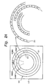
- Fig. 2A shows an example of a record region for A/V signals on a record medium 30 of the hard disk drive 17.
- the record medium 30 is divided into an audio region 31 and a video region 32 in the track direction. Audio signals of A/V signals are recorded in the audio region 31. Video signals of A/V signals are recorded in the video region 32. Audio signals are grouped as GOPs. As shown in Fig. 2A, audio signals and video signals can be recorded on a plurality of tracks of the respective regions.
- the data amount of an audio signal that requires two sectors for each channel of one GOP is much smaller than the data amount of a video signal that requires 42 sectors of one GOP in the NTSC system and 48 sectors of one GOP in the PAL system.
- the audio region 31 takes a smaller width (tracks) of the record medium 30 of the hard disk drive 17 than the video region 32.
- the user issues a command to the A/V editor 20 so as to read an A/V signal written to the hard disk drive 17 of the A/V signal recording apparatus 1.
- the user issues a command to the A/V editor 20 so as to read a predetermined A/V signal and edit the A/V signal recorded on the record medium 30 of the hard disk drive 17.
- the A/V editor 20 sends a command to the system controller 10 so as to read the A/V signal.
- the system controller 10 sends a command to the CPU 11 so as to control the disk format restoring device 13, the buffer memory controller 14, and the SCSI controller 15.
- the A/V signal is read from the hard disk drive 17 under the control of the SCSI controller 15.
- Fig. 2B shows a read operation of a video signal and an audio signal from the record medium 30 shown in Fig 2A in the case that the edit point of the audio signal is different from the edit point of the video signal and the audio signal and that the audio signal and the video signal are independently edited.
- the magnetic head (not shown) of the hard disk drive 17 is moved to the video region 32 under the control of the SCSI controller 15.
- One GOP (in this example, VIDEO1) of the video signal is read from the video region 32.
- the magnetic head seeks the audio region 31 from the video region 32.
- the seek operation is performed three times from A1 to A2', from A2' to A3", and from A3" to A4.
- the magnetic head seeks the video region 32 from the audio region 31. In such a manner, different tracks may be sought in the same region 31.
- the magnetic head reads for example VIDEO2 from the video region 32.
- the magnetic head After VIDEO2 has been read, the magnetic head seeks the audio region 31 from the video region. Likewise, the magnetic head performs the seek operation three times from A1" to A2, from A2 to A3', and from A3' to A4".
- the seek operation is performed five times.
- the width of the audio region 31 of the record medium 30 of the hard disk drive is smaller than that of the video region 32 thereof.
- the seek distance in the audio region 31 is small. Consequently, the seek operation performed three times in the audio region 31 takes a shorter time than the seek operation performed twice between the video region 32 and the audio region 31.
- the seek distance and seek time can be remarkably decreased than before.
- Fig. 2C shows a read operation of an audio signal and a video signal from the record medium 30 in the case that the audio signal and the video signal are edited for each GOP and that the edit point of the audio signal is the same as the edit point of the video signal.
- the magnetic head should perform the seek operation between an audio signal and a video signal.
- the A/V signal read from the hard disk drive 17 is supplied to the buffer memory 16.
- the buffer memory controller 14 causes the A/V signal to be stored in a predetermined region of the buffer memory 16 under the control of the CPU 11.
- the buffer memory controller 14 causes the A/V signal to be read from the buffer memory 16 at a predetermined timing under the control of the CPU 11. This timing is controlled so that the time difference of the seek operation for the A/V signal read from the hard disk drive 17 is compensated and the A/V signal corresponding to the original GOP is obtained.
- the A/V signal read from the buffer memory 16 is supplied to the disk format restoring unit 13 controlled by the CPU 11.
- the disk format restoring unit 13 restores the GOP format corresponding to the sectors of the record medium 30 of the hard disk drive 17 into an A/V signal of video signals and audio signals that are serially sent.
- the restored A/V signal is supplied to the decoder 19.
- the decoder 19 performs reverse conversions as those performed in the encoder 18 (namely, the decoder 19 performs decoding operation and 10/8 converting operation).
- the resultant A/V signal is supplied to the A/v editor 20.
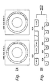
- Fig. 3A shows an example of a record region of an A/V signal on the record medium 30 of the hard disk drive 17.
- an audio/video region 32' is disposed.
- a video signal and an audio signal are grouped for each GOP.
- an audio signal for each channel is written to the audio region 31.
- the audio signal may be written to a plurality of tracks.
- the structure of the A/V signal recording apparatus 1 according to the second embodiment of the present invention is the same as that according to the first embodiment of the present invention. Thus, for simplicity, the description of signal processes in the A/V signal recording apparatus 1 is omitted.
- Fig. 3B shows a read operation of an audio signal and a video signal read from the record medium 30 shown in Fig. 3A in the case that the audio signal and the video signal are independently edited.
- the magnetic head of the hard disk drive 17 is moved to the audio/video region 32'.
- One GOP of the video signal is read from the audio/video region 32'.
- the magnetic head seeks the audio region 31 so as to read a designated audio signal for each channel.
- an audio signal can be read in a short seek time.
- the magnetic head when an audio signal and a video signal are independently edited, since the magnetic head seeks the audio region 31 that has a limited track width, the seek distance and seek time can be remarkably decreased in comparison with those of the previously proposed apparatuses.
- Fig. 3C shows a read operation of an audio signal and a video signal read from the record medium 30 in the case that the edit point of the audio signal is the same as the edit point of the video signal and that the audio signal and the video signal are edited for each GOP.
- the magnetic head seeks only the audio/video region 32' in which GOPs are not successive.
- audio signals A1, A2, A3, and A4 are read.
- the magnetic head seeks the audio/video region 32' and reads a video signal VIDEO' and then audio signals A1', A2', A3', and A4'. Thereafter, the magnetic head seeks the audio/video region 32' and reads a VIDEO' signal and so forth.
- the number of times of the seek operation is very small.
- A/V signals can be easily reproduced in succession.
- A/V signals When A/V signals are successively reproduced, not edited, they can be successively read from the audio/video region 32'. Thus, since it is not necessary to perform the seek operation, the A/V signals can be transferred at a higher speed several times than the speed of the real reproducing operation.
- audio signals are redundantly written to both the audio/video region 32' and the audio region 31.
- the number of sectors required for audio signals is much smaller than that for video signals.
- the loss of the storage capacity of the record medium 30 can be ignored.
- the audio region 31 is disposed outside the video region 32 or the audio/video region 32'.
- the present invention is not limited to such a structure.
- the audio region 31 may be disposed inside the region 32 or 32'.
- a plurality of audio regions 30 and video regions 32 or audio/video regions 32' may be alternatively disposed on the record medium 30.
- A/V signals that are input/output to/from the A/V signal recording apparatus 1 are digital signals.
- the present invention is not limited to such an example.
- analog signals can be input/output.
- A/V signals are recorded to the record medium 30 of the hard disk drive 17.
- the present invention is not limited to such an example. Instead, another record medium such as an MO disc (magnetic optical disc) can be used as long at it can non-linearly record A/V signals.
- MO disc magnetic optical disc
- a region for only audio signals is disposed on a record medium in addition to a region for audio signals and video signals.
- an audio signal has many channels
- that video signals and audio signals are independently edited, and that the magnetic head of the hard disk drive should seek each channel of the audio signals, the seek distance and seek time are small.
- A/V signals can be easily reproduced in succession.
- a region for only audio signals is disposed on a record medium in addition to a region for audio signals and video signals.
- both requirements of independent edit operations of audio signals and video signals and high speed successive read operation that are not impossible with the previously preferred apparatuses can be accomplished at relatively low cost.
Landscapes
- Engineering & Computer Science (AREA)
- Multimedia (AREA)
- Signal Processing (AREA)
- Signal Processing For Digital Recording And Reproducing (AREA)
- Management Or Editing Of Information On Record Carriers (AREA)
- Television Signal Processing For Recording (AREA)
Claims (56)
- Aufzeichnungsvorrichtung zum Aufzeichnen eines Eingangsvideosignals und eines Eingangsaudiosignals, welches mehrere Audiokanäle aufweist, auf einem Plattenträger (30), auf den wahlfrei zugegriffen werden kann, welche aufweist:dadurch gekennzeichnet, dasseine Aufzeichnungseinrichtung (17), um das Videosignal und das Audiosignal auf dem gleichen Plattenträger (30) unter der Steuerung einer Steuerungseinrichtung (11) aufzuzeichnen, wobei die Steuerungseinrichtung (11) veranlasst, dass die Aufzeichnungseinrichtung (17) das Audiosignal in einem vorher festgelegten Audiobereich (31), der in der Spurrichtung des Plattenträgers (30) angeordnet ist, und das Videosignal in einem vorher festgelegten Videobereich (32), der in der Spurrichtung des Plattenträgers (30) angeordnet ist, aufzeichnet;
der Audiobereich (31) auf einem äußeren Bereich der Platte und der Videobereich (32) auf einem inneren Bereich der Platte gebildet ist, wobei die Audio- und Videosignale in konzentrischen Spuren aufgezeichnet sind und jeder Kanal des Audiosignals in zumindest einer Spur des Audiobereichs (31) aufgezeichnet ist. - Aufzeichnungsvorrichtung nach Anspruch 1, wobei die Steuerungseinrichtung (11) veranlasst, dass das Audiosignal in einem vorher festgelegten Bereich in einem konzentrischen Kreis mit einer vorher festgelegten Spurbreite in der Spurrichtung des Plattenträgers (30) aufgezeichnet wird.
- Aufzeichnungsvorrichtung nach Anspruch 1, wobei die Steuerungseinrichtung (11) veranlasst, dass das Videosignal und das Audiosignal im Videobereich (32) auf dem Plattenträger (30) so aufgezeichnet werden, dass eine vorher festgelegte Menge des Audiosignals benachbart zu einer vorher festgelegten Menge des Videosignals angeordnet ist, und das Audiosignal im Audiobereich (31) auf dem Plattenträger (30) redundant aufgezeichnet wird.
- Aufzeichnungsvorrichtung nach Anspruch 3, wobei das Videosignal und das Audiosignal mit einer Bildgruppe verknüpft sind.
- Aufzeichnungsvorrichtung nach Anspruch 1, welche außerdem aufweist:eine Formatumsetzungseinrichtung (12), um das Eingangsvideosignal und das Eingangsaudiosignal in ein Format für den Plattenträger (30) umzusetzen und um die resultierenden Signale an die Steuerungseinrichtung (11) auszugeben.
- Aufzeichnungsvorrichtung nach Anspruch 1, welche weiter aufweist:eine Kompressionseinrichtung (18) zum Kompressions-Codieren des Eingangsvideosignals und des Eingangsaudiosignals und zum Ausgeben des resultierenden Videosignals und des Audiosignals an die Steuerungseinrichtung (11).
- Aufzeichnungsvorrichtung nach Anspruch 1, die außerdem aufweist:eine Kompressionseinrichtung (18) zum Kompressions-Codieren lediglich des Eingangssignals und zum Ausgeben des resultierenden Videosignals und des Audiosignals an die Steuerungseinrichtung (11).
- Wiedergabevorrichtung zum Reproduzieren eines Audiosignals, welches mehrere Audiokanäle aufweist, und eines Videosignals, welches diesem entspricht, von einem Plattenträger (30), auf den wahlfrei zugegriffen werden kann, wobei das Audiosignal und das Videosignal auf dem Plattenträger (30) durch die Aufzeichnungsvorrichtung aufgezeichnet wurde, nach einem der Ansprüche 1 bis 7, wobei das Videosignal in einem vorher festgelegten Videobereich (32) aufgezeichnet wurde, der in der Spurrichtung des Trägers angeordnet ist, und das Audiosignal in einem vorher festgelegten Audiobereich (31), der unabhängig angeordnet wurde, in der Spurrichtung des Plattenträgers (30) aufgezeichnet wurde, welche aufweist:wobei die Steuerungseinrichtung (11) veranlasst, dass die Wiedergabeeinrichtung (1) das Videosignal, welches im vorher festgelegten Videobereich (32) aufgezeichnet wurde, und das Audiosignal, welches im vorher festgelegten Audiobereich (31) aufgezeichnet wurde, unabhängig reproduziert; dadurch gekennzeichnet, dasseine Wiedergabeeinrichtung (17) zum Reproduzieren des Videosignals und des Audiosignals vom Plattenträger (30) unter der Steuerung einer Steuerungseinrichtung (11) und zum Reproduzieren des Audiosignals von dem vorher festgelegten Audiobereich (31) unter der Steuerung der Steuerungseinrichtung (11), wenn das Audiosignal unabhängig reproduziert wird,
der Audiobereich (31) von einem äußeren Bereich der Platte reproduziert wird und der Videobereich (32) von einem inneren Bereich der Platte reproduziert wird, wobei die Audio- und Videosignale von konzentrischen Spuren reproduziert werden und wobei jeder Kanal des Audiosignals von zumindest einer Spur der konzentrischen Spuren im Audiobereich (31) reproduziert wird. - Wiedergabevorrichtung nach Anspruch 8,
wobei die Steuerungseinrichtung (11) mit einer externen Editiereinheit verbunden ist, ein Steuerungssignal davon empfängt und veranlasst, dass das Audiosignal und das Videosignal unabhängig vom Plattenträger (30) entsprechend dem Steuerungssignal reproduziert werden. - Wiedergabevorrichtung nach Anspruch 8, welche außerdem aufweist:eine Formatwiederherstellungseinrichtung (13) zum Wiederherstellen des Videosignals und des Audiosignals für das Format für den Plattenträger (30), welches durch die Wiedergabeeinrichtung (17) unter der Steuerung der Steuerungseinrichtung (11) reproduziert wird, in ein Videosignal und ein Audiosignal, die seriell geliefert werden.
- Wiedergabevorrichtung nach Anspruch 8, welche außerdem aufweist:eine Decodiereinrichtung (19) zum Decodieren des kompressions-codierten Audiosignals und/oder Videosignals, die von der Wiedergabeeinrichtung (17) empfangen werden, und zum Ausgeben des resultierenden Signals.
- Wiedergabevorrichtung nach Anspruch 8, wobei eine vorher festgelegte Menge des Videosignals benachbart zu einer vorher festgelegten Menge des Audiosignals in einem Videobereich (32) des Plattenträgers (30) aufgezeichnet wurde, das Audiosignal redundant in einem Audiobereich (31 ) aufgezeichnet wurde, der unabhängig in der Spurrichtung des Videobereichs (32) des Plattenträgers (30) angeordnet ist, und
die Steuerungseinrichtung (11) bewirkt, dass die Wiedergabeeinrichtung (17) das Videosignal und das Audiosignal, die benachbart auf dem Plattenträger (30) aufgezeichnet wurden, reproduziert und das Audiosignal vom Audiobereich (31) reproduziert, wenn das Videosignal und das Audiosignal unabhängig reproduziert werden. - Wiedergabevorrichtung nach Anspruch 12, wobei das Videosignal und das Audiosignal mit einer Bildgruppe verknüpft sind.
- Aufzeichnungs-/Wiedergabevorrichtung zum Aufzeichnen eines Eingangsvideosignals und eines Eingangsaudiosignals, das mehrere Audiokanäle aufweist, auf einem Plattenträger (30), auf den wahlfrei zugegriffen werden kann, und zum Reproduzieren des Videosignals und des Audiosignals davon, welche aufweist:die Aufzeichnungsvorrichtung nach einem der Ansprüche 1 bis 7 und die Wiedergabevorrichtung nach einem der Ansprüche 8 bis 13.
- Aufzeichnungsverfahren zum Aufzeichnen eines Eingangsvideosignals und eines Eingangsaudiosignals, das mehrere Audiokanäle aufweist, auf einem Plattenträger (30), auf den wahlfrei zugegriffen werden kann, welches folgende Schritte aufweist:der Audiobereich (31) auf dem äußeren Bereich der Platte und der Videobereich (32) auf inneren Bereich der Platte gebildet ist, die Audio- und Videosignale in konzentrischen Spuren aufgezeichnet sind und jeder Kanal des Audiosignals in zumindest einer Spur des Audiobereichs (31) aufgezeichnet ist.(1) Aufzeichnen des Videosignals und des Audiosignals auf dem gleichen Plattenträger (30); und(2) Veranlassen, dass das Audiosignal in einem vorher festgelegten Audiobereich (31) aufgezeichnet wird, der in der Spurrichtung des Plattenträgers (30) angeordnet ist, und dass das Videosignal in einem vorher festgelegten Videobereich (32), der in der Spurrichtung des Plattenträgers (30) angeordnet ist, aufgezeichnet wird; wobei
- Aufzeichnungsverfahren nach Anspruch 15,
wobei der Schritt (2) dadurch durchgeführt wird, dass veranlasst wird, dass das Audiosignal in einem vorher festgelegten Bereich in einem konzentrischen Kreis mit einer vorher festgelegten Spurbreite in der Spurrichtung des Plattenträgers (30) aufgezeichnet wird. - Aufzeichnungsverfahren nach Anspruch 15,
wobei der Schritt (2) dadurch durchgeführt wird, dass bewirkt wird, dass das Videosignal und das Audiosignal im Videobereich (32) auf dem Plattenträger (30) aufgezeichnet werden, so dass eine vorher festgelegte Menge des Audiosignals benachbart zu einer vorher festgelegten Menge des Videosignals angeordnet ist und das Audiosignal im Audiobereich (31) auf dem Plattenträger (30) redundant aufgezeichnet wird. - Aufzeichnungsverfahren nach Anspruch 17, wobei das Videosignal und das Audiosignal mit einer Bildgruppe verknüpft sind.
- Aufzeichnungsverfahren nach Anspruch 15, welches außerdem folgenden Schritt aufweist:Umsetzen des Eingangsvideosignals und des Eingangsaudiosignals in ein Format für den Plattenträger (30) und Ausgeben der resultierenden Signale, um den Schritt (2) auszuführen.
- Aufzeichnungsverfahren nach Anspruch 15, welches außerdem folgenden Schritt aufweist:Kompressions-Codieren des Eingangsvideosignals und des Eingangsaudiosignals und Ausgeben des resultierenden Videosignals und des Audiosignals, um den Schritt (2) auszuführen.
- Aufzeichnungsverfahren nach Anspruch 15, welches außerdem folgenden Schritt aufweist:Kompressions-Codieren lediglich des Eingangsvideosignals und Ausgeben des resultierenden Videosignals, um den Schritt (2) auszuführen.
- Wiedergabeverfahren zum Reproduzieren eines Audiosignals, welches mehrere Audiokanäle aufweist, und eines Videosignals, welches diesem entspricht, von einem Plattenträger (30), auf den wahlfrei zugegriffen werden kann, wobei das Audiosignal und das Videosignal auf dem Plattenträger (30) durch die Aufzeichnungsvorrichtung aufgezeichnet wurden, nach einem der Ansprüche 1 bis 7, wobei das Videosignal in einem vorher festgelegten Videobereich (32) aufgezeichnet wurde, der in der Spurrichtung des Trägers angeordnet ist, und das Audiosignal in einem vorher festgelegten Audiobereich (31) aufgezeichnet wurde, der unabhängig in der Spurrichtung des Plattenträgers (30) angeordnet ist, welches folgende Schritte aufweist:das Reproduzieren das Reproduzieren des Audiosignals vom äußeren Bereich der Platte und des Videobereichs von einem inneren Bereich der Platte umfasst, wobei die Audiound Videosignale von konzentrischen Spuren reproduziert werden und jeder Kanal des Audiosignals von zumindest einer Spur der konzentrischen Spuren im Audiobereich (31) reproduziert wird.(1) Reproduzieren des Videosignals und des Audiosignals vom Plattenträger (30) und Reproduzieren des Audiosignals vom vorher festgelegten Audiobereich (31) unabhängig,(2) Veranlassen, dass das Videosignal, welches im vorher festgelegten Videobereich (32) aufgezeichnet wurde und das Audiosignal, welches im vorher festgelegten Audiobereich (31) aufgezeichnet wurde, reproduziert werden, wenn das Videosignal und das Audiosignal, welche auf dem Plattenträger (30) aufgezeichnet wurden, unabhängig reproduziert werden; wobei
- Wiedergabeverfahren nach Anspruch 22,
wobei der Schritt (2) dadurch durchgeführt wird, dass ein Steuerungssignal von einer externen Editiereinheit empfangen wird, um zu veranlassen, dass das Audiosignal und das Videosignal unabhängig vom Plattenträger (30) entsprechend dem Steuerungssignal reproduziert werden. - Wiedergabeverfahren nach Anspruch 22, welches außerdem folgenden Schritt aufweist:Wiederherstellen des Videosignals und des Audiosignals im Format für den Plattenträger (30), welche durch den Schritt (1) reproduziert wurden, in ein Videosignal und ein Audiosignal, welches seriell geliefert wird.
- Wiedergabeverfahren nach Anspruch 22, welches außerdem folgenden Schritt aufweist:Decodieren des kompressions-codierten Audiosignals und/oder Videosignals, die durch den Schritt (2) empfangen wurden, und Ausgeben des resultierenden Signals.
- Wiedergabeverfahren nach Anspruch 22 zum Reproduzieren eines Audiosignals, welches mehrere Audiokanäle aufweist, und eines dazu entsprechenden Videosignals von einem Plattenträger (30), auf den wahlfrei zugegriffen werden kann, wobei eine vorher festgelegte Menge des Videosignals benachbart zu einer vorher festgelegten Menge des Audiosignals in einem Videobereich (32) des Plattenträgers (30) aufgezeichnet wurde, wobei das Audiosignal redundant in einem Audiobereich (31) aufgezeichnet wurde, der unabhängig in der Spurrichtung des Videobereichs (32) des Plattenträgers (30) angeordnet ist, welches folgende Schritte aufweist:(1) Reproduzieren des Videosignals und des Audiosignals vom Videobereich (32) und Reproduzieren des Audiosignals vom Audiobereich (31), wenn das Audiosignal unabhängig reproduziert wird;(2) Veranlassen, dass das Videosignal und das Audiosignal, die benachbart auf dem Plattenträger (30) aufgezeichnet wurden, reproduziert werden, und Reproduzieren des Videosignals vom Videobereich (32) und des Audiosignals vom Audiobereich (31), wenn das Videosignal und das Audiosignal unabhängig reproduziert werden.
- Wiedergabeverfahren nach Anspruch 22, wobei das Videosignal und das Audiosignal mit einer Bildgruppe verknüpft sind.
- Aufzeichnungs-/Wiedergabeverfahren, welches die Aufzeichnungsschritte nach einem der Ansprüche 15 bis 21 und die Wiedergabeschritte nach einem der Ansprüche 22 bis 30 aufweist.
- Plattenträger (30), auf welchem ein Eingangsvideosignal und ein Eingangsaudiosignal, das mehrere Audiokanäle aufweist, durch die Aufzeichnungsvorrichtung nach einem der Ansprüche 1 bis 8 aufgezeichnet wurden.
- Aufzeichnungsverfahren nach Anspruch 27,
wobei der Schritt (1) dadurch durchgeführt wird, dass veranlasst wird, dass das Eingangsvideosignal und das Ausgangsvideosignal auf dem Aufzeichnungsträger aufgezeichnet werden, so dass das Videosignal in einem Bereich aufgezeichnet wird, der vom vorher festgelegten Bereich für das Audiosignal verschieden ist. - Aufzeichnungsverfahren nach Anspruch 27, welches außerdem folgenden Schritt aufweist:Umsetzen des Eingangsvideosignals und des Eingangsaudiosignals in ein Format für den Aufzeichnungsträger und Ausgeben der resultierenden Signale, um den Schritt (1) auszuführen.
- Aufzeichnungsverfahren nach Anspruch 27, welches außerdem folgenden Schritt aufweist:Kompressions-Codieren des Eingangsvideosignals und des Eingangsaudiosignals und Ausgeben des resultierenden Videosignals und des Audiosignals, um den Schritt (1) durchzuführen.
- Aufzeichnungsverfahren nach Anspruch 27, welches außerdem folgenden Schritt aufweist:Kompressions-Codieren lediglich des Eingangsvideosignals und Ausgeben des resultierenden Videosignals, um den Schritt (1) durchzuführen.
- Wiedergabeverfahren zum Reproduzieren eines Audiosignals und eines Videosignals entsprechend dazu von einem Aufzeichnungsträger, auf den wahlfrei zugegriffen werden kann, wobei das Audiosignal und das Videosignal auf dem Aufzeichnungsträger aufgezeichnet wurden, das Audiosignal in einem vorher festgelegten Bereich aufgezeichnet wurde, der unabhängig in der Spurrichtung des Aufzeichnungsträgers angeordnet ist, welches folgende Schritte aufweist:(1) Veranlassen, dass das Videosignal und das Audiosignal, die im vorher festgelegten Bereich aufgezeichnet wurden, reproduziert werden, wenn das Videosignal und das Audiosignal, welche auf dem Aufzeichnungsträger aufgezeichnet wurden, reproduziert werden; und(2) Reproduzieren des Videosignals und des Audiosignals vom Aufzeichnungsträger durch den Schritt ( 1 ) und Reproduzieren des Audiosignals vom vorher festgelegten Bereich durch den Schritt (1), wenn das Audiosignal unabhängig reproduziert wird.
- Wiedergabeverfahren nach Anspruch 34, wobei der Schritt (1) durch Empfangen eines Steuerungssignals von einer externen Editiereinheit durchgeführt wird, um zu veranlassen, dass das Audiosignal und das Videosignal unabhängig vom Aufzeichnungsträger entsprechend dem Steuerungssignal reproduziert werden.
- Wiedergabeverfahren nach Anspruch 34, welches außerdem folgenden Schritt aufweist:Wiederherstellen des Videosignals und des Audiosignals im Format für den Aufzeichnungsträger, der durch den Schritt (2) reproduziert wurde, in ein Videosignal und ein Audiosignal, das seriell geliefert wird.
- Wiedergabeverfahren nach Anspruch 34, welches den Schritt aufweist:Decodieren des kompressions-codierten Audiosignals und/oder Videosignals, die durch den Schritt (1) empfangen wurden und Ausgeben des resultierenden Signals.
- Wiedergabeverfahren zum Reproduzieren eines Audiosignals und eines Videosignals entsprechend dazu von einem Aufzeichnungsträger, auf den wahlfrei zugegriffen werden kann, wobei eine vorher festgelegte Menge des Videosignals benachbart zu einer vorher festgelegten Menge des Audiosignals in einem ersten Bereich des Aufzeichnungsträgers aufgezeichnet wurde, wobei das Audiosignal in einem zweiten Bereich aufgezeichnet wurde, der unabhängig in der Spurrichtung des ersten Bereichs des Aufzeichnungsträgers angeordnet ist, welches folgende Schritte aufweist:(1) Veranlassen, dass das Videosignal und das Audiosignal, welche benachbart auf dem Aufzeichnungsträger aufgezeichnet sind, reproduziert werden, und Reproduzieren des Videosignals vom ersten Bereich und des Audiosignals vom zweiten Bereich, wenn das Videosignal und das Audiosignal unabhängig reproduziert werden; und(2) Reproduzieren des Videosignals und des Audiosignals vom ersten Bereich und Reproduzieren des Audiosignals vom zweiten Bereich durch den Schritt (1), wenn das Audiosignal unabhängig reproduziert wird.
- Wiedergabeverfahren nach Anspruch 38, wobei der Schritt (1) durch Empfangen eines Steuerungssignals von einer externen Editiereinheit durchgeführt wird und das Videosignal und das Audiosignal, die auf dem Aufzeichnungsträger aufgezeichnet sind, entsprechend dem Steuerungssignal unabhängig reproduziert werden.
- Wiedergabeverfahren nach Anspruch 38, welches den Schritt aufweist:Wiederherstellen des Videosignals und des Audiosignals im Format für den Aufzeichnungsträger, der durch den Schritt (2) reproduziert wurde, in ein Videosignal und in ein Audiosignal, welches seriell geliefert wird.
- Wiedergabeverfahren nach Anspruch 38, welches außerdem folgenden Schritt aufweist:Decodieren des kompressions-codierten Audiosignals und/oder Videosignals durch den Schritt (2) und Ausgeben des resultierenden Signals.
- Aufzeichnungs-/Wiedergabeverfahren zum Aufzeichnen eines Eingangsvideosignals und eines Eingangsaudiosignals auf einem Aufzeichnungsträger, auf den wahlfrei zugegriffen werden kann, und Reproduzieren des Videosignals und des Audiosignals davon, welches folgende Schritte aufweist:(1) Veranlassen, dass das Videosignal und das Audiosignal in einem ersten Bereich bzw. einem zweiten Bereich aufgezeichnet werden, wobei der zweite Bereich in der Spurrichtung des ersten Bereichs des Aufzeichnungsträgers angeordnet ist;(2) Aufzeichnen des Videosignals und des Audiosignals auf dem gleichen Aufzeichnungsträger durch den Schritt (1);(3) Veranlassen, dass das Audiosignal vom zweiten Bereich reproduziert wird, wenn das Audiosignal und das Videosignal unabhängig von dem Aufzeichnungsträger reproduziert werden, der durch den Schritt (2) beschrieben wurde; und(4) Reproduzieren des Videosignals und des Audiosignals vom Aufzeichnungsträger durch den Schritt (3) und Reproduzieren des Audiosignals vom zweiten Bereich durch den Schritt (3), wenn das Audiosignal unabhängig reproduziert wird.
- Aufzeichnungs-/Wiedergabeverfahren nach Anspruch 42,
wobei der Schritt (2) durchgeführt wird, wobei veranlasst wird, dass das Audiosignal in einem vorher festgelegten Bereich in einem konzentrischen Kreis mit einer vorher festgelegten Spurbreite in der Spurrichtung des Aufzeichnungsträgers aufgezeichnet wird. - Aufzeichnungs-/Wiedergabeverfahren nach Anspruch 42,
wobei der Schritt (2) dadurch durchgeführt wird, dass veranlasst wird, dass das Videosignal und das Audiosignal in einem ersten Bereich auf dem Aufzeichnungsbereich aufgezeichnet werden, so dass eine vorher festgelegte Menge der Audiodaten benachbart zu einer vorher festgelegten Menge des Videosignals angeordnet ist, und das Audiosignal redundant in einem zweiten Bereich des Aufzeichnungsträgers aufgezeichnet ist, wobei der zweite Bereich in der Spurrichtung des Aufzeichnungsträgers angeordnet ist. - Aufzeichnungs-/Wiedergabeverfahren nach Anspruch 42,
wobei der Schritt (2) dadurch durchgeführt wird, das veranlasst wird, dass das Eingangsvideosignal und das Eingangsaudiosignal auf dem Aufzeichnungsträgersignal aufgezeichnet werden, so dass das Videosignal in einem Bereich aufgezeichnet wird, der von dem vorher festgelegten Bereich für das Audiosignal verschieden ist. - Aufzeichnungs-/Wiedergabeverfahren nach Anspruch 42,
wobei der Schritt (3) durchgeführt wird, wobei veranlasst wird, dass das Videosignal und das Audiosignal vom ersten Bereich reproduziert werden und veranlasst wird, dass das Videosignal vom ersten Bereich reproduziert wird und dass das Audiosignal vom zweiten Bereich reproduziert wird, wenn das Videosignal und das Audiosignal unabhängig reproduziert werden. - Aufzeichnungs-/Wiedergabeverfahren nach Anspruch 42,
wobei der Schritt (3) durch Empfangen eines Steuerungssignals von einer externen Editiereinheit durchgeführt wird und veranlasst wird, dass das Audiosignal und das Videosignal unabhängig vom Aufzeichnungsträger entsprechend dem Steuerungssignal reproduziert werden. - Aufzeichnungs-/Wiedergabeverfahren nach Anspruch 42, welches außerdem den Schritt aufweist:Umsetzen des Eingangsvideosignals und des Eingangsaudiosignals in ein Format für den Aufzeichnungsträger.
- Aufzeichnungs-/Wiedergabeverfahren nach Anspruch 42, welches außerdem den Schritt aufweist:Wiederherstellen des Videosignals und des Audiosignals im Format für den Aufzeichnungsträger, der durch den Schritt (4) reproduziert wird, in das Eingangsvideosignal und das Eingangsaudiosignal, die seriell geliefert werden.
- Aufzeichnungs-/Wiedergabeverfahren nach Anspruch 42, welches außerdem den Schritt aufweist:wobei der Schritt (2) durch Aufzeichnen des kompressions-codierten Videosignals und des Audiosignals auf dem Aufzeichnungsträger durch den Schritt (1) durchgeführt wird.Kompressions-Codieren des Eingangsvideosignals und des Eingangsaudiosignals,
- Aufzeichnungs-/Wiedergabeverfahren nach Anspruch 42, welches außerdem den Schritt aufweist:wobei der Schritt (2) durch Aufzeichnen des kompressions-codierten Videosignals und des Eingangsaudiosignals auf dem Aufzeichnungsträger durch den Schritt (1) ausgeführt wird.Kompressions-Codieren lediglich des Eingangsvideosignals,
- Aufzeichnungs-/Wiedergabeverfahren nach Anspruch 42, welches außerdem aufweist:eine Decodiereinrichtung zum Decodieren des kompressions-codierten Audiosignals und/oder Videosignals durch den Schritt (4) und Ausgeben des resultierenden Signals.
- Aufzeichnungsträger, auf dem ein Eingangsvideosignal und ein Eingangsaudiosignal aufgezeichnet sind und von dem das Eingangsvideosignal und das Eingangsaudiosignal reproduziert werden, wobei auf das Eingangsvideosignal und Eingangsaudiosignal wahlfrei auf den Aufzeichnungsträger zugegriffen werden kann,
wobei eine vorher festgelegte Menge des Videosignals und eine vorher festgelegte Menge des Audiosignals entsprechend dazu benachbart aufgezeichnet sind oder auf/von einem ersten Bereich reproduziert werden, wobei das Audiosignal auf/von einem zweiten Bereich aufgezeichnet oder reproduziert wird, der in der Spurrichtung des ersten Bereichs des Aufzeichnungsträgers angeordnet ist. - Aufzeichnungsträger nach Anspruch 53,
wobei das Eingangsvideosignal und das Eingangsaudiosignal kompressions-codiert wurden, wobei das kompressions-codierte Videosignal und Audiosignal aufgezeichnet und reproduziert werden, wobei die vorher festgelegte Menge eine GOP ist, die eine kompressions-codierte Einheit ist. - Aufzeichnungsträger, auf welchem ein Eingangsvideosignal und ein Eingangsaudiosignal aufgezeichnet sind und von dem das Eingangsvideosignal und das Eingangsaudiosignal reproduziert werden, wobei auf das Eingangsvideosignal und das Eingangsaudiosignal darauf zugegriffen werden kann,
wobei das Videosignal auf/von einem ersten Bereich einer vorher festgelegten Menge des Aufzeichnungsträgers in einem Zeitpunkt aufgezeichnet oder reproduziert wird, das Audiosignal auf/von einem zweiten Bereich aufgezeichnet oder reproduziert wird, der in der Spurrichtung des ersten Bereichs angeordnet ist. - Aufzeichnungsträger nach Anspruch 55,
wobei das Eingangsvideosignal und das Eingangsaudiosignal kompressions-codiert sind, das kompressions-codierte Videosignal und Audiosignal aufgezeichnet oder reproduziert werden, wobei die vorher festgelegte Menge eine GOP ist, welche eine kompressions-codierte Einheit ist.
Applications Claiming Priority (3)
| Application Number | Priority Date | Filing Date | Title |
|---|---|---|---|
| JP33399995 | 1995-11-29 | ||
| JP33399995 | 1995-11-29 | ||
| JP333999/95 | 1995-11-29 |
Publications (3)
| Publication Number | Publication Date |
|---|---|
| EP0777229A2 EP0777229A2 (de) | 1997-06-04 |
| EP0777229A3 EP0777229A3 (de) | 2000-05-17 |
| EP0777229B1 true EP0777229B1 (de) | 2004-02-25 |
Family
ID=18272370
Family Applications (1)
| Application Number | Title | Priority Date | Filing Date |
|---|---|---|---|
| EP96308533A Expired - Lifetime EP0777229B1 (de) | 1995-11-29 | 1996-11-26 | Aufzeichnungs- und/oder Wiedergabegerät und -verfahren |
Country Status (3)
| Country | Link |
|---|---|
| US (1) | US5991496A (de) |
| EP (1) | EP0777229B1 (de) |
| DE (1) | DE69631637T2 (de) |
Families Citing this family (18)
| Publication number | Priority date | Publication date | Assignee | Title |
|---|---|---|---|---|
| US6587640B1 (en) * | 1997-03-13 | 2003-07-01 | Sony Corporation | Video and audio recording with audio being recorded in plural channels independently of video on different recording media |
| ID23654A (id) * | 1997-12-15 | 2000-05-11 | Matsushita Electric Industrial Co Ltd | Disk optik, apparatus rekam disk optik, dan metode rekam disk optik untuk mempermudah dubbing, media simpanan untuk menyimpan program rekam disk optik untuk mempermudah dubbing, apparatus reproduksi disk optik, dan metode reproduksi disk optik |
| JP3357288B2 (ja) * | 1998-04-10 | 2002-12-16 | パイオニア株式会社 | 情報記録媒体及び再生装置 |
| JPH11296997A (ja) * | 1998-04-10 | 1999-10-29 | Pioneer Electron Corp | 情報記録媒体及び再生装置 |
| US7272298B1 (en) | 1998-05-06 | 2007-09-18 | Burst.Com, Inc. | System and method for time-shifted program viewing |
| US7558472B2 (en) | 2000-08-22 | 2009-07-07 | Tivo Inc. | Multimedia signal processing system |
| US8380041B2 (en) | 1998-07-30 | 2013-02-19 | Tivo Inc. | Transportable digital video recorder system |
| US8577205B2 (en) | 1998-07-30 | 2013-11-05 | Tivo Inc. | Digital video recording system |
| US6233389B1 (en) | 1998-07-30 | 2001-05-15 | Tivo, Inc. | Multimedia time warping system |
| JP4265019B2 (ja) * | 1999-02-09 | 2009-05-20 | ソニー株式会社 | データ蓄積装置および方法、ならびに、データ送出装置および方法 |
| EP2200296B1 (de) | 1999-09-20 | 2018-01-31 | TiVo Solutions Inc. | Markierungssystem mit Markierungen im Untertitelungssignal |
| JP3566152B2 (ja) * | 1999-10-27 | 2004-09-15 | 松下電器産業株式会社 | データ記録再生装置、およびプログラム記録媒体 |
| JP2001229616A (ja) | 2000-02-10 | 2001-08-24 | Matsushita Electric Ind Co Ltd | データ記録方法及びそれを用いたデータ記録装置 |
| WO2002043383A1 (en) * | 2000-11-21 | 2002-05-30 | Thomson Licensing S.A. | Organization of audio and video on a hard disk drive |
| US6769603B2 (en) * | 2001-03-15 | 2004-08-03 | Olympus Corporation | Data recording and reproducing apparatus and data reproducing apparatus |
| EP1813111A2 (de) | 2004-11-19 | 2007-08-01 | Tivo, Inc. | Verfahren und vorrichtung zur sicheren übertragung von vorher gesendetem inhalt |
| EP1900221B1 (de) | 2005-07-07 | 2012-10-10 | TiVo Inc. | System und verfahren zum abrufen von digitalen inhalten |
| CN101690188A (zh) * | 2007-07-04 | 2010-03-31 | 松下电器产业株式会社 | 影像记录再生装置以及其方法 |
Family Cites Families (9)
| Publication number | Priority date | Publication date | Assignee | Title |
|---|---|---|---|---|
| US4604687A (en) * | 1983-08-11 | 1986-08-05 | Lucasfilm Ltd. | Method and system for storing and retrieving multiple channel sampled data |
| US4777537A (en) * | 1985-10-21 | 1988-10-11 | Sony Corporation | Signal recording apparatus and method |
| EP0268270B1 (de) * | 1986-11-20 | 1993-11-03 | Matsushita Electric Industrial Co., Ltd. | Informationsschnittgerät |
| US4872068A (en) * | 1987-01-28 | 1989-10-03 | Pioneer Electronic Corporation | Disk playing method resulting in reduced start-up time |
| DE3885147T2 (de) * | 1987-05-07 | 1994-02-24 | Pioneer Electronic Corp | Verfahren zum Aufnehmen und Wiedergeben von Information auf und von einer Aufnahmeplatte. |
| EP0444513B1 (de) * | 1990-02-22 | 1996-05-01 | Asahi Kogaku Kogyo Kabushiki Kaisha | Aufzeichnungs- und Wiedergabesystem |
| DE69226720T2 (de) * | 1991-04-26 | 1999-05-06 | Casio Computer Co., Ltd., Tokio/Tokyo | Digitales Aufzeichnungsgerät |
| AU4279893A (en) * | 1992-04-10 | 1993-11-18 | Avid Technology, Inc. | A method and apparatus for representing and editing multimedia compositions |
| US5469370A (en) * | 1993-10-29 | 1995-11-21 | Time Warner Entertainment Co., L.P. | System and method for controlling play of multiple audio tracks of a software carrier |
-
1996
- 1996-11-22 US US08/754,914 patent/US5991496A/en not_active Expired - Lifetime
- 1996-11-26 DE DE69631637T patent/DE69631637T2/de not_active Expired - Lifetime
- 1996-11-26 EP EP96308533A patent/EP0777229B1/de not_active Expired - Lifetime
Also Published As
| Publication number | Publication date |
|---|---|
| US5991496A (en) | 1999-11-23 |
| EP0777229A3 (de) | 2000-05-17 |
| EP0777229A2 (de) | 1997-06-04 |
| DE69631637D1 (de) | 2004-04-01 |
| DE69631637T2 (de) | 2004-12-23 |
Similar Documents
| Publication | Publication Date | Title |
|---|---|---|
| US5991496A (en) | Recording/reproducing apparatus and method thereof | |
| US7519266B1 (en) | Eliminating picture format artifacts in MPEG trick modes | |
| CN1783296B (zh) | 光盘及光盘重放设备 | |
| CN1083206C (zh) | 信息的传送和记录方法、重放方法和重放装置及其记录介质 | |
| US6697958B1 (en) | Method and apparatus for driving a recording medium, method and system for recording and reproducing information, and information supplying medium | |
| EP0866460A3 (de) | Plattengerät für kontinuierliche Datenanzeige mit einem einzelnen Aufzeichnungskopf | |
| US7149757B2 (en) | Information processing apparatus, method of controlling information processing apparatus, control program for information processing apparatus and recording medium having control program recorded thereon for information processing apparatus | |
| JPH10302390A (ja) | データ記録装置、データ再生装置、データ記録再生装置、データ記録方法、データ再生方法及びデータ記録再生方法 | |
| JPH05342759A (ja) | ディスク装置 | |
| JPH09213015A (ja) | A/v信号記録装置および記録方法 | |
| JP3511312B2 (ja) | 光ディスク、および光ディスクの再生装置および方法 | |
| JP4356046B2 (ja) | 符号化データ記録再生装置、及び符号化データ再生装置 | |
| JP3627263B2 (ja) | データ記録方法およびその装置 | |
| US20010009539A1 (en) | Method of data recording | |
| JP3458584B2 (ja) | 映像データ記録装置及び再生装置、並びに映像データ記録方法及び再生方法 | |
| JP3375616B2 (ja) | 光ディスク、記録方法及び記録装置 | |
| JP3158834B2 (ja) | ビデオ信号再生方法及びビデオ信号再生装置 | |
| JP3603307B2 (ja) | 音声信号の再生装置 | |
| JPH0856325A (ja) | データ伝送制御装置 | |
| JPH11110919A (ja) | ディジタル信号記録方式及び記録媒体 | |
| JPH11102574A (ja) | マルチトラックレコーダ | |
| JPH0536244A (ja) | ビデオまたはオーデイオ信号の記録方法 | |
| JPH07220389A (ja) | ディスク状記録媒体のアクセス方法、記録再生装置及び情報データ記録再生システム | |
| JPH0855431A (ja) | データ記録装置、データ再生装置およびデータ記録再生装置 | |
| JPH11260042A (ja) | 光情報記録装置、光情報記録方法及び光情報記録媒体 |
Legal Events
| Date | Code | Title | Description |
|---|---|---|---|
| PUAI | Public reference made under article 153(3) epc to a published international application that has entered the european phase |
Free format text: ORIGINAL CODE: 0009012 |
|
| AK | Designated contracting states |
Kind code of ref document: A2 Designated state(s): DE FR GB |
|
| PUAL | Search report despatched |
Free format text: ORIGINAL CODE: 0009013 |
|
| AK | Designated contracting states |
Kind code of ref document: A3 Designated state(s): DE FR GB |
|
| 17P | Request for examination filed |
Effective date: 20001027 |
|
| 17Q | First examination report despatched |
Effective date: 20011130 |
|
| GRAP | Despatch of communication of intention to grant a patent |
Free format text: ORIGINAL CODE: EPIDOSNIGR1 |
|
| GRAS | Grant fee paid |
Free format text: ORIGINAL CODE: EPIDOSNIGR3 |
|
| GRAA | (expected) grant |
Free format text: ORIGINAL CODE: 0009210 |
|
| AK | Designated contracting states |
Kind code of ref document: B1 Designated state(s): DE FR GB |
|
| REG | Reference to a national code |
Ref country code: GB Ref legal event code: FG4D |
|
| REF | Corresponds to: |
Ref document number: 69631637 Country of ref document: DE Date of ref document: 20040401 Kind code of ref document: P |
|
| ET | Fr: translation filed | ||
| PLBE | No opposition filed within time limit |
Free format text: ORIGINAL CODE: 0009261 |
|
| STAA | Information on the status of an ep patent application or granted ep patent |
Free format text: STATUS: NO OPPOSITION FILED WITHIN TIME LIMIT |
|
| 26N | No opposition filed |
Effective date: 20041126 |
|
| REG | Reference to a national code |
Ref country code: GB Ref legal event code: 746 Effective date: 20120703 |
|
| REG | Reference to a national code |
Ref country code: DE Ref legal event code: R084 Ref document number: 69631637 Country of ref document: DE Effective date: 20120614 |
|
| PGFP | Annual fee paid to national office [announced via postgrant information from national office to epo] |
Ref country code: FR Payment date: 20121130 Year of fee payment: 17 |
|
| PGFP | Annual fee paid to national office [announced via postgrant information from national office to epo] |
Ref country code: GB Payment date: 20121120 Year of fee payment: 17 |
|
| GBPC | Gb: european patent ceased through non-payment of renewal fee |
Effective date: 20131126 |
|
| REG | Reference to a national code |
Ref country code: FR Ref legal event code: ST Effective date: 20140731 |
|
| PG25 | Lapsed in a contracting state [announced via postgrant information from national office to epo] |
Ref country code: GB Free format text: LAPSE BECAUSE OF NON-PAYMENT OF DUE FEES Effective date: 20131126 Ref country code: FR Free format text: LAPSE BECAUSE OF NON-PAYMENT OF DUE FEES Effective date: 20131202 |
|
| PGFP | Annual fee paid to national office [announced via postgrant information from national office to epo] |
Ref country code: DE Payment date: 20141119 Year of fee payment: 19 |
|
| REG | Reference to a national code |
Ref country code: DE Ref legal event code: R119 Ref document number: 69631637 Country of ref document: DE |
|
| PG25 | Lapsed in a contracting state [announced via postgrant information from national office to epo] |
Ref country code: DE Free format text: LAPSE BECAUSE OF NON-PAYMENT OF DUE FEES Effective date: 20160601 |