EP0777251A1 - Schnittstelle zur Anpassung zwischen Differentialschalter und elektrisches Hilfmittel - Google Patents
Schnittstelle zur Anpassung zwischen Differentialschalter und elektrisches Hilfmittel Download PDFInfo
- Publication number
- EP0777251A1 EP0777251A1 EP96402575A EP96402575A EP0777251A1 EP 0777251 A1 EP0777251 A1 EP 0777251A1 EP 96402575 A EP96402575 A EP 96402575A EP 96402575 A EP96402575 A EP 96402575A EP 0777251 A1 EP0777251 A1 EP 0777251A1
- Authority
- EP
- European Patent Office
- Prior art keywords
- lever
- input
- housing
- differential switch
- fixed point
- Prior art date
- Legal status (The legal status is an assumption and is not a legal conclusion. Google has not performed a legal analysis and makes no representation as to the accuracy of the status listed.)
- Granted
Links
Images


Classifications
-
- H—ELECTRICITY
- H01—ELECTRIC ELEMENTS
- H01H—ELECTRIC SWITCHES; RELAYS; SELECTORS; EMERGENCY PROTECTIVE DEVICES
- H01H71/00—Details of the protective switches or relays covered by groups H01H73/00 - H01H83/00
- H01H71/10—Operating or release mechanisms
- H01H71/1009—Interconnected mechanisms
Definitions
- the present invention relates generally to the adaptation interfaces to be inserted between a differential switch and one or more electrical auxiliaries normally designed to be associated with circuit breakers.
- electrical auxiliaries is meant here, in the usual way, electrical devices intended to perform ancillary functions, such as, for example, tripping, switching and / or signaling functions.
- the present invention relates more particularly to the case where that at least of the electrical auxiliaries which is directly attached to the adaptation interface is a transmitting electrical auxiliary, that is to say an electrical device which, autonomously, and at the manner of the differential switch, is also likely to be, under given conditions, the object of a tripping process.
- a transmitting electrical auxiliary that is to say an electrical device which, autonomously, and at the manner of the differential switch, is also likely to be, under given conditions, the object of a tripping process.
- Another of the functions of the adaptation interface is then to transmit, from this electrical auxiliary to the differential switch, the corresponding tripping order.
- the interface of adaptation includes, in a housing, to ensure all of its functions, an input lever, which, pivotally mounted on the housing, at a first fixed point thereof, is capable of being actuated by the switch differential, an input and output lever, which, pivotally mounted on the housing, at a second fixed point away from the first, can be actuated by an auxiliary or actuate it, an intermediate lever, which, coupled to the input lever by a buttonhole assembly, is articulated in scissors to the input and output lever so as to drive the latter with it when it is itself driven by the input lever, and an output lever, which, pivotally mounted on the housing, at a third fixed point thereof, is capable of actuating the differential switch in tripping in response to an action of the electrical auxiliary on the input lever, and which, to do this, is under the control of the intermediate lever.
- this adaptation interface is devoid of any autonomous source of energy, the energy which it needs to transmit from one electrical appliance to another, a tripping order being supplied to it by that of these electrical devices which, acting as transmitting electrical device, is at the origin of this tripping order, both in the case where this transmitting electrical device is the differential switch and in the case where it is of the associated electrical auxiliary.
- this differential switch is a four-pole differential switch.
- a four-pole differential switch may, for its triggering, require relatively large energy, which a simple electrical auxiliary is then not sufficient to supply.
- the present invention generally relates to a provision for overcoming this insufficiency.
- an adaptation interface to be inserted between a differential switch and an electrical auxiliary, of the type comprising, in a housing, as succinctly explained above, an input lever, which, pivotally mounted on this case in one first fixed point thereof, is capable of being actuated by the differential switch, an input and output lever, which, pivotally mounted on the housing at a second fixed point thereof spaced from the first, is capable of being actuated by the electrical auxiliary or of actuating it, an intermediate lever, which, coupled to the input lever by a buttonhole assembly, is articulated in scissors to the input and output lever so to drive the latter with it when it is itself driven by the input lever, and an output lever, which, pivotally mounted on the housing at a third fixed point thereof, is capable of controlling by tripping the differential switch in response to an action of the electrical auxiliary on the input and output lever, and which, to do this, is under the control of the intermediate lever, this adaptation interface being in a way general characterized in that e, with its output lever, there
- the elastic means associated with the outlet lever previously put under stress for this purpose, advantageously restore the rupture of the corresponding hooking means, the energy which is accumulated there, by providing , thus, with the differential switch, the additional energy possibly necessary for its triggering.
- the adaptation interface according to the invention advantageously does not in itself require any joystick, even if, for other reasons, which will be explained later, it is in practice equipped such a controller.
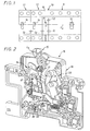
- the adaptation interface 10 is intended to be inserted between, on the one hand, a differential switch 11, and, on the other hand, one or more electrical auxiliaries 12 .
- All these electrical devices are also intended to be arranged in line on the same support, in practice a standardized rail, being successively joined to each other by the main faces of their housings.
- the mechanical connection L1 constitutes for the adaptation interface 10 a mechanical input connection by which it is capable of being actuated by a member of the mechanism of the differential switch 11, constituted, in practice, by the shaft of the support of contacts which this one comprises.
- the mechanical link L2 constitutes for the adaptation interface 10 a mechanical outlet link by which a member of its own mechanism is capable actuate the differential switch 11.
- this mechanical connection L3 is a bidirectional mechanical connection by which, on the one hand, the adaptation interface 10 is able to actuate the electrical auxiliary 12 immediately adjacent in response to a triggering of the differential switch 11, and, step by step, the other electrical auxiliaries 12, and by which, on the other hand, it is also capable of being actuated by this electrical auxiliary 12 immediately adjacent, in response, possibly, to the triggering of 'a more distant electrical auxiliary 12, for triggering the differential switch 11.
- the adaptation interface 10 itself comprises, on the front, in the embodiment shown, a lever 15, which, in practice, is only there to ensure, at in the manner of a spacer, the continuity of the mechanical link L4, without having, as will appear below, any effect on the operation of this adaptation interface 10.
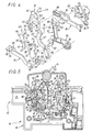
- the adaptation interface 10 comprises, overall, in a housing 16 of which only the base 18 is shown in FIGS. 2 to 9, a lever for input 20, which, pivotally mounted on the housing 16 at a first fixed point Al thereof, is capable of being actuated by the differential switch 11, an input and output lever 21, which, pivotally mounted on the housing 16 at a second fixed point A2 thereof spaced from the first, is capable of being actuated by the electrical auxiliary 12 immediately adjacent or of actuating the latter, an intermediate lever 22, which, coupled to the lever d the inlet 20 by a buttonhole assembly detailed later, is articulated in scissors to the inlet and outlet lever 21 so as to entrain the latter with it when it is itself driven by the inlet lever 20, and an output lever 24 which, pivotally mounted on the housing 16 at a third fixed point A3 thereof, is capable of triggering the differential switch 11 in response to an action by the electrical auxiliary 12 in question on the input and output lever 21, and which , to
- fixed point of the housing 16 is meant here, for the sake of convenience, an area of this housing 16 by which there is a rotation about an axis whose trace on the bottom 25 of the base 18 of this housing 16 is a single point, as shown schematically in Figure 5.
- the input lever 20 is in the general form of a flange.
- this finger 28 which has flats, is intended to come into rotation with the support shaft. of contacts included in the differential switch 11.
- the input lever 20 On either side of the hub 26, the input lever 20 generally forms two arms 30, 31.
- the arm 30 has a notch 32, which is elongated along its length, in the manner of a slot, and with which is engaged a lug 34 provided for this purpose on the intermediate lever 22, the assembly constituting the buttonhole assembly intervening between the input lever 20 and this intermediate lever 22.
- the other arm 31 of the input lever 20 has a general plane which is slightly offset from that of the arm 30, and it has, for its part, protruding, for reasons which will appear below, on the side opposite the hub. 26, a pivot 35, which, in practice, is in alignment with the notch 32.
- the input and output lever 21 also comprises, on either side of a median zone on which protrudes, on the face facing the bottom 25 of the base 18 of the housing 16, a pivot 36, two arms 38, 39.
- the arm 38 includes a lumen 40, which is extended by means of a sleeve 41 projecting from the same face as the pivot 36, and by means of which a finger, not shown, can intervene, in practice with play , belonging to the mechanism of the electrical auxiliary 12 immediately adjacent, the assembly constituting the corresponding mechanical connection L3.
- the lumen 40 has a rectangular outline.
- the general plane of the arm 39 is offset from that of the arm 38.
- the arm 39 of the input and output lever 21 also has an ear 43, which is extended by means of a socket 44, and by which it is engaged in rotation on an axis 45 present for this purpose projecting from the bottom 25 of the base 18 of the housing 16, along the fixed point A2 thereof.
- the intermediate lever 22 is rotatably engaged on the pivot 36 of the inlet and outlet lever 21, and, on either side of this ear 46, it also has , two arms 47, 48.
- the arm 47 is generally curved, in order to circumvent the sleeve 41 of the inlet and outlet lever 21.
- the general plane of the arm 48 of the intermediate lever 22 is offset with respect to that of the arm 47, but in the opposite direction to the offset which corollarily exists between the two arms 38, 39 of the input and output lever 21.
- the intermediate lever 22 and the input and output lever 21 thus intersect each other on either side of their median articulation zone, in the manner of the two blades of a pair of scissors .
- the arm 48 of the intermediate lever 22 therefore extends beyond the arm 39 of the input and output lever 21 relative to the input lever 20, and therefore, relative to the bottom 25 of the base 18 of the housing 16.
- this arm 48 carries, projecting at its end, on its opposite face, a pivot 50.
- the output lever 24 also has, in its central region, an ear 52, by which it is engaged in rotation on an axis 53 provided for this purpose projecting from the bottom 25 of the base 18 of the housing 16, according to the third fixed point A3 thereof.
- this ear 52 On either side of this ear 52, it comprises, overall, two arms 54, 55.
- the arm 54 projects, in the direction of the bottom 25 of the base 18 of the housing 16, a finger 56 which, by means of a light 57 from this bottom 25, protrudes out of this base 18, in order to participate in the constitution of the mechanical link L2.
- the arm 55 has, itself, projecting, on the same face as that on which protrudes this finger 56, a finger 58.
- the output lever 24 is associated, on the one hand, with elastic means 59, which permanently urge this output lever 24 in the direction for which it is capable of triggering the differential switch 11, and, on the other hand, a retaining lever 60, with which it is capable of being engaged by hooking means 61, and by means of which it is under the control of the intermediate lever 22.
- the retaining lever 60 is pivotally mounted on the housing 16 at a fourth fixed point A4 thereof.
- the retaining lever 60 On either side of this ear 62, which is extended by means of a socket 65, the retaining lever 60 has two arms 66, 67.
- the hooking means 61 intervene between the arm 66 and a spout 69 which laterally projecting for this purpose from the arm 54 corresponding to the output lever 24.
- these hooking means 61 comprise, on the arm 66 of the retaining lever 60, a hook 70, and, on the spout 69 of the outlet lever 24, a hook 71.
- the retaining lever 60 is permanently urged to bear, by its arm 67, against a stop 73 provided for it on a trigger puller 75 which, by an ear 76 provided for this purpose at its opposite end , is articulated to the intermediate lever 22 in favor of the pivot 50 which the arm 48 projecting from the latter comprises.
- the elastic means 72 associated with the retaining lever 60 are constituted by a torsion spring, which, by its median torsion part 78, is engaged on a pin 79 provided for this purpose projecting from the pull tab 75, and one branch 80 of which bears on the arm 66 of the retaining lever 60 while the other branch 81 bears on a finger 82 provided for this purpose projecting from the trigger puller 75 parallel to the pin 79.
- the trigger zipper 75 carries, laterally, projecting, back to back with the pin 79, a lug 83 by which it is engaged with a bowl 84 which, elongated in the buttonhole, projects itself on the bottom 25 of the base 18 of the housing 16.
- a reset button 85 with which the output lever 24 is engaged by a game assembly.
- this reset button 85 extends substantially parallel to the trigger pull 75.
- the reset button 85 At one of its ends, which is offset from its general plane in the manner of the arm 31 of the input lever 20 but in the opposite direction relative to the latter, the reset button 85 includes an ear 86, by which it is rotatably engaged on the pivot 35 of this arm 31.
- this reset button 85 includes a light 88, which is elongated, in the manner of a buttonhole, in its own direction of elongation, and by which it is engaged with the finger 58 of the output lever 24, the assembly constituting the corresponding clearance assembly.
- a switching means 89 which, in practice, and as described in European patent application No 0 650 178, is formed by a blade 90 pivotally mounted between two fixed contacts 91.
- This switching means 89 is under the control of a tilting lever 92 which, pivotally mounted on the housing 16 around the second fixed point A2 thereof, is engaged, by a fork 93, with the blade 90, and which is subjected to elastic means, explained below, which permanently urge it to bear against the input lever 20.
- this tilting lever 92 has, generally at right angles to one another, two arms 94, 95.
- the arm 94 carries the fork 93, and, at the other of its ends, it has an ear 96 by which it is engaged in rotation on a hub 97 provided for this purpose projecting from the bottom 25 of the base 18 of the housing 16, coaxially around the axis 45, this hub 97 falling, like this axis 45, from the second fixed point A2 of this housing 16.
- the arm 95 At its end opposite the arm 94, the arm 95 has a boss 98, by which it is adapted to bear on the input lever 20, and, more precisely, on the edge of the arm 30 thereof having the notch 32.
- the elastic means 59 associated with the outlet lever 24 bear on the tilting lever 92.
- these elastic means 59 are constituted by a torsion spring which, by its median torsion part 99, is engaged on a pin 100 provided for this purpose projecting from the bottom 25 of the base 18 of the housing 16, and which, by a branch 101, bears on the arm 54 of the outlet lever 24, by means of a finger 102 provided for this purpose laterally projecting thereon parallel to finger 56, however, by its other branch 104, it bears on the arm 95 of the trigger lever 92, thanks to a boss 105 also provided laterally projecting therefrom.
- the input lever 20 comprises, for the support of the tilting lever 92, a cam surface 106, which belongs to its arm 30, being formed by the edge of the latter, and a portion 107 of which, at least, extends circularly, being centered on the hub 26, and therefore on the first fixed point Al of the housing 16.
- the cam surface 106 has two portions, namely, in addition to the circular portion 107, a rectilinear portion 108, which extends substantially radially with respect to the circular portion 107.
- the boss 98 of the tilting lever 92 comprises, in dihedral, two flaps 109, 110.
- the pan 109 extends obliquely to the direction of elongation of the arm 95 of this tilting lever 92, while the pan 110 is straight, insofar as it extends substantially parallel to this direction elongation.
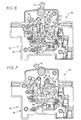
- the input lever 20 bears against a stop 113 provided for this purpose on the housing 16, the tilting lever 92 carries by the oblique face 109 of its boss 98 against the straight portion 108 of the cam surface 106 of this input lever 20, the switching means 89 is in a first state, for which its blade 90 bears for example on the fixed contact 91 closest to the lever 15, as shown, the pivot 36 input lever and outlet 21 is substantially aligned with the first and second fixed points A1, A2 of the housing 16, between them, the pair of scissors formed by this inlet and outlet lever 21 and the intermediate lever 22 is closed, the output lever 24 is engaged with the retaining lever 60, with, however, a slight clearance between its hook 71 and the hook 70 thereof, and, under the stress of the elastic means 59, the finger 58 of this lever outlet 24 abuts against that of the ends of the lumen 88 of the reset button 85 which is closest to the input lever 20 to which it is coupled.
- the engagement that is to say the passage into the closed state of the differential switch 11, implies an action on the lever 13 thereof.
- the input lever 20 carries with it the intermediate lever 22, which, by the pivot 36, in turn drives the lever input and output 21, so that the pair of scissors that jointly form this intermediate lever 22 and this input and output lever 21 remains closed and that the assembly rotates in one piece around the second fixed point A2 of the housing 16, in practice counterclockwise, as shown schematically by an arrow F2 in FIG. 6.
- the input lever 20 also drives, in the anti-clockwise direction, the tilting lever 92, according to arrow F2 in FIG. 6.
- the input lever 20 also drives, by the pivot 35, counterclockwise, and as shown diagrammatically by an arrow F3 in FIG. 6, the reset button 85, the output lever 24 , thus released, rotates counterclockwise, under the stress of the elastic means 59, around the third fixed point A3 of the housing 16, as shown schematically by an arrow F4 in FIG. 6, which leads its hook 71 to engaging the hook 70 of the retaining lever 60, after absorption of the initial guard between them.
- the retaining lever 60 remains, for its part, in abutment against the stop 73 of the trigger zipper 75, which itself remains stationary, since the pivot 50 on which it is articulated is in line with the second fixed point A2 of the housing 16 and thus remains fixed in the pivoting movement of the intermediate lever 22 which carries it.
- the input lever 20 can continue to rotate, without interfering with the position of the tilt lever 92.
- the handle 15 of the adaptation interface 10 duly driven by the handle 13 of the differential switch 11, has rotated, counterclockwise, around its axis of rotation, as shown in Figures 5, 6 and 7.
- the electrical auxiliaries 12 are themselves engaged, the input and output lever 21, which follows the corresponding engagement movement, remaining engaged, with play, with the member concerned. electrical auxiliary 12 immediately adjacent, following the mechanical connection L3.
- the input and output lever 21 causes, by the mechanical connection L3, the triggering of the electrical auxiliary 12 immediately adjacent, and, consequently, that of the following electrical auxiliary 12, and so on. continuation, step by step, from one electrical auxiliary 12 to another, when more than two electrical auxiliaries 12 are present.
- the trigger zipper 75 in turn causes the pivoting lever, counterclockwise, of the retaining lever 60, around the fourth fixed point A4 of the housing 16, as shown diagrammatically by an arrow F9 in FIG. 8, which releases the output lever 24.
- the outlet lever 24 rotates, counterclockwise, around the third fixed point A3 of the housing 16, as shown schematically by an arrow F10 in FIG. 8, which, by its finger 56 and the mechanical connection L2 to which it belongs, causes the differential switch 11 to trip, by supplying the latter, by the contribution thus made of elastic means 59, all the energy necessary for this triggering.
- the differential switch 11 ensures, by itself, when it is triggered, the resetting of the adaptation interface 10 according to the invention.
- the tilting lever 92 remains stationary at first, the time that, by its circular portion 107, the cam surface 106 of the input lever 20 remains in contact with the right side 110 of its boss 98, which advantageously ensures temporary maintenance of the blade 90 of the switching means 89 in the position which is hers for the closing state of the differential switch 11.
- the tilting lever 92 ensures the return of the blade 90 of the switching means 89 to its initial position, as shown.
- the tilting lever 92 then intervenes under the sole request of the elastic means 59, which relax, without taking any energy, in the differential switch 11.
Landscapes
- Mechanisms For Operating Contacts (AREA)
- Dc Digital Transmission (AREA)
- Oscillators With Electromechanical Resonators (AREA)
- Mechanical Control Devices (AREA)
- Coupling Device And Connection With Printed Circuit (AREA)
Applications Claiming Priority (2)
| Application Number | Priority Date | Filing Date | Title |
|---|---|---|---|
| FR9514207 | 1995-12-01 | ||
| FR9514207A FR2741992B1 (fr) | 1995-12-01 | 1995-12-01 | Interface d'adaptation a inserer entre un interrupteur differentiel et un auxiliaire electrique |
Publications (2)
| Publication Number | Publication Date |
|---|---|
| EP0777251A1 true EP0777251A1 (de) | 1997-06-04 |
| EP0777251B1 EP0777251B1 (de) | 2001-09-12 |
Family
ID=9485049
Family Applications (1)
| Application Number | Title | Priority Date | Filing Date |
|---|---|---|---|
| EP96402575A Expired - Lifetime EP0777251B1 (de) | 1995-12-01 | 1996-11-28 | Schnittstelle zur Anpassung zwischen Differentialschalter und elektrisches Hilfmittel |
Country Status (5)
| Country | Link |
|---|---|
| EP (1) | EP0777251B1 (de) |
| AT (1) | ATE205633T1 (de) |
| DE (1) | DE69615128T2 (de) |
| ES (1) | ES2160218T3 (de) |
| FR (1) | FR2741992B1 (de) |
Citations (1)
| Publication number | Priority date | Publication date | Assignee | Title |
|---|---|---|---|---|
| EP0650178A1 (de) | 1993-10-22 | 1995-04-26 | Legrand | Schnittstelle zur Anpassung für mehrpoliger Differentialschalter |
-
1995
- 1995-12-01 FR FR9514207A patent/FR2741992B1/fr not_active Expired - Fee Related
-
1996
- 1996-11-28 ES ES96402575T patent/ES2160218T3/es not_active Expired - Lifetime
- 1996-11-28 DE DE69615128T patent/DE69615128T2/de not_active Expired - Fee Related
- 1996-11-28 AT AT96402575T patent/ATE205633T1/de not_active IP Right Cessation
- 1996-11-28 EP EP96402575A patent/EP0777251B1/de not_active Expired - Lifetime
Patent Citations (1)
| Publication number | Priority date | Publication date | Assignee | Title |
|---|---|---|---|---|
| EP0650178A1 (de) | 1993-10-22 | 1995-04-26 | Legrand | Schnittstelle zur Anpassung für mehrpoliger Differentialschalter |
Also Published As
| Publication number | Publication date |
|---|---|
| DE69615128T2 (de) | 2002-01-31 |
| ATE205633T1 (de) | 2001-09-15 |
| FR2741992A1 (fr) | 1997-06-06 |
| DE69615128D1 (de) | 2001-10-18 |
| EP0777251B1 (de) | 2001-09-12 |
| FR2741992B1 (fr) | 1998-02-13 |
| ES2160218T3 (es) | 2001-11-01 |
Similar Documents
| Publication | Publication Date | Title |
|---|---|---|
| FR2548574A1 (fr) | Dispositif de freinage pour chaine | |
| FR2863403A1 (fr) | Dispositif de signalisation du declenchement d'un appareil de protection electrique et appareil de protection electrique le comportant | |
| EP0696041B1 (de) | Schutzschalter | |
| FR2900498A1 (fr) | Disjoncteur de circuit | |
| EP0143682B1 (de) | Selbstschalter, insbesondere Fehler- und Überstromschalter | |
| CA2002308C (fr) | Mecanisme a serrure pour contacteur-limiteur | |
| WO2001069635A1 (fr) | Commande electrique de disjoncteur | |
| EP0669633B1 (de) | Schutzschaltgerät | |
| EP0802547B1 (de) | Sicherheitsvorrichtung für ein elektrisches bewegliches Bauelement und Grill mit einer derartigen Vorrichtung | |
| EP2717284B1 (de) | Bedienungsvorrichtung eines elektrischen Schutzschaltgeräts, und diese umfassendes elektrisches Schutzschaltgerät | |
| EP0777251B1 (de) | Schnittstelle zur Anpassung zwischen Differentialschalter und elektrisches Hilfmittel | |
| EP1274109B1 (de) | Betätigungsmechanismus für einen Lastschalter | |
| EP0685867B1 (de) | Differential-Auslösevorrichtung | |
| EP0604330B1 (de) | Modularer Schutzschalter in Verbindung mit einer Fernbedienungseinheit | |
| FR2628261A1 (fr) | Disjoncteur a mecanisme a franchissement de point mort | |
| EP0461027B1 (de) | Differential Auslösevorrichtung | |
| EP3657522B1 (de) | Betätigungsmechanismus zum öffnen und schliessen einer stromunterbrechungsvorrichtung für einen elektrichen schalter | |
| WO2000045408A1 (fr) | Mecanisme de commande d'un disjoncteur electrique | |
| EP0650178A1 (de) | Schnittstelle zur Anpassung für mehrpoliger Differentialschalter | |
| FR2908234A1 (fr) | Dispositif d'actionnement deporte pour un disjoncteur incluant un dispositif d'assistance au declenchement | |
| WO1984002802A1 (fr) | Interrupteur a fermeture et ouverture commandees et a ouverture automatique en cas de surcharge de courant | |
| EP0218497B1 (de) | Schutzschalter mit federnder Lasche | |
| FR2751121A1 (fr) | Interrupteur comportant deux balais conducteurs, tel que permutateur ou interrupteur pour volet roulant | |
| FR2796488A1 (fr) | Dispositif pour activer et desactiver des appareils de commutation agences sous forme de bloc | |
| EP0327460A1 (de) | Elektrischer Schalter mit automatischer Ausschaltung, insbesondere Differentialschutz |
Legal Events
| Date | Code | Title | Description |
|---|---|---|---|
| PUAI | Public reference made under article 153(3) epc to a published international application that has entered the european phase |
Free format text: ORIGINAL CODE: 0009012 |
|
| AK | Designated contracting states |
Kind code of ref document: A1 Designated state(s): AT BE DE ES GB IT |
|
| 17P | Request for examination filed |
Effective date: 19970630 |
|
| GRAG | Despatch of communication of intention to grant |
Free format text: ORIGINAL CODE: EPIDOS AGRA |
|
| GRAG | Despatch of communication of intention to grant |
Free format text: ORIGINAL CODE: EPIDOS AGRA |
|
| GRAH | Despatch of communication of intention to grant a patent |
Free format text: ORIGINAL CODE: EPIDOS IGRA |
|
| 17Q | First examination report despatched |
Effective date: 20010207 |
|
| GRAH | Despatch of communication of intention to grant a patent |
Free format text: ORIGINAL CODE: EPIDOS IGRA |
|
| GRAA | (expected) grant |
Free format text: ORIGINAL CODE: 0009210 |
|
| AK | Designated contracting states |
Kind code of ref document: B1 Designated state(s): AT BE DE ES GB IT |
|
| REF | Corresponds to: |
Ref document number: 205633 Country of ref document: AT Date of ref document: 20010915 Kind code of ref document: T |
|
| REF | Corresponds to: |
Ref document number: 69615128 Country of ref document: DE Date of ref document: 20011018 |
|
| REG | Reference to a national code |
Ref country code: ES Ref legal event code: FG2A Ref document number: 2160218 Country of ref document: ES Kind code of ref document: T3 |
|
| GBT | Gb: translation of ep patent filed (gb section 77(6)(a)/1977) |
Effective date: 20011023 |
|
| REG | Reference to a national code |
Ref country code: GB Ref legal event code: IF02 |
|
| PLBE | No opposition filed within time limit |
Free format text: ORIGINAL CODE: 0009261 |
|
| STAA | Information on the status of an ep patent application or granted ep patent |
Free format text: STATUS: NO OPPOSITION FILED WITHIN TIME LIMIT |
|
| 26N | No opposition filed | ||
| PGFP | Annual fee paid to national office [announced via postgrant information from national office to epo] |
Ref country code: AT Payment date: 20051018 Year of fee payment: 10 |
|
| PGFP | Annual fee paid to national office [announced via postgrant information from national office to epo] |
Ref country code: GB Payment date: 20051115 Year of fee payment: 10 |
|
| PGFP | Annual fee paid to national office [announced via postgrant information from national office to epo] |
Ref country code: ES Payment date: 20051116 Year of fee payment: 10 |
|
| PGFP | Annual fee paid to national office [announced via postgrant information from national office to epo] |
Ref country code: BE Payment date: 20051208 Year of fee payment: 10 |
|
| PGFP | Annual fee paid to national office [announced via postgrant information from national office to epo] |
Ref country code: DE Payment date: 20061108 Year of fee payment: 11 |
|
| PG25 | Lapsed in a contracting state [announced via postgrant information from national office to epo] |
Ref country code: AT Free format text: LAPSE BECAUSE OF NON-PAYMENT OF DUE FEES Effective date: 20061128 |
|
| PG25 | Lapsed in a contracting state [announced via postgrant information from national office to epo] |
Ref country code: BE Free format text: LAPSE BECAUSE OF NON-PAYMENT OF DUE FEES Effective date: 20061130 |
|
| PGFP | Annual fee paid to national office [announced via postgrant information from national office to epo] |
Ref country code: IT Payment date: 20061130 Year of fee payment: 11 |
|
| GBPC | Gb: european patent ceased through non-payment of renewal fee |
Effective date: 20061128 |
|
| PG25 | Lapsed in a contracting state [announced via postgrant information from national office to epo] |
Ref country code: GB Free format text: LAPSE BECAUSE OF NON-PAYMENT OF DUE FEES Effective date: 20061128 |
|
| BERE | Be: lapsed |
Owner name: *LEGRAND SNC Effective date: 20061130 Owner name: *LEGRAND Effective date: 20061130 |
|
| REG | Reference to a national code |
Ref country code: ES Ref legal event code: FD2A Effective date: 20061129 |
|
| PG25 | Lapsed in a contracting state [announced via postgrant information from national office to epo] |
Ref country code: ES Free format text: LAPSE BECAUSE OF NON-PAYMENT OF DUE FEES Effective date: 20061129 |
|
| PG25 | Lapsed in a contracting state [announced via postgrant information from national office to epo] |
Ref country code: DE Free format text: LAPSE BECAUSE OF NON-PAYMENT OF DUE FEES Effective date: 20080603 |
|
| PG25 | Lapsed in a contracting state [announced via postgrant information from national office to epo] |
Ref country code: IT Free format text: LAPSE BECAUSE OF NON-PAYMENT OF DUE FEES Effective date: 20071128 |