EP0777302A1 - Dispositif de connexion d'embout de fil - Google Patents
Dispositif de connexion d'embout de fil Download PDFInfo
- Publication number
- EP0777302A1 EP0777302A1 EP96119196A EP96119196A EP0777302A1 EP 0777302 A1 EP0777302 A1 EP 0777302A1 EP 96119196 A EP96119196 A EP 96119196A EP 96119196 A EP96119196 A EP 96119196A EP 0777302 A1 EP0777302 A1 EP 0777302A1
- Authority
- EP
- European Patent Office
- Prior art keywords
- terminal fitting
- terminal
- wire
- guide portion
- end connection
- Prior art date
- Legal status (The legal status is an assumption and is not a legal conclusion. Google has not performed a legal analysis and makes no representation as to the accuracy of the status listed.)
- Granted
Links
Images







Classifications
-
- H—ELECTRICITY
- H01—ELECTRIC ELEMENTS
- H01R—ELECTRICALLY-CONDUCTIVE CONNECTIONS; STRUCTURAL ASSOCIATIONS OF A PLURALITY OF MUTUALLY-INSULATED ELECTRICAL CONNECTING ELEMENTS; COUPLING DEVICES; CURRENT COLLECTORS
- H01R24/00—Two-part coupling devices, or either of their cooperating parts, characterised by their overall structure
- H01R24/20—Coupling parts carrying sockets, clips or analogous contacts and secured only to wire or cable
-
- H—ELECTRICITY
- H01—ELECTRIC ELEMENTS
- H01R—ELECTRICALLY-CONDUCTIVE CONNECTIONS; STRUCTURAL ASSOCIATIONS OF A PLURALITY OF MUTUALLY-INSULATED ELECTRICAL CONNECTING ELEMENTS; COUPLING DEVICES; CURRENT COLLECTORS
- H01R13/00—Details of coupling devices of the kinds covered by groups H01R12/70 or H01R24/00 - H01R33/00
- H01R13/62—Means for facilitating engagement or disengagement of coupling parts or for holding them in engagement
- H01R13/629—Additional means for facilitating engagement or disengagement of coupling parts, e.g. aligning or guiding means, levers, gas pressure electrical locking indicators, manufacturing tolerances
- H01R13/631—Additional means for facilitating engagement or disengagement of coupling parts, e.g. aligning or guiding means, levers, gas pressure electrical locking indicators, manufacturing tolerances for engagement only
-
- H—ELECTRICITY
- H01—ELECTRIC ELEMENTS
- H01R—ELECTRICALLY-CONDUCTIVE CONNECTIONS; STRUCTURAL ASSOCIATIONS OF A PLURALITY OF MUTUALLY-INSULATED ELECTRICAL CONNECTING ELEMENTS; COUPLING DEVICES; CURRENT COLLECTORS
- H01R11/00—Individual connecting elements providing two or more spaced connecting locations for conductive members which are, or may be, thereby interconnected, e.g. end pieces for wires or cables supported by the wire or cable and having means for facilitating electrical connection to some other wire, terminal, or conductive member, blocks of binding posts
- H01R11/11—End pieces or tapping pieces for wires, supported by the wire and for facilitating electrical connection to some other wire, terminal or conductive member
-
- H—ELECTRICITY
- H01—ELECTRIC ELEMENTS
- H01R—ELECTRICALLY-CONDUCTIVE CONNECTIONS; STRUCTURAL ASSOCIATIONS OF A PLURALITY OF MUTUALLY-INSULATED ELECTRICAL CONNECTING ELEMENTS; COUPLING DEVICES; CURRENT COLLECTORS
- H01R13/00—Details of coupling devices of the kinds covered by groups H01R12/70 or H01R24/00 - H01R33/00
- H01R13/46—Bases; Cases
- H01R13/52—Dustproof, splashproof, drip-proof, waterproof, or flameproof cases
- H01R13/5219—Sealing means between coupling parts, e.g. interfacial seal
-
- H—ELECTRICITY
- H01—ELECTRIC ELEMENTS
- H01R—ELECTRICALLY-CONDUCTIVE CONNECTIONS; STRUCTURAL ASSOCIATIONS OF A PLURALITY OF MUTUALLY-INSULATED ELECTRICAL CONNECTING ELEMENTS; COUPLING DEVICES; CURRENT COLLECTORS
- H01R13/00—Details of coupling devices of the kinds covered by groups H01R12/70 or H01R24/00 - H01R33/00
- H01R13/46—Bases; Cases
- H01R13/53—Bases or cases for heavy duty; Bases or cases for high voltage with means for preventing corona or arcing
-
- H—ELECTRICITY
- H01—ELECTRIC ELEMENTS
- H01R—ELECTRICALLY-CONDUCTIVE CONNECTIONS; STRUCTURAL ASSOCIATIONS OF A PLURALITY OF MUTUALLY-INSULATED ELECTRICAL CONNECTING ELEMENTS; COUPLING DEVICES; CURRENT COLLECTORS
- H01R2101/00—One pole
-
- H—ELECTRICITY
- H01—ELECTRIC ELEMENTS
- H01R—ELECTRICALLY-CONDUCTIVE CONNECTIONS; STRUCTURAL ASSOCIATIONS OF A PLURALITY OF MUTUALLY-INSULATED ELECTRICAL CONNECTING ELEMENTS; COUPLING DEVICES; CURRENT COLLECTORS
- H01R4/00—Electrically-conductive connections between two or more conductive members in direct contact, i.e. touching one another; Means for effecting or maintaining such contact; Electrically-conductive connections having two or more spaced connecting locations for conductors and using contact members penetrating insulation
- H01R4/10—Electrically-conductive connections between two or more conductive members in direct contact, i.e. touching one another; Means for effecting or maintaining such contact; Electrically-conductive connections having two or more spaced connecting locations for conductors and using contact members penetrating insulation effected solely by twisting, wrapping, bending, crimping, or other permanent deformation
- H01R4/18—Electrically-conductive connections between two or more conductive members in direct contact, i.e. touching one another; Means for effecting or maintaining such contact; Electrically-conductive connections having two or more spaced connecting locations for conductors and using contact members penetrating insulation effected solely by twisting, wrapping, bending, crimping, or other permanent deformation by crimping
- H01R4/183—Electrically-conductive connections between two or more conductive members in direct contact, i.e. touching one another; Means for effecting or maintaining such contact; Electrically-conductive connections having two or more spaced connecting locations for conductors and using contact members penetrating insulation effected solely by twisting, wrapping, bending, crimping, or other permanent deformation by crimping for cylindrical elongated bodies, e.g. cables having circular cross-section
Definitions
- the internal combustion engine of a vehicle is provided with a distributor with which a spark coil or the like is connected via a high voltage resistive wire.
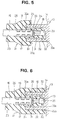
- the seal member is formed with the guide portion.
- the guide portion is formed into a preferably hollow substantially cylindrical shape.
- one or more projections are formed on the guide portion, the two or more projections being preferably equally spaced in the circumferential direction.
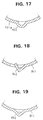
- a guide portion 51 of the seventh embodiment is formed with lips 52.
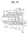
- the rear part of the through hole 123 has a diameter slightly smaller than the that of the wire 116, and the front part thereof is formed to have a slightly larger diameter (slightly smaller than the barrel portion 117) than that of the rear part, thereby forming a retaining portion 126.
- the barrel portion 117 of the female terminal fitting 112 connected with the wire 116 is fitted into the retaining portion 126 through the through hole 123, with the result that the female terminal fitting 112 is retained with the connection portion 118 projecting into the sealing tubular portion 122.
- An opening edge 122a of the sealing tubular portion 122 is tapered so as to make it easier to fit the sealing tubular portion 122 to the outer surface of the receptacle 115.
- the female terminal fitting 112 is inserted into the receptacle 115 while the seal member 121 is fitted on the receptacle 115.
- the guide surface 124a of the guide portion 124 comes into contact with the opening edge 115a of the receptacle 115. Accordingly, while being pressed into the receptacle 115, the female terminal fitting 112 is guide to its proper insertion position, and consequently connected with the male terminal fitting 111.
- the terminal fittings 111, 112 are securely connected, and the opening of the receptacle 115 is sealed watertight (see FIG. 13).
Landscapes
- Connector Housings Or Holding Contact Members (AREA)
Applications Claiming Priority (6)
| Application Number | Priority Date | Filing Date | Title |
|---|---|---|---|
| JP338217/95 | 1995-12-01 | ||
| JP07338218A JP3111876B2 (ja) | 1995-12-01 | 1995-12-01 | 電線の端末接続構造 |
| JP33821895 | 1995-12-01 | ||
| JP33821795A JPH09161887A (ja) | 1995-12-01 | 1995-12-01 | 電線の端末接続構造 |
| JP33821795 | 1995-12-01 | ||
| JP338218/95 | 1995-12-01 |
Publications (2)
| Publication Number | Publication Date |
|---|---|
| EP0777302A1 true EP0777302A1 (fr) | 1997-06-04 |
| EP0777302B1 EP0777302B1 (fr) | 2002-07-31 |
Family
ID=26576042
Family Applications (1)
| Application Number | Title | Priority Date | Filing Date |
|---|---|---|---|
| EP19960119196 Expired - Lifetime EP0777302B1 (fr) | 1995-12-01 | 1996-11-29 | Dispositif de connexion d'embout de fil |
Country Status (3)
| Country | Link |
|---|---|
| EP (1) | EP0777302B1 (fr) |
| CN (1) | CN1057876C (fr) |
| DE (1) | DE69622668T2 (fr) |
Cited By (4)
| Publication number | Priority date | Publication date | Assignee | Title |
|---|---|---|---|---|
| EP1024558A3 (fr) * | 1999-01-28 | 2002-01-30 | Sumitomo Wiring Systems, Ltd. | Dispositif d'accouplement d'un câble à haute tension |
| GB2393045A (en) * | 2002-07-25 | 2004-03-17 | Yazaki Corp | Connector structure |
| US8927863B2 (en) | 2010-08-06 | 2015-01-06 | Sumitomo Wiring Systems, Ltd. | Anti-corrosion structure for wire connecting portion |
| WO2018050980A1 (fr) | 2016-09-13 | 2018-03-22 | PELLENC (Société Anonyme) | Dispositif de connexion électrique manuelle à engagement guidé |
Families Citing this family (4)
| Publication number | Priority date | Publication date | Assignee | Title |
|---|---|---|---|---|
| JP5973865B2 (ja) * | 2012-10-10 | 2016-08-23 | 矢崎総業株式会社 | 触指防止コネクタ |
| CN108461984A (zh) * | 2017-02-17 | 2018-08-28 | 神讯电脑(昆山)有限公司 | 连接器装置 |
| JP6981388B2 (ja) * | 2018-10-04 | 2021-12-15 | 株式会社オートネットワーク技術研究所 | 雄型コネクタおよびコネクタ装置 |
| CN112397969B (zh) * | 2020-01-03 | 2022-03-25 | 深圳市胜霖机电设备有限公司 | 一种配电产品接线的控制方法 |
Citations (4)
| Publication number | Priority date | Publication date | Assignee | Title |
|---|---|---|---|---|
| US3335392A (en) * | 1965-07-19 | 1967-08-08 | Essex Wire Corp | Terminal construction |
| US5026294A (en) * | 1989-03-03 | 1991-06-25 | Nissan Motor Co., Ltd. | Ignition plug socket structure |
| EP0565465A1 (fr) * | 1992-04-07 | 1993-10-13 | Société à Responsabilité Limitée L'ELECTRICFIL INDUSTRIE | Cosse femelle de connexion électrique pour borne de raccordement |
| EP0602698A1 (fr) * | 1992-12-14 | 1994-06-22 | General Motors Corporation | Assemblage étanche de câble |
-
1996
- 1996-11-29 DE DE1996622668 patent/DE69622668T2/de not_active Expired - Fee Related
- 1996-11-29 EP EP19960119196 patent/EP0777302B1/fr not_active Expired - Lifetime
- 1996-11-30 CN CN 96117387 patent/CN1057876C/zh not_active Expired - Fee Related
Patent Citations (4)
| Publication number | Priority date | Publication date | Assignee | Title |
|---|---|---|---|---|
| US3335392A (en) * | 1965-07-19 | 1967-08-08 | Essex Wire Corp | Terminal construction |
| US5026294A (en) * | 1989-03-03 | 1991-06-25 | Nissan Motor Co., Ltd. | Ignition plug socket structure |
| EP0565465A1 (fr) * | 1992-04-07 | 1993-10-13 | Société à Responsabilité Limitée L'ELECTRICFIL INDUSTRIE | Cosse femelle de connexion électrique pour borne de raccordement |
| EP0602698A1 (fr) * | 1992-12-14 | 1994-06-22 | General Motors Corporation | Assemblage étanche de câble |
Cited By (5)
| Publication number | Priority date | Publication date | Assignee | Title |
|---|---|---|---|---|
| EP1024558A3 (fr) * | 1999-01-28 | 2002-01-30 | Sumitomo Wiring Systems, Ltd. | Dispositif d'accouplement d'un câble à haute tension |
| GB2393045A (en) * | 2002-07-25 | 2004-03-17 | Yazaki Corp | Connector structure |
| GB2393045B (en) * | 2002-07-25 | 2004-11-17 | Yazaki Corp | Connector structure |
| US8927863B2 (en) | 2010-08-06 | 2015-01-06 | Sumitomo Wiring Systems, Ltd. | Anti-corrosion structure for wire connecting portion |
| WO2018050980A1 (fr) | 2016-09-13 | 2018-03-22 | PELLENC (Société Anonyme) | Dispositif de connexion électrique manuelle à engagement guidé |
Also Published As
| Publication number | Publication date |
|---|---|
| DE69622668T2 (de) | 2003-03-13 |
| DE69622668D1 (de) | 2002-09-05 |
| CN1057876C (zh) | 2000-10-25 |
| CN1158506A (zh) | 1997-09-03 |
| EP0777302B1 (fr) | 2002-07-31 |
Similar Documents
| Publication | Publication Date | Title |
|---|---|---|
| EP2166624B1 (fr) | Prise élastique, connecteur étanche et son procédé d'assemblage | |
| EP1583183B1 (fr) | Connecteur étanche et sa méthode d'assemblage | |
| EP0666616B1 (fr) | Broche de contact mâle | |
| EP0646991B1 (fr) | Serre-câble pour connecteur étanché à l'eau | |
| EP0630073A2 (fr) | Bouchon en caoutchouc pour connecteur étanche | |
| EP1432074B1 (fr) | Utilisation d'un bouchon d'étanchéité et connecteur étanche | |
| JP2002343493A (ja) | 端子一体型シール部材 | |
| EP0694994A1 (fr) | Tampon étanche à l'eau pour connecteur étanche à l'eau | |
| JPH07201405A (ja) | コネクタの防水栓 | |
| US5603637A (en) | Waterproof plug structure | |
| EP2073319B1 (fr) | Assemblage de connecteur et sa méthode d'assemblage | |
| EP0777302A1 (fr) | Dispositif de connexion d'embout de fil | |
| US7285013B1 (en) | Terminal fitting, a method of crimping it and a positioning jig | |
| US6764329B2 (en) | Waterproof resilient plug to provide sealing between a wire and a housing | |
| JP2011170996A (ja) | 防水機能付き端子金具及び防水コネクタ | |
| JP4664182B2 (ja) | ガスセンサユニット | |
| US6056562A (en) | Wire end connection construction | |
| JPH09147965A (ja) | 防水コネクタ | |
| EP0637101A1 (fr) | Connecteur étanché et terminal de fil avec tel connecteur | |
| EP0585562A1 (fr) | Connecteur | |
| JP3153758B2 (ja) | 防水栓 | |
| JPH0850956A (ja) | シール用ゴム栓の固定構造 | |
| JP3111876B2 (ja) | 電線の端末接続構造 | |
| JP2000082529A (ja) | 防水コネクタ | |
| JPH10199587A (ja) | 圧着端子 |
Legal Events
| Date | Code | Title | Description |
|---|---|---|---|
| PUAI | Public reference made under article 153(3) epc to a published international application that has entered the european phase |
Free format text: ORIGINAL CODE: 0009012 |
|
| AK | Designated contracting states |
Kind code of ref document: A1 Designated state(s): DE FR GB |
|
| 17P | Request for examination filed |
Effective date: 19970416 |
|
| 17Q | First examination report despatched |
Effective date: 19990222 |
|
| RIC1 | Information provided on ipc code assigned before grant |
Free format text: 7H 01R 13/52 A, 7H 01R 24/00 B, 7H 01R 13/53 B |
|
| RTI1 | Title (correction) |
Free format text: A WIRE END CONNECTION ASSEMBLY |
|
| GRAG | Despatch of communication of intention to grant |
Free format text: ORIGINAL CODE: EPIDOS AGRA |
|
| GRAG | Despatch of communication of intention to grant |
Free format text: ORIGINAL CODE: EPIDOS AGRA |
|
| GRAG | Despatch of communication of intention to grant |
Free format text: ORIGINAL CODE: EPIDOS AGRA |
|
| GRAH | Despatch of communication of intention to grant a patent |
Free format text: ORIGINAL CODE: EPIDOS IGRA |
|
| GRAH | Despatch of communication of intention to grant a patent |
Free format text: ORIGINAL CODE: EPIDOS IGRA |
|
| GRAA | (expected) grant |
Free format text: ORIGINAL CODE: 0009210 |
|
| AK | Designated contracting states |
Kind code of ref document: B1 Designated state(s): DE FR GB |
|
| PG25 | Lapsed in a contracting state [announced via postgrant information from national office to epo] |
Ref country code: FR Free format text: LAPSE BECAUSE OF FAILURE TO SUBMIT A TRANSLATION OF THE DESCRIPTION OR TO PAY THE FEE WITHIN THE PRESCRIBED TIME-LIMIT Effective date: 20020731 |
|
| REG | Reference to a national code |
Ref country code: GB Ref legal event code: FG4D |
|
| REF | Corresponds to: |
Ref document number: 69622668 Country of ref document: DE Date of ref document: 20020905 |
|
| PG25 | Lapsed in a contracting state [announced via postgrant information from national office to epo] |
Ref country code: GB Free format text: LAPSE BECAUSE OF NON-PAYMENT OF DUE FEES Effective date: 20021129 |
|
| PGFP | Annual fee paid to national office [announced via postgrant information from national office to epo] |
Ref country code: DE Payment date: 20030129 Year of fee payment: 7 |
|
| PLBE | No opposition filed within time limit |
Free format text: ORIGINAL CODE: 0009261 |
|
| STAA | Information on the status of an ep patent application or granted ep patent |
Free format text: STATUS: NO OPPOSITION FILED WITHIN TIME LIMIT |
|
| GBPC | Gb: european patent ceased through non-payment of renewal fee | ||
| 26N | No opposition filed |
Effective date: 20030506 |
|
| PG25 | Lapsed in a contracting state [announced via postgrant information from national office to epo] |
Ref country code: DE Free format text: LAPSE BECAUSE OF NON-PAYMENT OF DUE FEES Effective date: 20040602 |