EP0777337A2 - Spreizspektrum-Nachrichtenübertragungsgerät - Google Patents
Spreizspektrum-Nachrichtenübertragungsgerät Download PDFInfo
- Publication number
- EP0777337A2 EP0777337A2 EP96119012A EP96119012A EP0777337A2 EP 0777337 A2 EP0777337 A2 EP 0777337A2 EP 96119012 A EP96119012 A EP 96119012A EP 96119012 A EP96119012 A EP 96119012A EP 0777337 A2 EP0777337 A2 EP 0777337A2
- Authority
- EP
- European Patent Office
- Prior art keywords
- spread
- band
- signal
- wave
- level
- Prior art date
- Legal status (The legal status is an assumption and is not a legal conclusion. Google has not performed a legal analysis and makes no representation as to the accuracy of the status listed.)
- Granted
Links
Images


Classifications
-
- H—ELECTRICITY
- H04—ELECTRIC COMMUNICATION TECHNIQUE
- H04B—TRANSMISSION
- H04B1/00—Details of transmission systems, not covered by a single one of groups H04B3/00 - H04B13/00; Details of transmission systems not characterised by the medium used for transmission
- H04B1/69—Spread spectrum techniques
- H04B1/707—Spread spectrum techniques using direct sequence modulation
- H04B1/7097—Interference-related aspects
- H04B1/71—Interference-related aspects the interference being narrowband interference
Definitions
- the present invention relates to a communication apparatus, in particular to a spread-spectrum communication apparatus for use in mobile communications, wireless LAN, or the like.
- Spread-spectrum techniques expand bandwidth to gain transmission advantages.
- pseudorandom spreading distributes the transmitter's power over a much wider frequency range, with much lower power density. Because the spreading is reversed at a receiver, narrow-band interfering signals are spread before demodulation, and wide-band interfering signals remain wide-band. The interference power density in the reconstructed narrow band remains low, while the higher power density of the desired signal is available to the receiver demodulator. Therefore, interference is reduced.
- BEF band elimination filter
- a suppression filter having saturation characteristics in a frequency region is utilized to suppress signals whose power exceeds a predetermined level which is higher than the power level of the desired spread signal. Thereby, the total power of the interference is decreased relative to that of the desired signal.
- a device such as a diode or an amplifier has a saturating characteristic.
- the power of the desired signal is also decreased because such devices have saturating characteristics in the entire frequency region. In other words, the power of the desired signal is also decreased in a frequency region in which no interference appears.
- Gevargiz, Das, and Milstein developed techniques for adaptive narrow-band interference rejection in a DS spread-spectrum intercept receiver using transform domain signal processing techniques (IEEE Transactions on Communications, Vol. 37, No. 12, December 1989).
- a chirp filter is used as a suppressor.
- the structure of the chirp filter is relatively complex.
- the present invention utilizes a magnetostatic wave device as a suppressing filter.
- a magnetostatic wave device has a variable frequency region in which it has saturating characteristics in accordance with the strength of a magnetic field applied from the exterior.
- the device suppresses an input signal having a power level larger than its saturation level.
- the device presents linear transparency to an input signal whose power level is lower than its saturation level.
- the power of an interference signal can be selectively decreased.
- a magnetostatic wave device Since a magnetostatic wave device has a simpler structure than that of a chirp filter, it is possible to provide an interference suppressor at low cost.
- the present invention provides a spread-spectrum communicating apparatus having an input circuit; a magnetostatic wave device connected to the output of the input circuit; and a despreader connected to the output of the magnetostatic wave device.
- the spread-spectrum communicating apparatus may further include an amplifier for amplifying a spread signal received by the input circuit to a level at which an output level of the magnetostatic wave device is saturated, and forwarding the amplified spread signal to the magnetostatic wave device.
- the spread spectrum communicating apparatus may further include a frequency converter disposed between the magnetostatic wave device and the despreader, for converting the frequency of the signal output from the magnetostatic wave device before the signal is processed in the despreader.
- the present invention reduces a plurality of wide-band or narrow-band interference waves mixed into a spread-spectrum signal to a certain level.
- the energy of the interference waves against that of the spread signal is reduced and the S/N ratio after despreading is improved.
- the level of an interference wave is reduced before despreading and the S/N ratio after the despreading is further improved.
- it is not required to match the frequency of the magnetostatic-wave filter with that of the despreader.
- any magnetostatic-wave filter and any despreader which are usable at various frequencies can be used.
- the magnetostatic-wave filter can be used at high frequencies, at which the filter has superior saturation characteristics.
- Fig. 1 is a circuit block diagram of a spread-spectrum communication apparatus according to a first embodiment of the present invention.
- a receiving antenna 1 and wide-band amplifiers 2 and 3, each having a power gain of 10 dB.
- a band-pass filter (BPF) 4 has a transmission band of at least 370 MHz to 430 MHz, which corresponds to the frequency band of a spread-spectrum signal.
- a threshold filter circuit 5 has a frequency band width covering the spectrum-signal band width and reduces interference waves having a certain level or more. It includes an AGC amplifier 6 and a magnetostatic-wave filter 7.
- the magnetostatic-wave filter 7 is saturated at an input level of -20 dB at each frequency and hence removes input power existing at more than that level, as shown in Fig. 3.
- a signal sustains a loss of -10 dB when it passes through the magnetostatic-wave filter.
- the AGC amplifier 6 connected in series before the magnetostatic-wave filter 7 amplifies (a gain of 10 dB in this case) the level of a signal until the output of the magnetostatic-wave filter 7 is saturated.
- a band-pass filter (BPF) 8 functionally operates in the same way as the band-pass filter (BPF) 4.
- a despreader 9 is made up of a matched filter, for example, and corresponds to [6, 1] in a pseudo-noise-code m series having a code length of 63.
- a band-pass filter (BPF) 10 shapes a signal demodulated by the despreader 9.
- a base-band demodulation circuit 11 recovers a signal by conventional AM detection, FM detection, phase detection, or the like.
- an interference wave having a center frequency of 405 MHz is superimposed on a spread-spectrum wave having a center frequency of 400 MHz and a spread-signal band of 370 MHz to 430 MHz.
- the interference wave has a level of -20 dBm.
- the spread signal has a level equal to or less than a noise level of -50 dBm.
- the mixed wave passes through the AGC amplifier 6 having a gain of 10 dB, the level of the interference wave becomes 10 dBm and the noise level becomes -20 dBm.
- the mixed wave which has been amplified by a total of 30 dBm after it was input into the antenna, is input to the magnetostatic-wave filter.
- the filter has the saturation characteristics shown in Fig. 3 at each frequency.
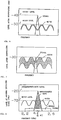
- the output level is saturated when the input level reaches about -20 dBm. With a loss of -10 dB due to passing-through being considered, the saturated output level is nearly -30 dBm. Therefore, the mixed wave has the level shown in Fig. 5 after the wave passes through the magnetostatic-wave filter 7 (threshold filter 5).
- the maximum level of the mixed wave which includes the levels of the interference wave and noise (including the spread signal), is -30 dBm.
- the spread signal is spread in reverse with a loss of about -20 dB.
- the signal has a level of -40 dBm, which differentiates from the noise level of -50 dBm, and the S/N ratio is 20 dB, as shown in Fig. 6.
- Fig. 7 shows S/N characteristics in a case in which the threshold filter circuit 5 is not used. Compared with a case in which the threshold filter circuit 5 is used as shown in Fig. 6, the noise level is increased by about 10 dB against the signal level.
- a spread-spectrum communication apparatus according to a second embodiment of the present invention will be described.
- a wide-band amplifier 31 In the circuit of this apparatus, between the threshold filter circuit 5 and the band-pass filter (BPF) 8 in the first-embodiment circuit shown in Fig. 1, a wide-band amplifier 31, a frequency converter 32, and an intermediate-frequency amplifier 33 are added as shown in Fig. 2.
- BPF band-pass filter
- an interference wave having a center frequency of 2.41 GHz is superimposed on a spread-spectrum wave having a center frequency of 2.4 GHz and a spread-signal band of 2.2 GHz to 2.6 GHz.
- the interference wave has a level of -20 dBm.
- the spread signal has a level equal to or less than a noise level of -70 dBm.
- the level of the interference wave becomes 30 dBm and the noise (including the signal) level becomes -20 dBm.
- the mixed wave which has been amplified a total of 50 dB after it was input into an antenna, is input to a magnetostatic-wave filter 27. Since this filter has a saturation output level of about -20 dBm, the mixed wave has a level of -30 dBm, which is the result of adding the interference level and the noise (including the signal) level, after the wave passes through the magnetostatic-wave filter 27 (threshold filter 25).
- the mixed wave output from the threshold filter 25 is amplified by 20 dB in the wide-band amplifier 31 and is input to the frequency converter 32.
- a signal having a local-oscillation frequency fLO of 2.8 GHz and a level of -10 dBm is input to the frequency converter 32, is converted to a signal having an intermediate frequency of 400 MHz, is amplified by 20 dB by the amplifier 33, and then is input to the band-pass filter (BPF) 8. Since the circuit stages following the band-pass filter 8 are the same as those described in the first embodiment, the same numbers are used to indicate them and the descriptions thereof are omitted.
- the circuit shown in the second embodiment is especially useful in cases where the spread-signal frequency band is wide, and a high carrier frequency and large spread-code coefficients are used. It also benefits from the advantage that the magnetostatic-wave filter is able to be used in a high-frequency band, in which the filter exhibits better characteristics.
Landscapes
- Engineering & Computer Science (AREA)
- Computer Networks & Wireless Communication (AREA)
- Signal Processing (AREA)
- Noise Elimination (AREA)
Applications Claiming Priority (6)
| Application Number | Priority Date | Filing Date | Title |
|---|---|---|---|
| JP31321895 | 1995-11-30 | ||
| JP313218/95 | 1995-11-30 | ||
| JP31321895 | 1995-11-30 | ||
| JP8282236A JPH09214397A (ja) | 1995-11-30 | 1996-10-24 | スペクトル拡散通信装置 |
| JP282236/96 | 1996-10-24 | ||
| JP28223696 | 1996-10-24 |
Publications (3)
| Publication Number | Publication Date |
|---|---|
| EP0777337A2 true EP0777337A2 (de) | 1997-06-04 |
| EP0777337A3 EP0777337A3 (de) | 2000-03-29 |
| EP0777337B1 EP0777337B1 (de) | 2002-09-04 |
Family
ID=26554523
Family Applications (1)
| Application Number | Title | Priority Date | Filing Date |
|---|---|---|---|
| EP96119012A Expired - Lifetime EP0777337B1 (de) | 1995-11-30 | 1996-11-27 | Spreizspektrum-Nachrichtenübertragungsgerät |
Country Status (4)
| Country | Link |
|---|---|
| US (1) | US5930287A (de) |
| EP (1) | EP0777337B1 (de) |
| JP (1) | JPH09214397A (de) |
| DE (1) | DE69623418T2 (de) |
Cited By (3)
| Publication number | Priority date | Publication date | Assignee | Title |
|---|---|---|---|---|
| WO2003098256A1 (en) * | 2002-05-20 | 2003-11-27 | Sige Semiconductor Inc. | Gps receiver with improved immunity to burst transmissions |
| US7761072B2 (en) | 2005-12-14 | 2010-07-20 | Sige Semiconductor (Europe) Limited | GPS receiver with improved immunity to burst transmissions |
| US11212702B2 (en) | 2017-03-08 | 2021-12-28 | Sony Semiconductor Solutions Corporation | Signal processing apparatus and method |
Families Citing this family (2)
| Publication number | Priority date | Publication date | Assignee | Title |
|---|---|---|---|---|
| JP2976281B2 (ja) * | 1997-02-07 | 1999-11-10 | 株式会社村田製作所 | スペクトル拡散通信装置 |
| CA2664502A1 (en) * | 2008-04-29 | 2009-10-29 | Hany Shenouda | Transceiver architecture |
Family Cites Families (7)
| Publication number | Priority date | Publication date | Assignee | Title |
|---|---|---|---|---|
| JPH0644255A (ja) * | 1991-05-17 | 1994-02-18 | Shimizu Corp | 統合的生産プロジェクト情報管理システム |
| US5317289A (en) * | 1992-02-14 | 1994-05-31 | Uniden Corporation | Frequency-fluctuating interference removed receiver |
| JP2561232B2 (ja) * | 1992-08-31 | 1996-12-04 | 双葉電子工業株式会社 | スぺクトラム拡散受信装置及びこの装置を用いたスぺクトラム拡散送受信装置 |
| GB2274374B (en) * | 1993-01-15 | 1997-01-22 | Marconi Gec Ltd | Communication system |
| EP0634666A3 (de) * | 1993-06-28 | 1997-08-20 | Victor Company Of Japan | Empfänger zum Empfangen und Demodulieren von spreizspektrummodulierten GPS-Signalen. |
| US5404375A (en) * | 1993-08-23 | 1995-04-04 | Westinghouse Electric Corp. | Process and apparatus for satellite data communication |
| JP3132399B2 (ja) * | 1996-10-02 | 2001-02-05 | 株式会社村田製作所 | スペクトル拡散通信装置 |
-
1996
- 1996-10-24 JP JP8282236A patent/JPH09214397A/ja active Pending
- 1996-11-27 DE DE69623418T patent/DE69623418T2/de not_active Expired - Lifetime
- 1996-11-27 EP EP96119012A patent/EP0777337B1/de not_active Expired - Lifetime
- 1996-11-27 US US08/757,294 patent/US5930287A/en not_active Expired - Lifetime
Non-Patent Citations (1)
| Title |
|---|
| IEEE TRANSACTIONS ON COMMUNICATIONS, vol. 37, no. 12, December 1989 (1989-12-01) |
Cited By (5)
| Publication number | Priority date | Publication date | Assignee | Title |
|---|---|---|---|---|
| WO2003098256A1 (en) * | 2002-05-20 | 2003-11-27 | Sige Semiconductor Inc. | Gps receiver with improved immunity to burst transmissions |
| US6947840B2 (en) | 2002-05-20 | 2005-09-20 | Sige Semiconductor Inc. | GPS receiver with improved immunity to burst transmissions |
| CN100434930C (zh) * | 2002-05-20 | 2008-11-19 | SiGe半导体公司 | 具有改进抗突发传输功能的gps接收机 |
| US7761072B2 (en) | 2005-12-14 | 2010-07-20 | Sige Semiconductor (Europe) Limited | GPS receiver with improved immunity to burst transmissions |
| US11212702B2 (en) | 2017-03-08 | 2021-12-28 | Sony Semiconductor Solutions Corporation | Signal processing apparatus and method |
Also Published As
| Publication number | Publication date |
|---|---|
| EP0777337A3 (de) | 2000-03-29 |
| DE69623418T2 (de) | 2003-01-09 |
| US5930287A (en) | 1999-07-27 |
| DE69623418D1 (de) | 2002-10-10 |
| EP0777337B1 (de) | 2002-09-04 |
| JPH09214397A (ja) | 1997-08-15 |
Similar Documents
| Publication | Publication Date | Title |
|---|---|---|
| US5978362A (en) | Method and apparatus for eliminating intermodulation interference in cellular telephone systems | |
| JP2993558B2 (ja) | 受信機 | |
| EP1182788A1 (de) | Verfahren und Vorrichtung zum Reduktion von der Amplitude der Nachbarfrequenzen | |
| KR20050025231A (ko) | 스펙트럼 확산통신방식 수신장치 | |
| US6959170B2 (en) | Communications receivers and methods therefor | |
| WO2004086654A1 (en) | Apparatus for processing digital if signals capable of detecting jamming signals | |
| KR20010041572A (ko) | 협대역 간섭 신호 존재시 수신기의 동적 범위를향상시키기 위한 장치, 시스템 및 방법 | |
| US5930287A (en) | Spread-spectrum communication apparatus | |
| EP0834998B1 (de) | Spreizspektrumempfänger mit Schmallbandstörungsunterdrückung | |
| JP3699026B2 (ja) | 無線受信機自動利得制御方法及び装置 | |
| US6975264B2 (en) | Signal separating system | |
| EP0600641B1 (de) | Adaptive Löschvorrichtung für aneinandergrenzende Bandfilter | |
| US20050227637A1 (en) | Signal enhancement | |
| JPH0810841B2 (ja) | スペクトラム拡散通信装置 | |
| JP4336009B2 (ja) | スペクトラム拡散変復調方法及びその装置 | |
| KR0130516B1 (ko) | 무선통신 시스템의 수신장치 | |
| JP2845201B2 (ja) | 合成方式のダイバーシティ受信機 | |
| KR100424623B1 (ko) | 직접 변환 방식에 따른 이동 통신 단말의 수신 장치 | |
| JP2861877B2 (ja) | 受信装置 | |
| JP3264188B2 (ja) | スペクトル拡散通信装置 | |
| JP2000036803A (ja) | スペクトラム拡散通信装置 | |
| JPH09214396A (ja) | スペクトル拡散通信装置 | |
| KR19990058821A (ko) | 무선 가입자망 시스템 단말기를 위한 수신 회로및 수신 방법 | |
| JPH11163829A (ja) | スペクトラム拡散通信装置 | |
| JP2001102948A (ja) | 移動局 |
Legal Events
| Date | Code | Title | Description |
|---|---|---|---|
| PUAI | Public reference made under article 153(3) epc to a published international application that has entered the european phase |
Free format text: ORIGINAL CODE: 0009012 |
|
| 17P | Request for examination filed |
Effective date: 19961127 |
|
| AK | Designated contracting states |
Kind code of ref document: A2 Designated state(s): DE FR GB |
|
| PUAL | Search report despatched |
Free format text: ORIGINAL CODE: 0009013 |
|
| AK | Designated contracting states |
Kind code of ref document: A3 Designated state(s): DE FR GB |
|
| 17Q | First examination report despatched |
Effective date: 20000613 |
|
| GRAG | Despatch of communication of intention to grant |
Free format text: ORIGINAL CODE: EPIDOS AGRA |
|
| GRAG | Despatch of communication of intention to grant |
Free format text: ORIGINAL CODE: EPIDOS AGRA |
|
| GRAH | Despatch of communication of intention to grant a patent |
Free format text: ORIGINAL CODE: EPIDOS IGRA |
|
| GRAH | Despatch of communication of intention to grant a patent |
Free format text: ORIGINAL CODE: EPIDOS IGRA |
|
| GRAA | (expected) grant |
Free format text: ORIGINAL CODE: 0009210 |
|
| AK | Designated contracting states |
Kind code of ref document: B1 Designated state(s): DE FR GB |
|
| REG | Reference to a national code |
Ref country code: GB Ref legal event code: FG4D |
|
| REF | Corresponds to: |
Ref document number: 69623418 Country of ref document: DE Date of ref document: 20021010 |
|
| ET | Fr: translation filed | ||
| PLBE | No opposition filed within time limit |
Free format text: ORIGINAL CODE: 0009261 |
|
| STAA | Information on the status of an ep patent application or granted ep patent |
Free format text: STATUS: NO OPPOSITION FILED WITHIN TIME LIMIT |
|
| 26N | No opposition filed |
Effective date: 20030605 |
|
| REG | Reference to a national code |
Ref country code: FR Ref legal event code: PLFP Year of fee payment: 20 |
|
| PGFP | Annual fee paid to national office [announced via postgrant information from national office to epo] |
Ref country code: GB Payment date: 20151118 Year of fee payment: 20 Ref country code: DE Payment date: 20151119 Year of fee payment: 20 |
|
| PGFP | Annual fee paid to national office [announced via postgrant information from national office to epo] |
Ref country code: FR Payment date: 20151119 Year of fee payment: 20 |
|
| REG | Reference to a national code |
Ref country code: DE Ref legal event code: R071 Ref document number: 69623418 Country of ref document: DE |
|
| REG | Reference to a national code |
Ref country code: GB Ref legal event code: PE20 Expiry date: 20161126 |
|
| PG25 | Lapsed in a contracting state [announced via postgrant information from national office to epo] |
Ref country code: GB Free format text: LAPSE BECAUSE OF EXPIRATION OF PROTECTION Effective date: 20161126 |