EP0777382A2 - Verfahren und Vorrichtung zum Auswählen eines Rundfunkkanals - Google Patents
Verfahren und Vorrichtung zum Auswählen eines Rundfunkkanals Download PDFInfo
- Publication number
- EP0777382A2 EP0777382A2 EP96308538A EP96308538A EP0777382A2 EP 0777382 A2 EP0777382 A2 EP 0777382A2 EP 96308538 A EP96308538 A EP 96308538A EP 96308538 A EP96308538 A EP 96308538A EP 0777382 A2 EP0777382 A2 EP 0777382A2
- Authority
- EP
- European Patent Office
- Prior art keywords
- broadcast system
- channel selection
- signal
- channel
- discrimination
- Prior art date
- Legal status (The legal status is an assumption and is not a legal conclusion. Google has not performed a legal analysis and makes no representation as to the accuracy of the status listed.)
- Granted
Links
Images


Classifications
-
- H—ELECTRICITY
- H04—ELECTRIC COMMUNICATION TECHNIQUE
- H04N—PICTORIAL COMMUNICATION, e.g. TELEVISION
- H04N5/00—Details of television systems
- H04N5/44—Receiver circuitry for the reception of television signals according to analogue transmission standards
- H04N5/50—Tuning indicators; Automatic tuning control
-
- H—ELECTRICITY
- H04—ELECTRIC COMMUNICATION TECHNIQUE
- H04N—PICTORIAL COMMUNICATION, e.g. TELEVISION
- H04N5/00—Details of television systems
- H04N5/44—Receiver circuitry for the reception of television signals according to analogue transmission standards
- H04N5/46—Receiver circuitry for the reception of television signals according to analogue transmission standards for receiving on more than one standard at will
Definitions
- the present invention relates to a television receiver for a multi-broadcast system in which circuits concerning a broadcast system are automatically selected according to the receiving television broadcast system.
- FIG. 4 A block diagram of an automatic discrimination selection apparatus is shown in FIG. 4.
- an rf input signal is detected at a tuner 21 and if a modulated sound signal is contained in the detected baseband signal (video signal) is judged at judge means A.
- the judge means A includes a band pass filters 27 and 28, an amplifier 29, an ac/dc converter 30 and a comparator 31.
- PAL Phase Alternation by Line
- SECAM Serial Color And Memory
- MAC Multiplexed Analog Component
- automatic judge means like the above-mentioned has problems that it can not suitably discriminate the broadcast systems at a fringe area or can judge only a specific broadcast system and is an imperfect system having problems such as malfunction.
- circuits are sometimes configured so that not only automatic selection means of the circuits by automatic discrimination of the broadcast system but also a circuit which can select a circuit suitable for a specific broadcast system manually and forcibly can be selected.
- the present invention aims to present a channel selection method and apparatus which can automatically select a desired broadcast system without a television viewer directs to select the circuits by manual handling even under a circumstance that the viewer can manually (by force) select the circuits suitable for a specific broadcast system.
- the resent invention presents a channel selection method having:
- the present invention presents a channel selection apparatus including:
- the broadcast system of the received signal can be discriminated at every channel selection.
- the present invention presents a channel selection apparatus further including:
- the state in which the circuits concerning broadcast systems are manually selected so as to match with a broadcast system of the receiving signal is fixed and it is impossible to automatically select as long as the state is not reset.
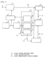
- FIG. 1 is a block diagram of a channel selection apparatus in accordance with a first exemplary embodiment of the present invention. (claim 1)
- FIG. 2 is a block diagram of a channel selection apparatus including an automatic selection part of color demodulation circuit in accordance with a second exemplary embodiment of the present invention. (claim 2)
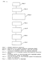
- FIG. 3 is a flow chart of a channel selection method in accordance with the present invention. (claim 4)
- FIG. 4 is a block diagram of an automatic discrimination selection apparatus for a multi-broadcast system in accordance with the prior art.
- FIGs. 1 and 2 A channel selection apparatus in accordance with the present invention is explained below using FIGs. 1 and 2.
- FIG. 1 is a block diagram of a channel selection apparatus in accordance with the first exemplary embodiment of the present invention and includes peripheral blocks necessary for explanation.
- a tuning/if amplification/detection means 6 selects a television signal of the channel corresponding to a tuning voltage supplied from tuning voltage generation means 7 out of one or more television signals inputted to an input terminal 9, amplifies the selected signal, detects and outputs as a video signal 18.
- the receiving channel can be selected by generating a tuning voltage corresponding to the channel directed by channel selection direction means 8 at the tuning voltage generation means 7.
- Channel selection direction means 8 is composed of a remote controller or push buttons provided on a television receiver itself and the channel selection is made by a usual way such as a direct selection to directly direct a channel number, an up/down selection to change channel numbers in order or the like using a direction signal outputted from channel selection direction means 8.
- a channel selection request means 1 detects that a channel selection was directed by channel selection direction means 8 and outputs a channel selection direction signal 14 to a channel selection judge part 2.
- the channel selection judge part 2 is composed of a channel entry state setting part 12, an on-screen selection part 13 and a broadcast system discrimination direction part 11.
- the channel entry state setting part 12 selects a selection state of a tuning voltage to tuning voltage generation means 7 according to the channel selection direction signal 14.
- the on-screen selection part 13 processes to display a channel number and the like on a CRT screen according to the channel selection direction signal 14.
- the broadcast system discrimination direction part 11 outputs a broadcast system discrimination direction signal 15 to a broadcast system discrimination part 3 and works the broadcast system discrimination part 3 according to the channel selection direction signal 14.
- the broadcast system discrimination part 3 is worked by the broadcast system discrimination direction signal 15, analyzes the video signal 18 outputted from the tuning/if amplification/ detection means 6, discriminates the broadcast systems and outputs a broadcast system discrimination signal 16.
- a general technique such as if a modulated sound signal is superimposed on the detected video signal 18, what the carrier frequency of the modulated sound signal is or the like.
- the broadcast system of the receiving signal can be automatically discriminated at every channel selection.
- FIG. 2 is a block diagram of a channel selection apparatus in accordance with the second exemplary embodiment of the present invention and includes peripheral blocks necessary for explanation.
- a color system selection part 4 receives a broadcast system discrimination signal 16 outputted from a broadcast system discrimination part 3 at every channel selection and outputs a color demodulation control signal 17 directing to select a color demodulation circuit suitable for the discriminated broadcast system to a video processing part 5.
- the video processing part 5 selects a circuit by the color demodulation control signal 17 and demodulates color according to the color demodulation control signal 17.
- a channel selection apparatus in accordance with the third exemplary embodiment of the present invention is quite same as that of the second exemplary embodiment except that in FIG. 2, channel selection request means 1 generates a channel selection direction signal 14 only in the case in which the signal outputted from channel selection direction means 8 is not for an up/down channel selection but for a direct channel selection by channel number.
- a channel selection judge part 2, a broadcast system discrimination part 3 and a color system selection part 4 can be composed of a microprocessor in common in the above three exemplary embodiments.
- FIG. 3 A flow chart showing a method to automatically select the circuits is shown in FIG. 3. Referring to FIG. 3,
- the broadcast system is automatically selected at every channel selection, a color demodulation circuit suitable for the broadcast system is selected. Therefore, it is possible to automatically select a suitable color demodulation circuit and the channel selection procedure becomes simple without taking a complex procedure, except in the case in which the broadcast system is hard to be discriminated for the selected channel due to at a fringe area reception or the like.
- the television viewer selects a color demodulation circuit for a specific broadcast system by a manual handling and can watch a correct picture, only in the case in which, for example, the selected channel is difficult to automatically discriminate the broadcast systems because of a fringe area reception.
- the broadcast systems can be automatically discriminated and the color demodulation circuits can be automatically selected, when a different channel is newly selected,
Landscapes
- Engineering & Computer Science (AREA)
- Multimedia (AREA)
- Signal Processing (AREA)
- Circuits Of Receivers In General (AREA)
- Channel Selection Circuits, Automatic Tuning Circuits (AREA)
- Color Television Systems (AREA)
- Processing Of Color Television Signals (AREA)
- Television Receiver Circuits (AREA)
- Two-Way Televisions, Distribution Of Moving Picture Or The Like (AREA)
Applications Claiming Priority (3)
| Application Number | Priority Date | Filing Date | Title |
|---|---|---|---|
| JP308602/95 | 1995-11-28 | ||
| JP30860295A JP3283411B2 (ja) | 1995-11-28 | 1995-11-28 | チャンネル選局装置 |
| JP30860295 | 1995-11-28 |
Publications (3)
| Publication Number | Publication Date |
|---|---|
| EP0777382A2 true EP0777382A2 (de) | 1997-06-04 |
| EP0777382A3 EP0777382A3 (de) | 1999-01-20 |
| EP0777382B1 EP0777382B1 (de) | 2002-02-06 |
Family
ID=17983019
Family Applications (1)
| Application Number | Title | Priority Date | Filing Date |
|---|---|---|---|
| EP96308538A Expired - Lifetime EP0777382B1 (de) | 1995-11-28 | 1996-11-26 | Verfahren und Vorrichtung zum Detektieren des Übertragungstandards eines ausgwählten Fernsehkanals |
Country Status (5)
| Country | Link |
|---|---|
| EP (1) | EP0777382B1 (de) |
| JP (1) | JP3283411B2 (de) |
| KR (1) | KR100306962B1 (de) |
| CN (1) | CN1131634C (de) |
| DE (1) | DE69619076T2 (de) |
Cited By (3)
| Publication number | Priority date | Publication date | Assignee | Title |
|---|---|---|---|---|
| EP0966158A3 (de) * | 1998-06-19 | 2000-07-19 | Sharp Kabushiki Kaisha | Videosignalprozessor zum Verarbeiten eines Videosignals mittels mehreren durch Daten angesteuerten Prozessoren und Fernsehempfänger zu deren Verwendung |
| FR2795851A1 (fr) * | 1999-06-04 | 2001-01-05 | Denso Corp | Recepteur multi-standards |
| WO2009077898A1 (en) * | 2007-12-14 | 2009-06-25 | Arcelik Anonim Sirketi | A broadcast receiving device and control method |
Families Citing this family (4)
| Publication number | Priority date | Publication date | Assignee | Title |
|---|---|---|---|---|
| KR100671299B1 (ko) * | 2004-11-15 | 2007-01-19 | 삼성전자주식회사 | 텔레비전 장치 및 텔레비전 장치의 제어방법 |
| WO2006062551A1 (en) * | 2004-12-06 | 2006-06-15 | Thomson Licensing | Network managed channel change in digital networks |
| CN102457685A (zh) * | 2010-10-20 | 2012-05-16 | Tcl集团股份有限公司 | 频道切换方法及采用该方法的电视机 |
| CN102256082B (zh) * | 2011-07-25 | 2013-09-18 | 广州视源电子科技股份有限公司 | 一种支持多种数字电视制式的电视机 |
Citations (1)
| Publication number | Priority date | Publication date | Assignee | Title |
|---|---|---|---|---|
| JPH05252455A (ja) | 1992-03-04 | 1993-09-28 | Mitsubishi Electric Corp | 放送方式の自動識別切換装置 |
Family Cites Families (3)
| Publication number | Priority date | Publication date | Assignee | Title |
|---|---|---|---|---|
| US4688082A (en) * | 1984-05-23 | 1987-08-18 | Sharp Kabushiki Kaisha | Multi-system television receiver |
| JPH01137890A (ja) * | 1987-11-25 | 1989-05-30 | Toshiba Corp | 放送方式判別回路 |
| JP3261806B2 (ja) * | 1993-06-07 | 2002-03-04 | 松下電器産業株式会社 | カラーシステム判別回路 |
-
1995
- 1995-11-28 JP JP30860295A patent/JP3283411B2/ja not_active Expired - Fee Related
-
1996
- 1996-11-26 KR KR1019960057246A patent/KR100306962B1/ko not_active Expired - Fee Related
- 1996-11-26 EP EP96308538A patent/EP0777382B1/de not_active Expired - Lifetime
- 1996-11-26 DE DE69619076T patent/DE69619076T2/de not_active Expired - Fee Related
- 1996-11-28 CN CN96118592A patent/CN1131634C/zh not_active Expired - Fee Related
Patent Citations (1)
| Publication number | Priority date | Publication date | Assignee | Title |
|---|---|---|---|---|
| JPH05252455A (ja) | 1992-03-04 | 1993-09-28 | Mitsubishi Electric Corp | 放送方式の自動識別切換装置 |
Cited By (4)
| Publication number | Priority date | Publication date | Assignee | Title |
|---|---|---|---|---|
| EP0966158A3 (de) * | 1998-06-19 | 2000-07-19 | Sharp Kabushiki Kaisha | Videosignalprozessor zum Verarbeiten eines Videosignals mittels mehreren durch Daten angesteuerten Prozessoren und Fernsehempfänger zu deren Verwendung |
| US6525777B2 (en) | 1998-06-19 | 2003-02-25 | Sharp Kabushiki Kaisha | Video signal processor processing video signal by plurality of data driven processors and television receiver using the same |
| FR2795851A1 (fr) * | 1999-06-04 | 2001-01-05 | Denso Corp | Recepteur multi-standards |
| WO2009077898A1 (en) * | 2007-12-14 | 2009-06-25 | Arcelik Anonim Sirketi | A broadcast receiving device and control method |
Also Published As
| Publication number | Publication date |
|---|---|
| JP3283411B2 (ja) | 2002-05-20 |
| EP0777382B1 (de) | 2002-02-06 |
| DE69619076T2 (de) | 2002-06-20 |
| CN1158534A (zh) | 1997-09-03 |
| JPH09149422A (ja) | 1997-06-06 |
| DE69619076D1 (de) | 2002-03-21 |
| KR100306962B1 (ko) | 2001-11-30 |
| CN1131634C (zh) | 2003-12-17 |
| EP0777382A3 (de) | 1999-01-20 |
| KR970026610A (ko) | 1997-06-24 |
Similar Documents
| Publication | Publication Date | Title |
|---|---|---|
| JP2906462B2 (ja) | テレビジョン受信機 | |
| US6108044A (en) | Receiver for receiving both HDTV and NTSC and method for selecting received signals | |
| EP0777382B1 (de) | Verfahren und Vorrichtung zum Detektieren des Übertragungstandards eines ausgwählten Fernsehkanals | |
| US5712690A (en) | Apparatus and method for diagnosing received broadcast signals using sync signals and signal level | |
| JPH1198422A (ja) | 映像信号判別回路 | |
| JP2591574B2 (ja) | 放送方式自動選択装置 | |
| US5305382A (en) | Satellite broadcast receiver | |
| US6707917B1 (en) | Monaural and stereo audio signal control system | |
| CN102209255B (zh) | 带有声音信号检测的电视信号接收机装置 | |
| KR20010001249A (ko) | 멀티방송시스템에서의 주방송 시스템에 따른 온스크린디스플레이 랭기지 자동 절환장치 | |
| JPH0723304A (ja) | 映像信号選択回路の信号検出回路 | |
| JP2950186B2 (ja) | テレビジョン受信機 | |
| JPH07212800A (ja) | 放送方式判別装置 | |
| KR100275677B1 (ko) | 방송신호 검파방식 자동 설정방법 | |
| KR970004924Y1 (ko) | 방송방식 자동 전환회로 | |
| KR0178901B1 (ko) | 와이드비젼 텔레비젼 수신기의 수직 사이즈 자동제어회로 | |
| KR19980047420A (ko) | 방송방식 판별기능을 갖는 채널자동선국장치 | |
| KR0141241B1 (ko) | 노이즈 제한회로 | |
| KR19990025768A (ko) | 티브이의 외부입력신호 자동 탐색 절환 장치와 방법. | |
| KR19990025660A (ko) | 자동으로 영상잡음을 제거할 수 있는 방법 및 그 장치 | |
| KR19990043329A (ko) | Pip 텔레비전의 탐색시간별 2방송방식 디스플레이장치 | |
| KR19990031458A (ko) | 주,부화면의 스테레오/모노 차별 표시방법 | |
| JPH05344511A (ja) | 衛星放送受信システム | |
| KR20000007324A (ko) | 사운드방식자동설정방법 | |
| JPS63179670A (ja) | 電界強度表示装置 |
Legal Events
| Date | Code | Title | Description |
|---|---|---|---|
| PUAI | Public reference made under article 153(3) epc to a published international application that has entered the european phase |
Free format text: ORIGINAL CODE: 0009012 |
|
| AK | Designated contracting states |
Kind code of ref document: A2 Designated state(s): DE FR GB |
|
| PUAL | Search report despatched |
Free format text: ORIGINAL CODE: 0009013 |
|
| AK | Designated contracting states |
Kind code of ref document: A3 Designated state(s): DE FR GB |
|
| 17P | Request for examination filed |
Effective date: 19990607 |
|
| GRAG | Despatch of communication of intention to grant |
Free format text: ORIGINAL CODE: EPIDOS AGRA |
|
| RTI1 | Title (correction) |
Free format text: METHOD AND APPARATUS FOR DETECTING THE BROADCASTING STANDARD OF A SELECTED TELEVISION CHANNEL |
|
| 17Q | First examination report despatched |
Effective date: 20010319 |
|
| GRAG | Despatch of communication of intention to grant |
Free format text: ORIGINAL CODE: EPIDOS AGRA |
|
| GRAG | Despatch of communication of intention to grant |
Free format text: ORIGINAL CODE: EPIDOS AGRA |
|
| GRAH | Despatch of communication of intention to grant a patent |
Free format text: ORIGINAL CODE: EPIDOS IGRA |
|
| GRAH | Despatch of communication of intention to grant a patent |
Free format text: ORIGINAL CODE: EPIDOS IGRA |
|
| GRAA | (expected) grant |
Free format text: ORIGINAL CODE: 0009210 |
|
| REG | Reference to a national code |
Ref country code: GB Ref legal event code: IF02 |
|
| AK | Designated contracting states |
Kind code of ref document: B1 Designated state(s): DE FR GB |
|
| REF | Corresponds to: |
Ref document number: 69619076 Country of ref document: DE Date of ref document: 20020321 |
|
| ET | Fr: translation filed | ||
| PLBE | No opposition filed within time limit |
Free format text: ORIGINAL CODE: 0009261 |
|
| STAA | Information on the status of an ep patent application or granted ep patent |
Free format text: STATUS: NO OPPOSITION FILED WITHIN TIME LIMIT |
|
| 26N | No opposition filed |
Effective date: 20021107 |
|
| PGFP | Annual fee paid to national office [announced via postgrant information from national office to epo] |
Ref country code: DE Payment date: 20081120 Year of fee payment: 13 |
|
| PGFP | Annual fee paid to national office [announced via postgrant information from national office to epo] |
Ref country code: FR Payment date: 20081112 Year of fee payment: 13 |
|
| PGFP | Annual fee paid to national office [announced via postgrant information from national office to epo] |
Ref country code: GB Payment date: 20081126 Year of fee payment: 13 |
|
| GBPC | Gb: european patent ceased through non-payment of renewal fee |
Effective date: 20091126 |
|
| REG | Reference to a national code |
Ref country code: FR Ref legal event code: ST Effective date: 20100730 |
|
| PG25 | Lapsed in a contracting state [announced via postgrant information from national office to epo] |
Ref country code: FR Free format text: LAPSE BECAUSE OF NON-PAYMENT OF DUE FEES Effective date: 20091130 |
|
| PG25 | Lapsed in a contracting state [announced via postgrant information from national office to epo] |
Ref country code: DE Free format text: LAPSE BECAUSE OF NON-PAYMENT OF DUE FEES Effective date: 20100601 |
|
| PG25 | Lapsed in a contracting state [announced via postgrant information from national office to epo] |
Ref country code: GB Free format text: LAPSE BECAUSE OF NON-PAYMENT OF DUE FEES Effective date: 20091126 |