EP0777984A2 - Boucle de ceinture de sécurité comprenant une languette liée à la boucle - Google Patents
Boucle de ceinture de sécurité comprenant une languette liée à la boucle Download PDFInfo
- Publication number
- EP0777984A2 EP0777984A2 EP96119615A EP96119615A EP0777984A2 EP 0777984 A2 EP0777984 A2 EP 0777984A2 EP 96119615 A EP96119615 A EP 96119615A EP 96119615 A EP96119615 A EP 96119615A EP 0777984 A2 EP0777984 A2 EP 0777984A2
- Authority
- EP
- European Patent Office
- Prior art keywords
- locking element
- locking
- tongue
- closure according
- lever
- Prior art date
- Legal status (The legal status is an assumption and is not a legal conclusion. Google has not performed a legal analysis and makes no representation as to the accuracy of the status listed.)
- Granted
Links
- 230000033001 locomotion Effects 0.000 claims abstract description 32
- 238000003780 insertion Methods 0.000 claims abstract description 24
- 230000037431 insertion Effects 0.000 claims abstract description 24
- 230000005540 biological transmission Effects 0.000 claims description 8
- 230000000903 blocking effect Effects 0.000 claims description 3
- 230000007704 transition Effects 0.000 claims description 2
- 238000006073 displacement reaction Methods 0.000 description 2
- 230000000694 effects Effects 0.000 description 2
- 230000035939 shock Effects 0.000 description 2
- 230000001133 acceleration Effects 0.000 description 1
- 230000006978 adaptation Effects 0.000 description 1
- 230000000284 resting effect Effects 0.000 description 1
- 230000001360 synchronised effect Effects 0.000 description 1
Images




Classifications
-
- A—HUMAN NECESSITIES
- A44—HABERDASHERY; JEWELLERY
- A44B—BUTTONS, PINS, BUCKLES, SLIDE FASTENERS, OR THE LIKE
- A44B11/00—Buckles; Similar fasteners for interconnecting straps or the like, e.g. for safety belts
- A44B11/25—Buckles; Similar fasteners for interconnecting straps or the like, e.g. for safety belts with two or more separable parts
- A44B11/2503—Safety buckles
- A44B11/2507—Safety buckles actuated by a push-button
- A44B11/2523—Safety buckles actuated by a push-button acting parallel to the main plane of the buckle and in the same direction as the fastening action
Definitions
- the invention relates to a closure according to the preamble of patent claim 1.
- the locking element has at its end enclosing the pivot axis a stop surface, via which a locking movement leading the locking element into its locking position is initiated when the tongue is inserted into the guide channel. Furthermore, a return spring is arranged between the locking element and the locking member, against the restoring force of which the actuating button transfers the locking element into the release position.
- the return spring which is arranged between the locking element and the locking member, is provided as the second spring. Furthermore, only a relatively low torque is introduced into the locking element when the locking element moves into its locking position because the stop surface provided on the locking element is provided at the end at which the pivot axis of the locking element lies.
- the object of the invention is therefore to provide a closure of the type mentioned, which has a simplified structure and in which the closing function is improved.
- the stop surface via which the insertion movement of the tongue into the locking element for moving the locking element into its locking position is initiated, is provided at the end which is remote from the pivot axis of the locking element. This results in a large lever arm with which the insertion movement of the tongue is transmitted to the locking element.
- the actuating lever transmitting the insertion movement of the tongue is supported on the displaceably mounted locking element, so that the insertion movement of the tongue is achieved for a synchronous movement of the locking element into its locking position and of the locking element into its locking position.
- the spring force imparted by the ejector spring acts as a support when moving the locking element in the direction of its locking position.
- the actuating lever is preferably designed as an angle lever, so that an effective transmission of the insertion movement of the tongue is achieved on the third stop surface on the locking element.
- the tongue or the ejector pushed back by the tongue in the guide channel acts on one lever arm and the second lever arm, which is angled opposite, on the third stop surface on the locking element.
- the actuating lever is pivoted about the axis formed on the locking element, the locking element is pivoted with its first stop surface in the direction of the guide channel to the point at which, after the insertion movement has ended, the engagement point comes to rest on the tongue at which the first stop surface of the locking element is in the locked position.
- the first phase of the pivoting movement of the locking element is in the locking position by the actuating lever causes.
- the locking element on the locking element comes into the plane in which the second stop surface lies on the locking element. Due to the force of the ejector spring transmitted to the locking element via the two-sided lever, the locking element is moved into its locking position until it bears against the second stop surface of the locking element, which is the final locking position of the locking element.
- the locking element In the area in which it rests with the locking element in the locking position, the locking element is designed such that it rests with a positive fit on the second stop surface of the locking element. In adaptation to a rectilinear second stop surface of the locking element, the locking element in the area or in the areas with which it rests on the locking element in the locking position can also be designed with straight surfaces.
- the locking element preferably has a square profile in this area.
- the locking element on the carrier is guided against rotation about its longitudinal axis.
- the locations of the locking element which bear on the carrier with sliding contact can have a positive fit with the carrier.
- This area or these areas of the locking element can also have a square profile.
- the two exemplary embodiments for a seat belt buckle shown in FIGS. 1 to 4 have a tongue 11 connected to a seat belt strap 19.
- the tongue 11 can be inserted into a guide channel 2, which is delimited in a carrier formed by two plates 20 and 21 (FIGS. 3 and 4).
- the locking element 1 is mounted at one end in a pivot axis 17 on the carrier 5.
- a bearing pin 23 fastened in bearing bores 24 of the carrier 5 is used to form the pivot axis 17.
- the bearing pin 23 is inserted through openings 25 at one end of the locking element 1 (FIG. 1).
- the pivot axis 17 of the locking element 1 running parallel to the insertion plane of the guide channel 2 is formed.
- projections 38 are formed on the locking element and are mounted in corresponding recesses 39 to form the pivot axis 17 on the carrier 5.
- a first stop surface 8 extending transversely to the guide channel 2 is formed.
- the tongue 11 bears against this stop surface 8 in the locking position (FIGS. 3 and 4).
- a second stop surface 9 is provided on the locking element. In the locked position (FIGS. 3 and 4), this second stop surface extends parallel to the insertion direction or insertion plane of the guide channel 2. against the second stop surface 9 of the locking element 1 is in the locking position, a locking element 4. This locking element 4 is mounted on the carrier 5 in a slot guide 26 parallel to the insertion level of the guide channel 2 to and fro.
- the locking element which is in the form of a pin, has a central region 27 with a round profile, in particular with a circular cross section. At both ends, the locking element 4 has a square profile 28.
- the double-sided square profile 28 creates a positive contact or sliding guide in the elongated hole guide 26, which is provided on both sides in the carrier 5, in particular on the board 21, in side legs. This prevents the locking element 4 from rotating about its longitudinal axis during the movement between the release position (FIG. 2) and its locking position (FIGS. 3 and 4).
- a form fit in the locking position is achieved by the one flat boundary surface of the respective square profile 28, which rests on the second rectilinear or flat second stop surface 9 of the locking element 1 (FIG. 5C).
- the force of an ejector spring 3 acts on the central region 27 of the blocking element 4 via a two-armed lever 7 supported on the carrier 5 and a rod-shaped rigid motion transmission element 16.
- the ejector spring 3 acts with its spring force in a known manner on an ejector 14 which is movable along the guide channel 2.
- the ejector spring 3 is supported at one end (the right end in the figure) directly on a lever arm of the two-sided lever 7.
- the ejector spring 3 is supported on a balancing mass 18 which is arranged between the ejector spring 3 and the one lever arm of the two-sided lever 7.
- the balancing mass 18 is used in a known manner to secure the closure against shock in the event of excessive acceleration.
- the two-sided lever 7 is pivotally mounted on the carrier 5 about an axis 29.
- Bearing holes 30 on the side legs of the board 21 form the bearing points of the lever axis 29.
- an actuating lever 12 is provided which is pivotably mounted on the locking element 4.
- the actuating lever 12 is preferably pivotally mounted on the round profile of the central region 27.
- the actuating lever 2 is designed as an angle lever with the lever arms 13 and 15.
- the insertion movement of the tongue 11 into the guide channel 2 is used.
- the ejector 14 is moved against the force of the ejector spring 3 (from left to right in FIGS. 2 to 4).
- the direction of insertion is indicated in FIGS. 3 and 4 by an arrow 31.
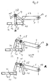
- the actuating lever 12 is pivoted counterclockwise from the position shown in FIGS. 2 and 5A about the longitudinal axis of the locking element 4.
- the ejector 14 engages the lever arm 13 during its movement in the guide channel 2 and pivots it accordingly, as is shown in FIG. 5B.
- the actuating lever 12 When the actuating lever 12 is pivoted counterclockwise, it presses with its lever arm 15 onto a third stop surface 10 of the locking element 1.
- the third stop surface 10 like the first and second stop surfaces 8 and 9, lies at the end of the locking element 1 opposite the pivot axis 17. Between the force introduction point formed in the third stop surface 10, into which the insertion movement of the tongue is introduced into the locking element 1 via the actuating lever 12 is, and the pivot axis 17 of the locking element is thus formed a large lever arm.
- the ejector spring 3 exerts a force F on the locking element 1 on the first stop surface 9, which force is directed in the opposite direction to the insertion direction 31. Since the pivot axis 17 is arranged offset with respect to the effective direction of the ejector spring 3 (FIG. 6), a resulting force component F2 acts on the locking element 1, which generates a moment on the locking element 1 in the direction of the release position. However, opening of the locking element 1 is prevented by the locking element 4 resting on the second stop surface 9 with its square profiles 28.
- a closed force-locking chain supported on the carrier 5 is formed, which acts in two directions, namely in the direction of insertion (arrow 31) and opposite thereto in the direction of the force F, the ejector spring 14, the part of the locking element 1 containing the stop surfaces 8 and 9, the locking element 4, the rigid movement transmission element 16, the two-sided lever 7 and optionally the balancing mass 8 (embodiment of Figures 1 to 3).
- This closed frictional chain ensures secure positioning of the individual parts, in particular the locking element 1 in the locking position.
- the actuation button 6 In order to return the locking element 1 from the locking position to the release position, the actuation button 6 is shifted in the direction of insertion (arrow 31). The actuation button 6 is displaced against a spring 35 which is supported, for example, integrally with the support 5, and moves the locking element 4 from the locking position in FIGS. 2 to 5 to the right.
- the ejector spring 3 When moving the locking element 4 along the slot guide 26, the ejector spring 3 is compressed via the two-sided lever 7 and exerts an increased force on the locking element 1 on the first stop surface 8 via the ejector 14, which generates an increased torque in the direction of the release position on the locking element 1.
- the square profiles 28 of the locking element 4 are displaced into the recess 32, the locking element is pivoted toward the release position due to this torque.
- This can be supported by an inclined ramp 36 formed on the locking element 1, which can come into engagement with the locking element 4, so that a movement on the locking element in the direction of its release position is also impressed or moved by the displacement movement of the locking element 4 from its locking position into the release position is initiated. Furthermore, an additional spring can be provided which is supported on the actuation button and on the locking element.
Landscapes
- Buckles (AREA)
- Automotive Seat Belt Assembly (AREA)
- Labeling Devices (AREA)
Applications Claiming Priority (2)
| Application Number | Priority Date | Filing Date | Title |
|---|---|---|---|
| DE19545899A DE19545899A1 (de) | 1995-12-08 | 1995-12-08 | Verschluß für einen Sicherheitsgurt mit einer mit dem Sicherheitsgurt verbundenen Steckzunge |
| DE19545899 | 1995-12-08 |
Publications (3)
| Publication Number | Publication Date |
|---|---|
| EP0777984A2 true EP0777984A2 (fr) | 1997-06-11 |
| EP0777984A3 EP0777984A3 (fr) | 1998-01-14 |
| EP0777984B1 EP0777984B1 (fr) | 2001-03-28 |
Family
ID=7779604
Family Applications (1)
| Application Number | Title | Priority Date | Filing Date |
|---|---|---|---|
| EP96119615A Expired - Lifetime EP0777984B1 (fr) | 1995-12-08 | 1996-12-06 | Boucle de ceinture de sécurité comprenant une languette liée à la boucle |
Country Status (3)
| Country | Link |
|---|---|
| EP (1) | EP0777984B1 (fr) |
| AT (1) | ATE200012T1 (fr) |
| DE (2) | DE19545899A1 (fr) |
Cited By (3)
| Publication number | Priority date | Publication date | Assignee | Title |
|---|---|---|---|---|
| DE19858716C1 (de) * | 1998-12-18 | 2000-05-18 | Breed Automotive Tech | Verschluß für einen Sicherheitsgurt |
| EP1025774A3 (fr) * | 1999-02-04 | 2001-01-17 | Breed Automotive Technology, Inc. | Boucle de ceinture de sécurité |
| CN104324463A (zh) * | 2014-11-04 | 2015-02-04 | 国家电网公司 | 一种安全带连环锁安全扣 |
Families Citing this family (1)
| Publication number | Priority date | Publication date | Assignee | Title |
|---|---|---|---|---|
| DE102008020789A1 (de) | 2008-04-25 | 2009-11-05 | Airbus Deutschland Gmbh | Befestigungssystem sowie Verfahren zum Befestigen eines Elementes einer Flugzeuginnenausstattung |
Citations (2)
| Publication number | Priority date | Publication date | Assignee | Title |
|---|---|---|---|---|
| DE2719325C2 (de) | 1976-04-28 | 1993-05-13 | Aciers et Outillage Peugeot, Audincourt | Verschluss für Sicherheitsgurte |
| DE4401291C1 (de) | 1994-01-18 | 1995-02-02 | Hs Tech & Design | Sicherheitsgurtverschluß |
Family Cites Families (5)
| Publication number | Priority date | Publication date | Assignee | Title |
|---|---|---|---|---|
| FR2509969A1 (fr) * | 1981-07-27 | 1983-01-28 | Klippan Nv | Boucle de fermeture de ceinture de securite a loquet pivotant |
| FR2525878A1 (fr) * | 1982-04-28 | 1983-11-04 | Klippan Nv | Boucle de ceinture de securite a loquet de blocage pivotant |
| DE3533684A1 (de) * | 1985-08-17 | 1987-02-26 | Autoflug Gmbh | Sicherheitsgurtverschluss |
| GB8904205D0 (en) * | 1989-02-23 | 1989-04-05 | Bsrd Ltd | Seat belt buckle |
| JPH05508785A (ja) * | 1990-07-13 | 1993-12-09 | アウトフルーク ゲゼルシヤフト ミツト ベシユレンクテル ハフツング ウント コンパニー フアールツオイクテヒニク | 安全ベルトバツクル |
-
1995
- 1995-12-08 DE DE19545899A patent/DE19545899A1/de not_active Withdrawn
-
1996
- 1996-12-06 EP EP96119615A patent/EP0777984B1/fr not_active Expired - Lifetime
- 1996-12-06 AT AT96119615T patent/ATE200012T1/de not_active IP Right Cessation
- 1996-12-06 DE DE59606664T patent/DE59606664D1/de not_active Expired - Fee Related
Patent Citations (2)
| Publication number | Priority date | Publication date | Assignee | Title |
|---|---|---|---|---|
| DE2719325C2 (de) | 1976-04-28 | 1993-05-13 | Aciers et Outillage Peugeot, Audincourt | Verschluss für Sicherheitsgurte |
| DE4401291C1 (de) | 1994-01-18 | 1995-02-02 | Hs Tech & Design | Sicherheitsgurtverschluß |
Cited By (7)
| Publication number | Priority date | Publication date | Assignee | Title |
|---|---|---|---|---|
| DE19858716C1 (de) * | 1998-12-18 | 2000-05-18 | Breed Automotive Tech | Verschluß für einen Sicherheitsgurt |
| EP1010378A3 (fr) * | 1998-12-18 | 2001-01-17 | Breed Automotive Technology, Inc. | Boucle de ceinture de sécurité |
| US6202269B1 (en) | 1998-12-18 | 2001-03-20 | Breed Automotive Technology, Inc. | Seat belt buckle |
| EP1025774A3 (fr) * | 1999-02-04 | 2001-01-17 | Breed Automotive Technology, Inc. | Boucle de ceinture de sécurité |
| US6266855B1 (en) | 1999-02-04 | 2001-07-31 | Breed Automotive Technology, Inc. | Seat belt buckle |
| CN104324463A (zh) * | 2014-11-04 | 2015-02-04 | 国家电网公司 | 一种安全带连环锁安全扣 |
| CN104324463B (zh) * | 2014-11-04 | 2018-01-30 | 国家电网公司 | 一种安全带连环锁安全扣 |
Also Published As
| Publication number | Publication date |
|---|---|
| EP0777984B1 (fr) | 2001-03-28 |
| DE19545899A1 (de) | 1997-06-12 |
| ATE200012T1 (de) | 2001-04-15 |
| DE59606664D1 (de) | 2001-05-03 |
| EP0777984A3 (fr) | 1998-01-14 |
Similar Documents
| Publication | Publication Date | Title |
|---|---|---|
| DE69120749T2 (de) | Verriegelungsvorrichtung zur Verwendung in einem Fahrzeug | |
| DE3937855C1 (fr) | ||
| EP0566036B1 (fr) | Dispositif de ligature pour des parties du corps humain, en particulier tourniquet | |
| EP0769433A2 (fr) | Enrouleur de ceinture de sécurité avec tensionneur et limitation de tension | |
| EP0823223B1 (fr) | Boucle stabilisée pour ceinture de sécurité à prétendeur | |
| EP1623796B1 (fr) | Pince | |
| EP0721304B1 (fr) | Systeme de verrouillage pour ceinture de securite | |
| EP0749629A1 (fr) | Interrupteur de securite | |
| DE3829109C2 (de) | Elektrischer Schalter, insbesondere Lenkstockschalter für Kraftfahrzeuge | |
| DE4321720C2 (de) | Verriegelungssystem | |
| EP0777984B1 (fr) | Boucle de ceinture de sécurité comprenant une languette liée à la boucle | |
| DE29914764U1 (de) | Zange | |
| DE3006151C2 (fr) | ||
| EP0896348A2 (fr) | Dispositif de verrouillage pour appareils de commutation | |
| DE3426577A1 (de) | Schere, insbesondere gartenschere | |
| EP1040064A1 (fr) | Systeme de prehension pour objets plans | |
| EP3945936B1 (fr) | Dispositif de chargement ou d'éjection | |
| DE29502987U1 (de) | Ausklinkbares Schnappschloß | |
| EP0464174B1 (fr) | Boucle de ceinture pour systemes de retenue de ceinture | |
| DE4401291C1 (de) | Sicherheitsgurtverschluß | |
| DE4123280C2 (de) | Gurtverschluß für einen Sicherheitsgurt eines Kraftfahrzeuges | |
| DE69808822T2 (de) | Selbstverriegelnder Faltverschluss für Uhrarmbänder | |
| DE8903389U1 (de) | Schloß, insbesondere für die Heckklappe eines Kraftfahrzeuges | |
| DE3837376A1 (de) | Gurtschloss fuer einen sicherheitsgurt eines fahrzeugs, insbesondere kraftfahrzeugs | |
| DE19719972A1 (de) | Sicherheitsgurtschloß |
Legal Events
| Date | Code | Title | Description |
|---|---|---|---|
| PUAI | Public reference made under article 153(3) epc to a published international application that has entered the european phase |
Free format text: ORIGINAL CODE: 0009012 |
|
| AK | Designated contracting states |
Kind code of ref document: A2 Designated state(s): AT DE ES FR GB IT |
|
| PUAL | Search report despatched |
Free format text: ORIGINAL CODE: 0009013 |
|
| AK | Designated contracting states |
Kind code of ref document: A3 Designated state(s): AT DE ES FR GB IT |
|
| 17P | Request for examination filed |
Effective date: 19980701 |
|
| GRAG | Despatch of communication of intention to grant |
Free format text: ORIGINAL CODE: EPIDOS AGRA |
|
| 17Q | First examination report despatched |
Effective date: 20000620 |
|
| GRAG | Despatch of communication of intention to grant |
Free format text: ORIGINAL CODE: EPIDOS AGRA |
|
| GRAH | Despatch of communication of intention to grant a patent |
Free format text: ORIGINAL CODE: EPIDOS IGRA |
|
| GRAH | Despatch of communication of intention to grant a patent |
Free format text: ORIGINAL CODE: EPIDOS IGRA |
|
| GRAA | (expected) grant |
Free format text: ORIGINAL CODE: 0009210 |
|
| AK | Designated contracting states |
Kind code of ref document: B1 Designated state(s): AT DE ES FR GB IT |
|
| REF | Corresponds to: |
Ref document number: 200012 Country of ref document: AT Date of ref document: 20010415 Kind code of ref document: T |
|
| REF | Corresponds to: |
Ref document number: 59606664 Country of ref document: DE Date of ref document: 20010503 |
|
| ITF | It: translation for a ep patent filed | ||
| GBT | Gb: translation of ep patent filed (gb section 77(6)(a)/1977) |
Effective date: 20010504 |
|
| ET | Fr: translation filed | ||
| PG25 | Lapsed in a contracting state [announced via postgrant information from national office to epo] |
Ref country code: ES Free format text: LAPSE BECAUSE OF FAILURE TO SUBMIT A TRANSLATION OF THE DESCRIPTION OR TO PAY THE FEE WITHIN THE PRESCRIBED TIME-LIMIT Effective date: 20010927 |
|
| PGFP | Annual fee paid to national office [announced via postgrant information from national office to epo] |
Ref country code: AT Payment date: 20011105 Year of fee payment: 6 |
|
| REG | Reference to a national code |
Ref country code: GB Ref legal event code: IF02 |
|
| PLBE | No opposition filed within time limit |
Free format text: ORIGINAL CODE: 0009261 |
|
| STAA | Information on the status of an ep patent application or granted ep patent |
Free format text: STATUS: NO OPPOSITION FILED WITHIN TIME LIMIT |
|
| 26N | No opposition filed | ||
| PG25 | Lapsed in a contracting state [announced via postgrant information from national office to epo] |
Ref country code: AT Free format text: LAPSE BECAUSE OF NON-PAYMENT OF DUE FEES Effective date: 20021206 |
|
| PGFP | Annual fee paid to national office [announced via postgrant information from national office to epo] |
Ref country code: GB Payment date: 20031105 Year of fee payment: 8 |
|
| PGFP | Annual fee paid to national office [announced via postgrant information from national office to epo] |
Ref country code: FR Payment date: 20031201 Year of fee payment: 8 |
|
| PGFP | Annual fee paid to national office [announced via postgrant information from national office to epo] |
Ref country code: DE Payment date: 20031230 Year of fee payment: 8 |
|
| PG25 | Lapsed in a contracting state [announced via postgrant information from national office to epo] |
Ref country code: GB Free format text: LAPSE BECAUSE OF NON-PAYMENT OF DUE FEES Effective date: 20041206 |
|
| PG25 | Lapsed in a contracting state [announced via postgrant information from national office to epo] |
Ref country code: DE Free format text: LAPSE BECAUSE OF NON-PAYMENT OF DUE FEES Effective date: 20050701 |
|
| GBPC | Gb: european patent ceased through non-payment of renewal fee |
Effective date: 20041206 |
|
| PG25 | Lapsed in a contracting state [announced via postgrant information from national office to epo] |
Ref country code: FR Free format text: LAPSE BECAUSE OF NON-PAYMENT OF DUE FEES Effective date: 20050831 |
|
| REG | Reference to a national code |
Ref country code: FR Ref legal event code: ST |
|
| PG25 | Lapsed in a contracting state [announced via postgrant information from national office to epo] |
Ref country code: IT Free format text: LAPSE BECAUSE OF NON-PAYMENT OF DUE FEES Effective date: 20051206 |