EP0777995B1 - Surélévateur de siège de toilettes - Google Patents
Surélévateur de siège de toilettes Download PDFInfo
- Publication number
- EP0777995B1 EP0777995B1 EP19960308614 EP96308614A EP0777995B1 EP 0777995 B1 EP0777995 B1 EP 0777995B1 EP 19960308614 EP19960308614 EP 19960308614 EP 96308614 A EP96308614 A EP 96308614A EP 0777995 B1 EP0777995 B1 EP 0777995B1
- Authority
- EP
- European Patent Office
- Prior art keywords
- toilet
- mounting block
- block
- mounting
- riser
- Prior art date
- Legal status (The legal status is an assumption and is not a legal conclusion. Google has not performed a legal analysis and makes no representation as to the accuracy of the status listed.)
- Expired - Lifetime
Links
Images




Classifications
-
- A—HUMAN NECESSITIES
- A47—FURNITURE; DOMESTIC ARTICLES OR APPLIANCES; COFFEE MILLS; SPICE MILLS; SUCTION CLEANERS IN GENERAL
- A47K—SANITARY EQUIPMENT; ACCESSORIES THEREFOR, e.g. TOILET ACCESSORIES
- A47K13/00—Seats or covers for all kinds of closets
- A47K13/24—Parts or details not covered in, or of interest apart from, groups A47K13/02 - A47K13/22
- A47K13/26—Mounting devices for seats or covers
-
- A—HUMAN NECESSITIES
- A47—FURNITURE; DOMESTIC ARTICLES OR APPLIANCES; COFFEE MILLS; SPICE MILLS; SUCTION CLEANERS IN GENERAL
- A47K—SANITARY EQUIPMENT; ACCESSORIES THEREFOR, e.g. TOILET ACCESSORIES
- A47K13/00—Seats or covers for all kinds of closets
- A47K13/24—Parts or details not covered in, or of interest apart from, groups A47K13/02 - A47K13/22
- A47K13/28—Adjustably-mounted seats or covers
-
- A—HUMAN NECESSITIES
- A47—FURNITURE; DOMESTIC ARTICLES OR APPLIANCES; COFFEE MILLS; SPICE MILLS; SUCTION CLEANERS IN GENERAL
- A47K—SANITARY EQUIPMENT; ACCESSORIES THEREFOR, e.g. TOILET ACCESSORIES
- A47K17/00—Other sanitary equipment not covered by the other groups of this subclass ; Holders for toilet brushes
- A47K17/02—Body supports, other than seats, for closets, e.g. handles, back-rests, foot-rests; Accessories for closets, e.g. reading tables
Definitions
- This invention relates to toilet seats and more particularly to a toilet seat including apparatus for increasing the height of a conventional toilet seat so that the toilet can be readily used by the elderly of infirm.
- toilet seats of this type since the raised seat is superimposable on the bowl of the conventional toilet only when the lid and seat of the toilet are in a raised position, they do not allow for closure of the seat by means of lowering the lid when the raised seat is in position.
- the present invention avoids this situation by providing a toilet seat including apparatus which enables the conventional toilet seat and lid to be utilized in the conventional manner, i.e. both being raised and lowered, as the case may be, to give the toilet a more conventional appearance, as will be recognized as advantageous.
- the present invention also provides a raised toilet seat which receives and stabilizes a user supporting frame, so as to minimize its transverse and lateral movements relative to the toilet which is important to those who need additional assistance.
- U.S. Patent 5 251 338 issued to Homer E. Light discloses toilet height conversion apparatus, but differs from the present invention in many respects as will be discerned from the description thereof which follows.
- Another approach to allow a toilet to be used by the elderly or infirm is to provide a support frame associated with the toilet.
- FR 2336906 shows a support frame pivotally mounted to a toilet by a pair of opposed stub axles passing through apertures in the toilet sides.
- BE 804900 shows a double support frame arrangement in which the support frame is split into two halves and each half is pivotally mounted on one end of an axle.
- the axle is a lengthened version of the axle conventionally used to pivotally mount the toilet seat and lid on the toilet so that the support frame can be pivotally mounted on the extended ends of the axle.
- GB 2 177 735 shows a further support frame for use with the toilet in which the frame is secured to the toilet by the normal seat attachment bolts.
- One aspect of the invention provides a toilet height conversion structure suitable for use in combination with a toilet having at least a rear portion associated with a supporting frame having a substantially horizontal support member and extending on both sides of the toilet, said structure comprising:
- the mounting block includes opposed mounting side members defining opposed detent recesses and the riser arrangement includes opposed riser side walls having a pair of pivot pins provided for alignment and engagement with the detent recesses.
- the riser arrangement is made of a biasable material and mounting side members further include a tapered portion for initially accepting the pair of pins during the mounting of the riser means of the mounting block and directing the pins to the detent recesses, so that the riser means is movable between a non-biased mode to a biased mode during the mounting and self-biased from the biased mode to the non-biased mode upon engagement with said detent recesses.
- the adjustable connecting arrangement is a single elongated transversely extending slot extending between the top and bottom block walls and generally between the block sides, so that the single elongated slot is capable of being aligned with a plurality of possible spacings of preformed mounting holes defined in the toilet.
- the slot arrangement in the mounting block can be a pair of elongated slots extending between the top and bottom walls and passing through the block sides, so that apertures are defined at junctions of the block sides with the elongated slots facilitating securing of the block to the toilet.
- the mounting block can be also formed with a pair of elongated transversely extending slot arrangements extending between the top and bottom walls and generally between the block sides. Each slot arrangement includes two mating elongated transversely extending slots and a lateral slot for joining the mating slots.
- Another aspect of the invention provides toilet seat height increasing apparatus for use in combination with an existing toilet seat, lid and mounting means comprising:
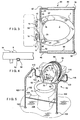
- Figure 1 is a perspective view illustrating the invention.
- Figure 2 is a side elevation view thereof.
- Figure 3 is a top plan view thereof.
- Figure 4 is a diagrammatic representation illustrating means for securing a user supporting frame to the toilet.
- Figure 5 is a perspective view illustrating another embodiment of the invention with added inventive features.
- Figure 6 is an isolated perspective view of a supporting frame.
- Figure 7 is a side elevation view of the embodiment shown in Figure 5.
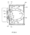
- Figure 8 is a top plan view thereof devoid of the seat and lid.
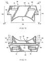
- Figure 9 is an isolated perspective view of a mounting block of the invention.
- Figure 10 is a top plan view of the mounting block taken through plane 10-10 of Figure 9.
- Figure 11 is a bottom plan view of the mounting block taken through plane 11-11 of Figure 9.
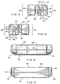
- Figure 12 is a side elevational view of the mounting block taken through plane 12-12 of Figure 9.
- Figure 13 is a side elevational view of the mounting block taken through plane 12-12 of Figure 9.
- Figure 14 is a front elevational view of the mounting block taken through line 14-14 of Figure 10.
- Figure 15 is a rear elevational view of the mounting block taken through line 15-15 of Figure 10.
- Figure 16 is a top plan view of the mounting block illustrating a single mounting slot.
- Figure 17 is a top plan view of the mounting block illustrating a pair of mounting slots at the mounting block side walls.
- Figure 18 is a top plan view of the mounting block illustrating two pairs of double mounting slots with each pair connected by a joining slot.
- a toilet 2 has a riser 3, a toilet lid 4 and a toilet seat 5.
- the lid 4 is mounted to the seat 5 in a conventional manner.
- a toilet seat height increasing apparatus 6 includes a mounting block 8 which directly and indirectly supports the riser 3, lid 4 and seat 5 to provide a raised toilet seat which is particularly advantageous for use by those who have difficulty in lowering and raising themselves from a conventional toilet seat, or need assistance in doing so, as will be appreciated.
- the mounting block 8 is formed with elongated through slots 10 and 12.
- the slots 10 and 12 are transverse relative to the front/rear orientation of toilet 2.
- Bolts or similar features 14 and 16 extend through the slots 10 and 12, respectively, and extend through holes provided at the rear of toilet 2 so as to be secured thereon via securing means 17 such as nuts as shown in Figure 2.
- Toilet seat 5 and mounting block 8 are thus secured to toilet 2 by upper and lower bolt fasteners 14 and 16.
- the seat 5 with the lid 4 are pivotably connected via a flange to the upper portions of bolts 14 and 16 and thus can pivot up and down toward and away from the toilet 2.
- the riser 3 rests on the bowl 7 of the toilet 2 as shown in Figure 3.
- the block 8 includes a pair of pin recesses or detents 18 and 20 on opposite sides thereof, respectively.
- the pin recesses or detents 18 and 20, as described in greater detail later on in the specification, are adapted to receive pins 22 and 24 on the riser 3, whereby the riser 3 pivots up and down away from and toward the toilet 2 in a similar manner.
- the lid 4 and the seat 5 pivot up and down away from and toward the riser 3.
- the front of the block 8 is contoured to match the contour of the riser 3, the lid 4 and the seat 5.
- the detents 18 and 20 are disposed in clearance steps 26 and 28 in the block 8.
- the height of the riser 3 corresponds to the height of the block 8.
- the elongated slots 10 and 12 are provided to accommodate a variation in the spacing of the holes 14 and 16 in the toilet 2 as may be the case particularly in countries other than the United States.
- the block 8 is also adapted to support a user supporting frame 30. This feature of the invention is important to those who might otherwise need assistance in using toilet 2 even with its height increasing apparatus.
- supporting the frame 30 includes a pair of substantially vertically extending parallel legs 32 and 34 having lower ends which rest on a supporting surface 36 through resilient tips 38, as the case may be.
- the legs 32 and 34 terminate at their upper ends in substantially horizontally extending parallel arms 40 and 42.
- the arms 40 and 42 and the upper parts of the legs 32 and 34 which are covered with a resilient tubing 44 and 46, respectively, for comfort purposes extend rearwardly to the back of the toilet 2 and thereupon terminate in substantially vertically and downwardly extending parallel members 48 and 50, respectively.
- the members 48 and 50 terminate in a substantially horizontal member 52.
- a brace 56 is supported between the lower portions of the legs 32 and 34.
- the frame 30 can be formed having independent first and second side components as well as an attaching component.
- the first component includes the leg 32, arm 40 and an upper part of the member 48.
- the second side component consists of the leg 34, arm 42 and an upper part of the member 50.
- the attaching component is formed by the horizontal member 52 and lower parts of the members 50 and 48 attached thereto.
- connecting arrangements or any conventional connecting means 45 and 47 are provided in the central regions of the members 48 and 50 correspondingly. Such arrangement facilitates assembly and transportation of the frame 30. It should be noted, however, that formation of the frame as a unitary structure without the connecting arrangements 45 and 47 is also contemplated.
- the underside of the block 8 includes a longitudinal channel 58.
- the channel 58 receives the member 52 of the supporting frame 30.
- frame member 52 is clamped in channel 58 so as to be held secure therein, whereby the entire frame 30 is secured to the block 8, when the bolts 14 and 16 are tightened to the toilet 2 via the nuts 17, as illustrated and described with reference to Figures 2 and 3.
- a riser which has the advantage of being able to utilize a conventional toilet so as to increase the height of the toilet seat for advantageous use by those who would otherwise have difficulty using same.
- FIG. 5 Another embodiment of a toilet seat height increasing apparatus 60 is illustrated in Figures 5, 7, and 8. Similar to the above-discussed embodiment, a conventional toilet 62 has a toilet seat 64 and a lid 66 is mounted to the seat 64 in a conventional manner. The toilet 62 has toilet front and rear portions 72 and 74, respectively.
- the toilet seat height increasing apparatus 60 includes a mounting block 68 and a U-shaped riser 70, which is supported by the mounting block 68.
- a pair of elongated slots 76 and 78 are formed in the mounting block 68 transversely oriented relative to the toilet front and rear portions 72 and 74 and which extend substantially vertically through the mounting block 68 in alignment with a pair of holes 80 and 82, respectively, that extend vertically through the toilet 62 at the toilet rear portion 74.
- the toilet seat 64 and the lid 66 are positioned upon the mounting block 68.
- Both the mounting block 68 and the toilet seat 64 are secured to toilet 62 at the toilet rear portion 74 by bolts 84 and 86 that extend through the slots 76 and 78 and the holes 80 and 82, respectively, and are conventionally secured at the underside and the topside of the toilet 62 by nuts at two flanges extending from two toilet seat pivots 89.
- the riser 70 during use rests upon a bowl 90 of the toilet 62 resulting in raising the effective height of the toilet seat 64.
- the riser 70 is pivotably mounted to the mounting block 68 at substantially cylindrical pins 92 and 94 that are positioned in pin recess or detents 96 and 98 that are formed in the mounting block 68 so that the riser 70 is pivotably mounted to the mounting block 68 and movable between raised and lowered riser positions relative to the toilet 62.
- the riser 70 can be positioned on the toilet 62 in the lowered position (shown as the riser 70A in phantom line in Figure 7) and can be positioned away from the toilet 62 in the raised position (see Figures 5 and 7).
- the toilet seat 64A is shown in phantom line optionally positioned on the riser 70A and the lid 66A shown in phantom line optionally positioned on the toilet seat 64A when the riser is in the lowered position.
- the mounting block 68 is positioned on and connected to the toilet 62 at the toilet rear portion 74.
- the toilet seat 64 and the lid 66 are pivotably mounted to the toilet 62 and are movable between a raised toilet seat/lid position where the toilet seat 64 and the lid 66 are pivoted to the generally vertical position as shown in Figures 5 and 7 and the lowered toilet seat/lid position where the toilet seat 64A is positioned upon the riser 70A with the lid 66A atop the seat 64A as shown in phantom line in Figure 7.
- transverse direction is defined as the direction from front to rear of the toilet, whereas lateral direction is the direction extending at an angle to the transverse direction.
- a support frame 100 is used to support a user who needs assistance while sitting and lowering, rising relative to the toilet 62 and the toilet seat 64.
- the frame 100 includes a pair of substantially vertical legs 102 having leg upper ends 104 and leg lower ends 106 resting upon a support surface 108 located at the front portion 72 of the toilet 62.
- a pair of substantially horizontal arms 110 having arm front and rear ends 112 and 114, respectively, extend laterally relative to the toilet front and rear portions 72 and 74 along the opposed sides of the toilet 62.
- the arm front ends 112 are connected to the leg upper ends 104 and the arm rear ends 114 terminating at the toilet rear portion 74.
- a pair of substantially vertical outer support members 116 have outer support member upper and lower ends 118 and 120, respectively, with the outer support member upper ends 118 being connected to the corresponding arm rear ends 114.
- a pair of substantially horizontal upper support members 122 extend transversely relative to the toilet rear portion 74 and have upper support member outer and inner ends 124 and 126, respectively.
- the upper support member outer ends 124 are connected to the corresponding outer support member ends 120.
- a pair of substantially vertical inner support members 128 have inner support member upper and lower ends 130 and 132, respectively.
- the inner support member upper ends 130 are connected to the corresponding upper support member inner ends 126.
- a substantially horizontal support member 134 has opposed side ends 136 that are connected to the corresponding inner support member lower ends 132.
- a horizontal brace 138 is connected to the legs 104.
- the legs 102, the arms 110, the outer support members 116, the upper support members 122, the vertical support members 128, and the transverse support member 134 are preferably cylindrical in configuration but can have other suitable configuration.
- the support frame 100 can be formed either as unitary or composite structure.
- each outer support member 116 is formed having upper and lower portions which are connected together by the connecting arrangement 117.
- the connecting arrangement can be any conventional means of connecting together these upper and lower portions.
- the support frame 100 is formed by independent first and second side components and the attaching component.
- Each side component includes corresponding leg 102 and arm 110 as well as an upper portion of the outer support member 116, whereas the attaching component consists of the pair of substantially horizontal upper support members 122, the inner support members 128 and the horizontal support member 134.
- the attaching component also includes the lower portions of the outer support members 116.
- the frame 100 is made of any material capable of bearing weight, such as metal, plastic, etc.
- a resilient tubing 140 encloses the upper portions of the legs 102 and the arms 110.
- a mounting block 68 best shown in Figure 9-18 includes opposed generally horizontal top and bottom faces or walls 142 and 144, respectively; opposed generally vertical block sides 146 and 148, respectively; and opposed generally vertical block front and rear sides 150 and 152, respectively.
- the block front side 150 defines a central curved portion 153 contoured to follow the contour of the toilet rear portion 74.
- the block bottom wall 144 is positioned upon the toilet rear portion 74.
- the block bottom wall 144 defines a longitudinal arcuate channel 154 extending substantially horizontally between the block sides 146 and 148 transverse relative to the orientation between the toilet front and rear potions 72 and 74 and defining openings at the block vertical sides 146 and 148.
- the substantially horizontal transverse support member 134 of the support frame 100 is received within the transverse channel 154 (See Figures 7 and 8). Such an arrangement secures the horizontal support member 134 and prevents transverse movement of the support frame 100 relative to the orientation of the toilet front portion 72 and the toilet rear portion 74 during use by patients or elderly persons.
- the longitudinal arcuate, transverse channel 154 receives the substantially horizontal member 52.
- the block sides 146 and 148 define a pair of side substantially vertical, lateral, arcuate channels 156 and 158 extending between the block top and bottom walls 142 and 144 defining openings coextensive with the side openings formed by the longitudinal, transverse channel 154.
- the substantially vertical inner support members 128 of the frame 100 are positioned in the vertical, lateral channels 156 and 158, so as to secure the vertical inner support members 128 and prevent lateral movement of the support frame 100 relative to the orientation of the toilet front portion 72 and the toilet rear portion 74.
- the mounting block can be also arranged without the side vertical channels, so the surfaces of the block sides are flat.
- This embodiment of the mounting block accommodates the support frame illustrated in Figures 1-4 which is formed without a step-like portion defined by the pair of vertical inner support members and the horizontal support member.
- the U-shaped riser 70 is made of a biasable material and includes opposed riser side members 160 and 162 and a curved joining portion 164 all configured to mate with the toilet seat 64.
- a part of each block side of the mounting block adjacent the front side 150 defines a step-like formation with mounting side members 171 and 175.
- the mounting side members 171 and 175 of the mounting block define generally cylindrical detent recess 96 and 98, respectively.
- the pins 92 and 94 extend transversely from the riser side members 160 and 162, respectively, and are engaged within the detent recesses 96 and 98, respectively. In this manner the riser 70 can be pivoted between the raised, lowered and vice versa riser positions described hereinbefore.
- the mounting side members 171 and 175 of the vertical sides 146 and 148 define channels 166 each including channel tapered surfaces 168 contiguous with opposed channel side walls 170.
- the block vertical sides 146 and 148 define opening 172 at the block bottom wall 144.
- the channels 166 extend from the openings 172 in the direction of the detent recesses 96 and 98.
- the pins 92 and 94 are initially positioned at the openings 172.
- the distance between the tapered surfaces 168 gradually increases from the block bottom wall 142 to the detent recess 96 and 98, so that during the mounting process, as the pins 92 and 94 of riser 70 are directed along the channels 166 over the tapered surfaces 168, the riser side members 160 and 162 of the U-shaped riser 70 are forced apart from a non-biased mode to an ever increasing biased mode.
- the riser side members 160 and 162 self-bias back from the biased mode to the unbiased mode, so that the pins 92 and 94 snap into the detent recesses 96 and 98 for engagement therein.
- the riser 70 is pivotably connected to the mounting block 68.
- the single elongated slot 174 extends substantially vertically through the mounting block 68.
- the single elongated slot 174 is capable of being aligned with a plurality of spacings between the preformed mounting holes 80 and 82 defined in the toilet 62. Therefore, during the assembly the connecting bolts 84 and 86 pass through the holes 80 and 82 and the single slot 174.
- FIG. 17 Another variation is a pair of elongated slots 176 shown in Figure 17 which extend transversely relative to the toilet front portion 72 and the toilet rear portion 74 orientation between the block vertical sides 146 and 148 and vertically through the mounting block 68.
- Each of the slots 176 extend to the block vertical sides 146 and 148 where the apertures 178 are defined.
- the slots 176 are capable of being aligned with a plurality of spacings of preformed the mounting holes 80 and 82 defined in the toilet 62 in preparation for the connecting bolts 84 and 86 passing through the holes 80 and 82 and the slots 176 including apertures 178.
- slots 76 and 78, the single slot 174, and the pair of slots 176 is a pair of elongated multiple slots 180 and 182.
- such multiple slots are double slots which are defined by the mounting block 68 extending transversely between the block vertical sides 146 and 148 and which extend transversely relative to the toilet front portion 72 and the toilet rear portion 74 orientation and vertically through the mounting block 68.
- Each of double slot 180 and 182 comprises a pair of substantially parallel slots 180A and 182A, respectively, joined at midpoint by short slots 180B and 182B, respectively.
- the double slots 180 and 182 are capable of being aligned with a plurality of spacings of the preformed mounting holes 80 and 82 defined in toilets in preparation for the connecting bolts 84 and 86 passing through the holes 82 and the single slot 170.
- the mounting block 68 and the riser 70 may be fabricated of a suitable plastic material suitably molded into the configuration required, while the toilet 62 may be of conventional porcelain. Moreover, the present invention provides apparatus by which a conventional toilet seat and lid may be utilized in a conventional manner.
Landscapes
- Health & Medical Sciences (AREA)
- Public Health (AREA)
- Epidemiology (AREA)
- General Health & Medical Sciences (AREA)
- Toilet Supplies (AREA)
Claims (20)
- Structure de conversion de hauteur d'une toilette appropriée à une utilisation en combinaison avec une toilette (2), ayant au moins une portion arrière associée à un cadre de support (30), ayant un membre de support substantiellement horizontal (52) et se prolongeant des deux côtés de la toilette, ladite structure comprenant :et caractérisé par la formation dudit bloc de montage avec un moyen de canal transversal continu (58), capable de fixer un membre de support substantiellement horizontal (52) d'un cadre de support, pour empêcher le mouvement transversal dudit cadre de support par rapport à la toilette dans les deux directions transversales.un bloc de montage (8) capable d'être positionné sur une portion arrière d'une toilette,un moyen de levage (3) capable d'augmenter la hauteur effective d'un siège de toiletté (5), ledit moyen de levage étant raccordé, de manière à pouvoir pivoter, audit bloc de montage pour pouvoir être déplacé entre les positions levée et abaissée dudit moyen de levage par rapport à la toilette,des moyens de connexion réglables (14,16), capables de fixer ledit bloc de montage à la portion arrière de la toilette,
- Structure de la revendication 1, caractérisée en ce que le bloc de montage (8) comprend des moyens de canal latéral (158) pour fixer une paire de membres de support internes substantiellement verticaux (128) d'un cadre de support (30), pour empêcher un mouvement latéral dudit cadre de support par rapport à la toilette.
- Structure selon la revendication 1, caractérisée en ce que ledit bloc de montage comprend en outre des parois de bloc supérieure et inférieure (142,144) opposées, ladite paroi de bloc inférieure étant positionnée sur la portion arrière de la toilette, ledit moyen de canal transversal formé à ladite paroi de bloc inférieure définissant un canal transversal substantiellement horizontal passant à travers le bloc de montage, ledit membre de support horizontal du cadre de support pouvant être positionné au sein du canal transversal substantiellement horizontal.
- Structure selon la revendication 3, caractérisée en ce que ledit bloc de montage comprend en outre des parois latérales de bloc opposées (148) et ledit moyen de canal latéral étant formé auxdites parois latérales de bloc opposées définissant une paire de canaux substantiellement verticaux en alignement avec les extrémités dudit canal transversal substantiellement horizontal, lesdits membres de support internes substantiellement verticaux pouvant être positionnés dans ladite paire de canaux substantiellement verticaux.
- Structure selon la revendication 4, caractérisée en ce que ledit moyen de connexion réglable est un arrangement à fentes (10,12), prévu pour être aligné avec des trous de montage préformés définis dans la toilette.
- Structure selon la revendication 1, caractérisée en ce que ledit bloc de montage comprend des membres latéraux opposés de montage (175), lesdits membres latéraux de montage définissant des cavités de détente opposées (96,98) et en ce que ledit moyen de levage comprend des parois latérales opposées de moyen de levage (171,175), ayant une paire de goupilles d'articulation (92,94), prévues pour pouvoir être alignées et pour pouvoir s'engager dans lesdites cavités de détente.
- Structure selon la revendication 6, caractérisée en ce que ledit moyen de levage est fait d'un matériau polarisable et en ce que lesdits membres latéraux de montage comprennent en outre des moyens à conicité (168) pour accepter initialement ladite paire de goupilles pendant le montage dudit moyen de levage audit bloc de montage et pour diriger lesdites goupilles vers lesdites cavités de détente, ledit moyen de levage pouvant être déplacé d'une mode non polarisé à un mode polarisé pendant le montage et étant auto-polarisé du mode polarisé au mode non polarisé après l'engagement au sein des cavités de détente.
- Structure selon la revendication 5, caractérisée en ce que ledit arrangement à fentes dans ledit bloc de montage définit une fente unique allongée, se prolongeant transversalement, qui se prolonge entre lesdites parois de bloc supérieure et inférieure et en général entre lesdites parois latérales de bloc, ladite fente unique allongée étant capable d'être alignée avec une pluralité d'écartements possibles des trous de montage préformés définis dans la toilette.
- Structure selon la revendication 5, caractérisée en ce que ledit arrangement à fentes dans ledit bloc de montage définit une paire de fentes allongées se prolongeant entre lesdites parois supérieure et inférieure et passant à travers lesdites parois latérales de bloc, de telle sorte que des ouvertures soient définies aux jonctions desdites parois latérales de bloc avec lesdites fentes allongées, en facilitant la fixation du bloc à la toilette.
- Structure selon la revendication 5, caractérisée en ce que ledit arrangement à fentes dans ledit bloc de montage définit une paire de combinaisons à fentes allongées se prolongeant transversalement (180,182), qui se prolongent entre lesdites parois supérieure et inférieure et en général entre lesdites parois latérales de bloc, chaque dite combinaison à fentes comprenant au moins deux fentes allongées appariées se prolongeant transversalement (180A,182A) et une fente latérale (180B,182B) pour joindre lesdites deux fentes appariées.
- Structure de conversion de hauteur d'une toilette selon la revendication 1, appropriée à une utilisation en combinaison avec un cadre, comprenant au moins un membre de support substantiellement horizontal et une paire de membres de support internes substantiellement verticaux (128), ladite structure comprenant en outre :des moyens de canal latéral (158) associés audit bloc de montage (8), capables de fixer ladite paire de membres de support internes verticaux, pour empêcher un mouvement latéral dudit moyen de cadre par rapport à la toilette.
- Structure selon la revendication 11, caractérisée en ce que ledit bloc de montage comprend des parois de bloc supérieure et inférieure (142,144) opposées, ladite paroi de bloc inférieure pouvant être positionnée.sur la portion arrière de la toilette, en ce que ledit moyen de canal transversal est un canal substantiellement horizontal défini à ladite surface de bloc inférieure, ledit membre de support horizontal pouvant être positionné au sein dudit canal substantiellement horizontal.
- Structure selon la revendication 12, caractérisée en ce que ledit moyen de canal latéral est une paire de canaux substantiellement verticaux, en ce que ledit bloc de montage comprend en outre des parois latérales de bloc opposées (148), définissant lesdits canaux substantiellement verticaux en alignement avec ledit canal substantiellement horizontal, lesdits membres de support internes verticaux pouvant être positionnés dans lesdits canaux substantiellement verticaux.
- Appareillage d'augmentation de la hauteur d'un siège de toilette, approprié à une utilisation en combinaison avec un siège de toilette existant (5), un couvercle (4) et un moyen de montage comprenant :un bloc de montage (8) ayant des surfaces supérieure et inférieure définissant une hauteur prédéterminée ;un moyen de levage (3) monté, de manière à pouvoir être pivoté, au bloc de montage de manière à pouvoir être levé et abaissé par rapport à une toilette ;le bloc de montage permettant à un siège de toilette d'être monté au bloc de manière à pouvoir être levé et abaissé par rapport à la toilette ;ledit bloc de montage comprenant des trous espacés longitudinalement (10,12) s'y prolongeant, le bloc de montage pouvant être monté à la surface arrière supérieure d'une toilette par le biais de moyens de montage, en utilisant les trous prévus dans ladite toilette pour monter le moyen de levage qui est substantiellement de la même hauteur que le bloc de montage ; et caractérisé en comprenant en outre :un cadre (100) pour supporter un utilisateur ;ledit cadre de support d'utilisateur comprenant une paire de jambes substantiellement parallèles, se prolongeant substantiellement verticalement (102), supportées aux extrémités inférieures sur une surface de support (108) ;des moyens (110) de connexion desdites jambes à un membre substantiellement horizontal (122) en alignement avec la surface inférieure (144) du bloc de montage ;ladite surface inférieure du bloc de montage comprenant un canal (154) qui reçoit ledit membre substantiellement horizontal du cadre de support ; etledit membre horizontal et ledit cadre de support étant fixés de manière sûre par ledit bloc de montage quand ledit bloc de montage est monté sur la surface arrière supérieure de la toilette par le biais desdits moyens de montage.
- Appareillage d'augmentation de la hauteur d'un siège de toilette selon la revendication 14, caractérisé en ce que
les trous espacés longitudinalement sont allongés longitudinalement pour accommoder une variation dans l'écartement des trous. - Appareillage d'augmentation de la hauteur d'un siège de toilette selon la revendication 14 ou 15, caractérisé en ce que le moyen de connexion des jambes à un membre substantiellement horizontal en alignement avec la surface inférieure du bloc de montage comprend :les jambes se terminant à leurs extrémités supérieures en bras parallèles se prolongeant substantiellement horizontalement ;lesdits bras parallèles se prolongeant vers l'arrière jusqu'à l'arrière de la toilette et se terminant par des membres parallèles se prolongeant substantiellement verticalement et vers le bas (116) ; etlesdits membres se prolongeant vers le bas se terminant sur des côtés opposés dudit membre substantiellement horizontal.
- Appareillage d'augmentation de la hauteur d'un siège de toilette selon l'une quelconque des revendications 14 à 16, caractérisé en ce que
le cadre de support est un membre autonome. - Appareillage d'augmentation de la hauteur d'un siège de toilette, selon la revendication 16 ou 17, caractérisé en ce que
les parties supérieures des jambes et au moins une partie des bras parallèles se prolongeant substantiellement horizontalement étant recouvertes par des moyens améliorant le confort d'un utilisateur du siège de toilette. - Appareillage d'augmentation de la hauteur d'un siège de toilette selon l'une quelconque des revendications 14 à 18, caractérisé en ce que
le bloc de montage comprenant des cavités alignées sur ses côtés opposés ;
le moyen de levage comprenant des goupilles sur ses côtés opposés alignés en alignement avec les cavités alignées ; et
les goupilles s'engageant dans les cavités correspondantes de manière à permettre le montage de manière pivotante, du moyen de levage au bloc de montage. - Structure de conversion de la hauteur d'une toilette selon l'une quelconque des revendications 1 à 13, caractérisée en ce que
le bloc de montage comprenant des cavités alignées sur ses côtés opposés ;
le moyen de levage comprenant des goupilles sur ses côtés opposés en alignement avec les cavités alignées ; et
les goupilles s'engageant dans les cavités correspondantes de manière à permettre le montage de manière pivotante du moyen de levage au bloc de montage.
Applications Claiming Priority (6)
| Application Number | Priority Date | Filing Date | Title |
|---|---|---|---|
| US754796 | 1985-07-12 | ||
| US566933 | 1990-08-13 | ||
| US56693395A | 1995-12-04 | 1995-12-04 | |
| EP96301234A EP0777994A1 (fr) | 1995-12-04 | 1996-02-23 | Siège de toilettes avec surélévateur |
| EP96301234 | 1996-02-23 | ||
| US08/754,796 US5920917A (en) | 1995-12-04 | 1996-11-21 | Toilet seat including height increasing apparatus |
Publications (2)
| Publication Number | Publication Date |
|---|---|
| EP0777995A1 EP0777995A1 (fr) | 1997-06-11 |
| EP0777995B1 true EP0777995B1 (fr) | 2002-05-08 |
Family
ID=27237671
Family Applications (1)
| Application Number | Title | Priority Date | Filing Date |
|---|---|---|---|
| EP19960308614 Expired - Lifetime EP0777995B1 (fr) | 1995-12-04 | 1996-11-28 | Surélévateur de siège de toilettes |
Country Status (2)
| Country | Link |
|---|---|
| EP (1) | EP0777995B1 (fr) |
| DE (1) | DE69621109T2 (fr) |
Cited By (1)
| Publication number | Priority date | Publication date | Assignee | Title |
|---|---|---|---|---|
| DE102004020394A1 (de) * | 2004-04-23 | 2005-11-10 | Aquatec Gmbh & Co. Kg | Vorrichtung zur Erhöhung der Sitzhöhe auf einem Klosett |
Families Citing this family (2)
| Publication number | Priority date | Publication date | Assignee | Title |
|---|---|---|---|---|
| AUPQ252599A0 (en) * | 1999-08-27 | 1999-09-23 | Dominguez, Peter Robert | Toilet support |
| BRPI0503415C4 (pt) * | 2005-07-25 | 2009-10-27 | Flavio Pereira Del Arroyo Antonio | disposição construtiva de acessório para apoio e do es |
Family Cites Families (5)
| Publication number | Priority date | Publication date | Assignee | Title |
|---|---|---|---|---|
| US3405411A (en) * | 1966-09-01 | 1968-10-15 | Beneke Corp | Arm and seat assembly |
| FR2336906A1 (fr) * | 1975-12-31 | 1977-07-29 | Ayrolles Francois | Dispositif a accoudoirs destines a equiper les sieges de certains appareils sanitaires |
| US4477932A (en) | 1984-02-10 | 1984-10-23 | Maddak, Inc. | Raised superimposed toilet seat and securing clamp |
| GB2177735B (en) * | 1985-07-09 | 1988-05-11 | James Ind Ltd | Toilet aids |
| US5251338A (en) | 1991-07-23 | 1993-10-12 | Light Homer E | Toilet height conversion apparatus |
-
1996
- 1996-11-28 EP EP19960308614 patent/EP0777995B1/fr not_active Expired - Lifetime
- 1996-11-28 DE DE1996621109 patent/DE69621109T2/de not_active Expired - Fee Related
Cited By (1)
| Publication number | Priority date | Publication date | Assignee | Title |
|---|---|---|---|---|
| DE102004020394A1 (de) * | 2004-04-23 | 2005-11-10 | Aquatec Gmbh & Co. Kg | Vorrichtung zur Erhöhung der Sitzhöhe auf einem Klosett |
Also Published As
| Publication number | Publication date |
|---|---|
| DE69621109D1 (de) | 2002-06-13 |
| EP0777995A1 (fr) | 1997-06-11 |
| DE69621109T2 (de) | 2002-12-12 |
Similar Documents
| Publication | Publication Date | Title |
|---|---|---|
| US5920917A (en) | Toilet seat including height increasing apparatus | |
| CA2458152C (fr) | Poignee auxiliaire pour lits | |
| US4715069A (en) | Toilet aids | |
| US5582464A (en) | Chair primarily for use by persons with spinal chord injury | |
| US5526537A (en) | Portable chair commode | |
| US8336898B2 (en) | Reconfigurable tilt wheelchair | |
| US5056863A (en) | Laterally adjustable armrest for a chair | |
| US4629246A (en) | Wheelchair seat | |
| EP0153507B1 (fr) | Siège de toilette surélevé et superpositionné et agrafe de fixation | |
| US5251338A (en) | Toilet height conversion apparatus | |
| US4861108A (en) | Auditorium seat | |
| US5708989A (en) | Toilet seat assemblies | |
| MXPA97006171A (en) | Seat writing assembled maneraestaciona | |
| EP0145028B1 (fr) | Siège de cabinet surélevé | |
| EP1060723A2 (fr) | Cadre latéral réglable et fauteuil roulant avec cadre latéral réglable | |
| US5027445A (en) | Raised superimposed toilet seat and securing clamp | |
| EP0607362A1 (fr) | Dispositif pour siege de cabinet de toilette | |
| US20090013453A1 (en) | Toilet seat elevator assembly | |
| EP0777995A1 (fr) | Siège de toilettes avec surélévateur | |
| JPH02193728A (ja) | 公共輸送車両用座席支持具及びこれを備えた座席 | |
| GB2237735A (en) | Frame | |
| JP2597193Y2 (ja) | 観覧席用椅子の脚 | |
| CN222870379U (zh) | 一种新型儿童阶梯马桶架结构 | |
| KR102251796B1 (ko) | 의자의 팔걸이 구조 | |
| JP2527768Y2 (ja) | 椅 子 |
Legal Events
| Date | Code | Title | Description |
|---|---|---|---|
| PUAI | Public reference made under article 153(3) epc to a published international application that has entered the european phase |
Free format text: ORIGINAL CODE: 0009012 |
|
| AK | Designated contracting states |
Kind code of ref document: A1 Designated state(s): DE GB SE |
|
| 17P | Request for examination filed |
Effective date: 19971004 |
|
| 17Q | First examination report despatched |
Effective date: 19990416 |
|
| RTI1 | Title (correction) |
Free format text: TOILET HEIGHT INCREASING APPARATUS |
|
| RTI1 | Title (correction) |
Free format text: TOILET HEIGHT INCREASING APPARATUS |
|
| GRAG | Despatch of communication of intention to grant |
Free format text: ORIGINAL CODE: EPIDOS AGRA |
|
| GRAG | Despatch of communication of intention to grant |
Free format text: ORIGINAL CODE: EPIDOS AGRA |
|
| GRAH | Despatch of communication of intention to grant a patent |
Free format text: ORIGINAL CODE: EPIDOS IGRA |
|
| REG | Reference to a national code |
Ref country code: GB Ref legal event code: IF02 |
|
| GRAH | Despatch of communication of intention to grant a patent |
Free format text: ORIGINAL CODE: EPIDOS IGRA |
|
| GRAA | (expected) grant |
Free format text: ORIGINAL CODE: 0009210 |
|
| AK | Designated contracting states |
Kind code of ref document: B1 Designated state(s): DE GB SE |
|
| REF | Corresponds to: |
Ref document number: 69621109 Country of ref document: DE Date of ref document: 20020613 |
|
| PLBE | No opposition filed within time limit |
Free format text: ORIGINAL CODE: 0009261 |
|
| STAA | Information on the status of an ep patent application or granted ep patent |
Free format text: STATUS: NO OPPOSITION FILED WITHIN TIME LIMIT |
|
| 26N | No opposition filed |
Effective date: 20030211 |
|
| PGFP | Annual fee paid to national office [announced via postgrant information from national office to epo] |
Ref country code: GB Payment date: 20061122 Year of fee payment: 11 |
|
| PGFP | Annual fee paid to national office [announced via postgrant information from national office to epo] |
Ref country code: DE Payment date: 20061214 Year of fee payment: 11 |
|
| PGFP | Annual fee paid to national office [announced via postgrant information from national office to epo] |
Ref country code: SE Payment date: 20061220 Year of fee payment: 11 |
|
| EUG | Se: european patent has lapsed | ||
| GBPC | Gb: european patent ceased through non-payment of renewal fee |
Effective date: 20071128 |
|
| PG25 | Lapsed in a contracting state [announced via postgrant information from national office to epo] |
Ref country code: SE Free format text: LAPSE BECAUSE OF NON-PAYMENT OF DUE FEES Effective date: 20071129 Ref country code: DE Free format text: LAPSE BECAUSE OF NON-PAYMENT OF DUE FEES Effective date: 20080603 |
|
| PG25 | Lapsed in a contracting state [announced via postgrant information from national office to epo] |
Ref country code: GB Free format text: LAPSE BECAUSE OF NON-PAYMENT OF DUE FEES Effective date: 20071128 |