EP0778110A2 - Procédé pour la modification du mode de fonctionnement d'un mécanisme de percussion actionné par un fluide et mécanisme de percussion pour la mise en oeuvre du procédé - Google Patents
Procédé pour la modification du mode de fonctionnement d'un mécanisme de percussion actionné par un fluide et mécanisme de percussion pour la mise en oeuvre du procédé Download PDFInfo
- Publication number
- EP0778110A2 EP0778110A2 EP96119281A EP96119281A EP0778110A2 EP 0778110 A2 EP0778110 A2 EP 0778110A2 EP 96119281 A EP96119281 A EP 96119281A EP 96119281 A EP96119281 A EP 96119281A EP 0778110 A2 EP0778110 A2 EP 0778110A2
- Authority
- EP
- European Patent Office
- Prior art keywords
- line
- control
- pressure
- piston
- time
- Prior art date
- Legal status (The legal status is an assumption and is not a legal conclusion. Google has not performed a legal analysis and makes no representation as to the accuracy of the status listed.)
- Withdrawn
Links
- 230000007246 mechanism Effects 0.000 title claims abstract description 35
- 238000000034 method Methods 0.000 title claims abstract description 25
- 238000009527 percussion Methods 0.000 title claims description 115
- 239000012530 fluid Substances 0.000 title description 6
- 239000000463 material Substances 0.000 claims abstract description 44
- 230000001419 dependent effect Effects 0.000 claims abstract description 13
- 230000000903 blocking effect Effects 0.000 claims description 12
- 230000009471 action Effects 0.000 claims description 11
- 230000000694 effects Effects 0.000 claims description 7
- 230000001960 triggered effect Effects 0.000 claims description 4
- 230000036962 time dependent Effects 0.000 claims description 3
- 230000008569 process Effects 0.000 abstract description 4
- 238000010586 diagram Methods 0.000 description 17
- 230000008859 change Effects 0.000 description 6
- 239000007779 soft material Substances 0.000 description 6
- 230000007423 decrease Effects 0.000 description 5
- 230000006378 damage Effects 0.000 description 4
- 230000003247 decreasing effect Effects 0.000 description 4
- 230000036961 partial effect Effects 0.000 description 4
- 238000006073 displacement reaction Methods 0.000 description 3
- 230000008901 benefit Effects 0.000 description 2
- 230000001934 delay Effects 0.000 description 2
- 238000003754 machining Methods 0.000 description 2
- 238000002310 reflectometry Methods 0.000 description 2
- 239000011435 rock Substances 0.000 description 2
- 206010027336 Menstruation delayed Diseases 0.000 description 1
- 230000004323 axial length Effects 0.000 description 1
- 238000010276 construction Methods 0.000 description 1
- 230000008030 elimination Effects 0.000 description 1
- 238000003379 elimination reaction Methods 0.000 description 1
- 230000003116 impacting effect Effects 0.000 description 1
- 230000000977 initiatory effect Effects 0.000 description 1
- 230000036316 preload Effects 0.000 description 1
- 230000002028 premature Effects 0.000 description 1
- 238000005086 pumping Methods 0.000 description 1
- 230000009467 reduction Effects 0.000 description 1
- 238000004904 shortening Methods 0.000 description 1
Images








Classifications
-
- B—PERFORMING OPERATIONS; TRANSPORTING
- B25—HAND TOOLS; PORTABLE POWER-DRIVEN TOOLS; MANIPULATORS
- B25D—PERCUSSIVE TOOLS
- B25D9/00—Portable percussive tools with fluid-pressure drive, i.e. driven directly by fluids, e.g. having several percussive tool bits operated simultaneously
- B25D9/14—Control devices for the reciprocating piston
- B25D9/26—Control devices for adjusting the stroke of the piston or the force or frequency of impact thereof
-
- B—PERFORMING OPERATIONS; TRANSPORTING
- B25—HAND TOOLS; PORTABLE POWER-DRIVEN TOOLS; MANIPULATORS
- B25D—PERCUSSIVE TOOLS
- B25D9/00—Portable percussive tools with fluid-pressure drive, i.e. driven directly by fluids, e.g. having several percussive tool bits operated simultaneously
- B25D9/14—Control devices for the reciprocating piston
- B25D9/145—Control devices for the reciprocating piston for hydraulically actuated hammers having an accumulator
Definitions
- the invention relates to a method for influencing the operating behavior of a percussion mechanism with a percussion piston, which alternately executes a working stroke in the direction of impact and a return stroke when acted upon by a fluid drive means under the influence of a control, a trigger signal being generated during the working stroke depending on the stroke of the percussion piston at an initial time T1 is, which initiates the switchover of the control to the return stroke position, and wherein the control reaches the return stroke position with an almost constant time delay ⁇ t1 for all stroke cycles at an end time T2 which is after completion of the working stroke.
- the invention further relates to a fluid-operated percussion mechanism suitable for carrying out the method, with a percussion piston movable in a working cylinder and striking a tool, and a control with a control slide movable in a control valve, the percussion piston having two piston surfaces of different sizes, one of which the smaller piston area acting in the direction of the return stroke is constantly connected to a pressure line under working pressure and the larger piston area acting in the direction of the working stroke is alternately connected to the pressure line and a pressure-free return line via the control valve, and the control slide being two different sizes, in relation to one another opposite direction of movement has effective slide surfaces, the smaller, in the direction of the return stroke position of the Control spool on this acting slide surface constantly with the pressure line and its larger slide surface as a control surface by means of a control line via a circumferential groove arranged between the piston surfaces is only temporarily and alternately connected to the pressure or the return line.
- a method and a fluid-operated hammer mechanism of the type mentioned at the outset are known from the document DE-C2-34 43 542.
- a special holding or change-over valve which is built into the control line that interacts with the control and is alternately connected to the return line, it should be ensured that this reflected energy is reflected even when the impact energy is reflected by the tool on the percussion piston is recovered hydraulically, whereby an increase in the number of percussion pistons is achieved.
- Fluid-powered striking mechanisms such as hydraulic hammers in particular, are used for material crushing (rock or concrete crushing). This comminution is achieved in that the kinetic energy of a percussion piston is introduced into the material to be processed by impacting it on a tool, via the tool tip, and is converted there into work of destruction. Depending on the hardness of the material to be processed, only part of the kinetic energy is converted into work of destruction; the energy component that is not converted is reflected by the tool in the percussion piston and can be used with an appropriate device to increase the number of blows. In contrast, with softer material, the impact energy is completely converted into work of destruction.
- the purpose of the present invention is to change the impact force in such a way that it enables material to be comminuted without the fluid flow rate required to accelerate the impact piston to change significantly.
- the invention is accordingly based on the object of providing a method and a percussion mechanism suitable for carrying out the method, with which the percussion force of the percussion piston can be adapted automatically and in a reflection-dependent manner to the material hardness.
- the task is basically solved in that the percussion piston stroke is adapted to the hardness of the material to be processed, utilizing the hydraulic energy recovered during reflections.
- the method for influencing the operating behavior consists in the core, in addition to the first time delay - which the control system requires for switching from the working stroke position to the return stroke position - to start a second time delay which varies with the operating pressure, with the result that the percussion piston first executes a return stroke depending on the reflectance of the material to be processed and - after switching the control to the return stroke position - a residual return stroke, which increases with increasing size of the reflectance changing the operating pressure, at the end time the second Time delay regardless of the percussion piston position the switching of the control is initiated in the working stroke position.
- the second time delay can be triggered directly or indirectly by the percussion piston.
- the trigger signal generated by the percussion piston which initiates the switchover of the control system to the percussion piston return stroke position, to activate a circuit (via an additional timer) which, in turn, after a predetermined period of time has the already mentioned second time delay in Run sets.
- This can be adjusted to adapt to different working conditions and - as long as the setting value is not changed - depends on the degree of reflection (and thus on the material hardness).
- the percussion piston has at most made a very small return stroke after the first time delay; accordingly, the total return stroke traveled until the control system is switched to the working stroke position will be correspondingly small, with the result that the subsequent working stroke will also be correspondingly small and the impact energy will therefore have a correspondingly smaller value.
- the then returning percussion piston executes a relatively large return stroke during the first time delay, which is felt during the second time delay until the control is switched to the working stroke position the residual return stroke forced by the drive connects.
- the impact on hard material therefore has the consequence that the percussion piston carries out a comparatively larger return stroke and the subsequent work process with a correspondingly high impact force within the time available - which is dependent on the size of the reflectance.
- the impact piston only ejects hydraulic fluid into the return line of the impact mechanism during the remaining return stroke. Since the volume flow balance at the striking mechanism is balanced, a lower residual return stroke height means a higher number of strokes for a given volume flow.
- the second time delay can either be triggered directly by a trigger signal from the percussion piston (i.e. depending on the path) or only indirectly from the percussion piston, i.e. be set in motion regardless of the route.
- the method can be carried out particularly simply if care is taken to ensure that the start time of the second time delay coincides with the end time of the first time delay (claim 2).
- the second delay time should be selected so that the switchover at the associated end time is initiated in such a way that the striking piston is below the greatest possible reflectance (even) at a certain reflectance of the material to be processed. executes the design maximum return stroke (claim 3).
- the method is expediently carried out in such a way that the second time delay is interrupted in good time, depending on the stroke of the percussion piston, by means of a limit switch; this ensures that the switchover of the control to the working stroke position is completed at the latest when the percussion piston has reached the upper reversal point specified in the design (claim 4).
- the second delay time can also be selected so that the percussion piston reaches the structurally predetermined upper reversal point with the greatest possible degree of reflection of the material to be processed (claim 5).
- the method can be carried out in such a way that by adjusting the second delay time it is ensured that the percussion piston always performs a predetermined minimum return stroke. Its value can be in particular between 20 and 50% of the maximum return stroke provided by the design (claim 7).
- the core idea of the invention consists in the use of a time-delay switching pilot valve, which (in the normal case) brings about the switchover of the control from the return stroke position to the working stroke position.
- the larger, in the direction of the working stroke position effective slide area of the control is connected via an additional line to the output of a pilot valve provided with a reset, which can be transferred from its open to the blocked position by the effect of the reset, whereby the the Resetting counteracting adjustment force is caused by the fact that the working pressure applied to the larger piston surface of the percussion piston acts on a control surface of the pilot valve via a pilot line.
- This is assigned a delay element, under the effect of which the pilot valve switches with a delayed period of time from the blocking position into the open position.
- the latter is either permanently and directly connected on the inlet side or - depending on the position of the percussion piston within the working cylinder - is only temporarily connected to the pressure line via the front cylinder space section delimited by the smaller piston area (claim 8).
- the pilot valve only moves from the blocking to the open position after an adjustable period of time under the action of the delay element and only then - if necessary depending on the position of the percussion piston within the working cylinder - conducts the changeover of the control spool in the working stroke position.
- the control itself operates with a time delay insofar as its control spool requires a system-specific time period for the movement from the return stroke position to the working stroke position and vice versa.
- the delay element can be designed as desired, taking into account the requirements to be placed on it.
- the delay element preferably consists of a current regulator, the setpoint of which can be adjusted as a function of pressure and which is connected directly or indirectly via the reversing line emanating from the control for the application of the larger piston area to the return line (claim 9).
- the current regulator By means of the current regulator, the flowing through can Adjust the volume flow to a set setpoint as long as there is no pressure change that changes the setting.
- the spring height of the percussion piston changes and with it the system pressure.
- the current controller then adjusts to a new, system pressure-dependent setpoint, whereby the remaining return stroke of the percussion piston is determined or changed.
- the current regulator is normally designed in such a way that its flow cross-section is completely open if it is flowed through in the opposite direction, that is to say its outlet is subjected to the higher pressure. If the pressure in the changeover line drops, the pilot valve can switch from the initially assumed blocking position to the open position under the action of the reset and counter to the effect of the flow controller, and can thus apply working pressure to the larger slide area of the control.
- the striking mechanism can also advantageously be further developed in that a check valve is connected in parallel to the flow controller in the direction of the pilot valve, which takes the closed position, while the pilot valve switches from its blocking to the open position (claim 10).
- the check valve not only enables faster filling of the pilot line; it also ensures that the pilot valve may be moved to its blocking position more quickly than under the influence of the flow regulator alone. Accordingly, by using the check valve in addition - which, if necessary, can also be spring-loaded - greater overall delay times can be achieved.
- pilot valve in the direction of the open position
- the pilot valve being constantly connected to the pressure line via a smaller adjusting surface (which is opposite to the larger adjusting surface connected to the pilot line).
- the input line connected to the pilot valve on the input side can - seen in the longitudinal direction of the percussion piston - be arranged between the confluence of the pressure line in the front cylinder chamber section and the confluence of the control line in the cylinder chamber in such a way that its confluence with the cylinder chamber is closed by the percussion piston at the time of impact of the percussion piston (Claim 11).
- the confluence of the input line or the control line in the cylinder chamber represents a short-stroke or long-stroke bore. Via this short-stroke bore, the input line of the pilot valve is only subjected to the working pressure after the percussion piston has covered a certain distance during its return stroke.
- the striking mechanism can be further configured in that the additional line is equipped with a shuttle valve, which is connected to the return line at the same time (claim 12).
- the shuttle valve - its structure and mode of operation in the already mentioned publication DE-C2-34 43 542 ensures, among other things, that the movement of the control spool in the return stroke position, regardless of the position of the percussion piston within the cylinder space, is not hindered.
- the embodiment according to claim 13, in which the current regulator connected in parallel with the check valve with respect to the pilot line is continuously connected to the return line, has the advantage that the delay time caused by the current regulator is essentially independent of the pressure conditions in the changeover line for the larger piston area .
- the pressure build-up in this changeover line can - depending on the operating conditions - proceed more or less quickly and would therefore influence the second time delay if the current controller were directly connected to the changeover line.
- the pilot valve is in A hydraulically or mechanically generated restoring force is applied to the opening direction.
- the pilot valve In the closing direction, the pilot valve is pressurized with the working pressure (system pressure) via an adjusting orifice with a fixed cross-section and, in addition, with a fixed pressure via a control line.
- the restoring force already mentioned in the opening direction can be generated in particular by means of a pressure reducing valve. Instead, the restoring force can also be triggered mechanically by means of a restoring spring.
- Fig. 1a, b show that the period T for the working cycle of the percussion piston of a hydraulic percussion mechanism becomes shorter with increasing hardness of the material to be processed if the percussion piston stroke S is set constant; this is the case when using controls which are usually designed to work depending on the piston travel.
- the differently long time period T of a work cycle results from the distance between the two adjacent times at which the percussion piston has reached the top dead center OT (or also the top reversal point).
- the impact point AP indicates that the percussion piston hits the tool - usually a chisel - at the specified time.
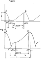
- the control of the striking mechanism requires a period of time ⁇ t1 (with the start time T1 and end time T2) or a time period ⁇ t3 with the start time T4 for switching from the working stroke position to the return stroke position on the one hand and from this to the working stroke position on the other hand.
- the switchover of the control from the working stroke position to the return stroke position is usually initiated by a trigger signal which is caused in time before the time of impact AP.
- the impact piston - since no impact energy is reflected - does practically no movement for a short time after hitting the tool, i.e. the return stroke movement of the percussion piston is only brought about after the control has switched to the return stroke position at time T2. Accordingly, a relatively large period of time is required for the return stroke for a given size S.
- the partial return of the percussion piston in the return stroke direction has the result that part of the impact energy is recovered (by the hydraulic piston pumping hydraulic fluid into a storage medium via the larger piston area) and the time required for the execution of the remaining return stroke is relatively short. Accordingly, the use of a path-dependent control means that the impact rate of the percussion piston is higher when processing hard material than when processing soft material.
- Fig. 1c in connection with Fig. 1d shows that when kept constant Percussion piston stroke S the number of strokes z increases with increasing size of the reflectance R.
- the procedure within the scope of the invention is such that the distance S traveled by the percussion piston is shortened or lengthened depending on the material by changing the time duration for the total return stroke.
- a second time delay .DELTA.t2 which is dependent on the degree of reflection, is started (FIG. 2a, b), after its expiration (end time T4) the switchover of the control unit from the return stroke is initiated in the working position (time period ⁇ t3): the initiation of the switchover at the end time T4 is therefore only time-dependent and accordingly independent of the percussion piston path S covered at this time.
- the start time T3 of the second time delay ⁇ t2 can be determined at any time by a suitable trigger signal. In the embodiment shown in FIGS. 2a, b, the start time T3 coincides with the end time T2 of the first time delay ⁇ t1.
- Fig. 2a shows that the path S of the percussion piston in the case of processing soft material is only about half as large as shown in Fig. 1a. This means that the impact force has been considerably reduced compared to the embodiment according to FIG. 1a and only the impact force required for the destruction of the soft material is generated; however, the number of blows remained at a similarly high level as in the case of processing hard material due to the shorter duration T of the working cycle.
- the second time delay .DELTA.t2 (H) has been dimensioned such that when machining hard material the constructively provided maximum return stroke is reached:
- the path S between the top dead center OT and the impact point AP is the same.
- the time delay ⁇ t2 (H) is greater than that for soft material ( ⁇ t2 (W) in Fig. 2a).
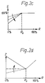
- the percussion piston travel S - as can be seen from FIG. 2c - can in particular also be changed such that it rises to a lower limit value R 0 and then remains constant through a limit switch.
- the associated course of the beat number z as a function of the reflectance R is shown in FIG. 2d.
- the fluid volume conveyed back when the percussion piston springs back is absorbed in a manner known per se by a storage means and is reactivated in the subsequent working stroke.
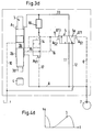
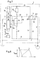
- the striking mechanism 1 (cf. FIG. 3a) has, in addition to the lines to be described as well as drive and control elements, a working cylinder 2 in which a percussion piston 3 is held in a longitudinally movable manner.
- This has two piston collars 3a, 3b lying in the interior of the working cylinder, which are separated from one another by a circumferential groove 3c.
- the outwardly directed piston surface A1 and A2 of the piston collar 3a or 3b delimits a rear and front cylinder space section 2a or 2b with the working cylinder.
- the percussion piston 3 merges into a piston tip 3d, which is opposite a tool in the form of a chisel 4.
- the piston area A2 is dimensioned smaller than the piston area A1.
- FIG. 3a shows the striking mechanism in a state immediately after the striking piston 3 hits the chisel 4; the associated percussion piston position is indicated by a circle in the path-time diagram according to FIG. 4a.
- the control for switching over the movement of the percussion piston 3 consists of a control slide 5a movable in a control valve 5, the smaller slide area A S1 of which is constantly acted upon by the working pressure via a return line 6; this is generated by an energy source in the form of a hydraulic pump 7.
- the smaller piston area A2 is also constantly subjected to the working pressure via a pressure line 8, which is connected to the return line 6.
- the opening 8a of the pressure line is arranged with respect to the working cylinder in such a way that it is in any case outside the piston collar 3b and thus inside the front cylinder space section 2b.
- the larger slide area A S2 of the control slide 5a is connected via a control line 9 to the cylinder space in such a way that its mouth 9a in the state shown is connected via the circumferential groove 3c to a return line 10 which is kept pressureless.
- the mouth 9a and the mouth 10a of the return line are thus - seen in the longitudinal direction of the percussion piston 3 - at a distance which is smaller than the axial length of the circumferential groove 3c.
- the control valve 5 is connected on the one hand via a line 11 to the pressure line 8 and on the other hand via a line 12 to the return line 10. On the other hand, the control valve 5 is connected via a changeover line 13 to the rear cylinder chamber section 2a, via which the larger piston area A1 can be acted upon if necessary.
- the control valve 5 can assume two valve positions, namely the illustrated (left) working stroke position, in which the larger piston area A1 is acted upon by the reversing line 13 and the line 11 with the working pressure, and the (right) return stroke position, in which the rear cylinder chamber section 2a the changeover line 13, the line 12 and the return line 10 are kept depressurized.
- the striking mechanism 1 is additionally equipped with a pilot valve 14 which is connected to the cylinder chamber on the one hand via an input line 15 and on the other hand to the control line 9 via an additional line 16.
- the pilot valve 14 is designed in such a way that it can either assume the blocking position shown or an open position in which the lines 15 and 16 are connected to one another.
- the mouth 15a of the input line into the cylinder chamber is arranged such that - seen in the longitudinal direction of the percussion piston 3 - it lies between the orifices 8a and 9a and is closed by the piston collar 3b in the illustrated impact position of the percussion piston.
- the position of the pilot valve 14 can be influenced via two surfaces, namely via the smaller resetting surface A V1 and the larger adjusting surface A V2 .
- the first-mentioned surface is constantly subjected to the working pressure via the return line 17 connected to the pressure line 8; the pilot valve 14 therefore tends to assume the open position.
- the adjustment surface A V2 is connected via a pilot line 20 to the changeover line 13 with the interposition of a delay element 18 (with which a check valve 19 can optionally be connected in parallel; see FIG. 12a). If the working pressure is applied to it, ie the percussion piston 3 is driven in the direction of impact via the larger piston area A1, the pilot valve 14 assumes the blocking position in which the lines 15 and 16 are ineffective under the action of the adjusting area A V2 .
- the delay element 18 can in particular be designed as a current regulator with a setpoint that can be adjusted as a function of pressure.
- the percussion piston 3 has connected the control line 9 to the return line 10 via its circumferential groove 3c.
- the control slide 5a which is still in the working stroke position, is accordingly displaced to the left under the action of the slide surface A S1 to which the working pressure is applied.
- the larger piston area A1 is connected to the unpressurized return line 10 via the changeover line 13, the control valve 5 and the line 12 (FIG. 3b).
- the percussion piston 3 begins its return stroke (in the drawing, pointing upwards) under the influence of the pressure force which is exerted on the smaller piston area A2 via the pressure line 8 (cf. the percussion piston position indicated in FIG. 4b).
- the pilot valve 14 After switching the control slide 5a into the return stroke position and the associated drop in pressure in the changeover line 13, the pilot valve 14 begins to move towards its open position under the action of the pressurized restoring surface A V1 (cf. FIG. 3c).
- This switching movement is influenced by the delay element 18 (with the check valve 19 closed at the same time) in such a way that after a period of time — which is predetermined by the material hardness — the opening position (shown in FIG. 3d) is reached.
- the percussion piston 3 has meanwhile continued its return stroke movement (cf. FIG. 4c).
- Valve area A S2 is supplied with the working pressure via the additional line 16 and the control line 9.
- the control slide 5a accordingly begins to move from the return stroke position to the stroke position; it reaches this after the time period ⁇ t3.
- Fig. 4d shows in this context that the percussion piston 3 has now carried out the essential part of its return stroke before - as already mentioned - the switching of the control valve 5 is initiated in the working stroke position.
- FIG. 4e shows that the percussion piston has just reached the top dead center or reversal point (TDC) and has traveled a distance S with respect to the impact point AP (FIG. 3e).
- FIGS. 3 and 4 presupposes that the material to be processed has a medium hardness, so that the percussion piston 3 covers a medium-sized path S.
- This path is greater, the greater the reflectance of the material to be processed, the overall control - due to the time-delayed operation of the control valve 5 and the pilot valve 14 - one of Reflectance R dependent time period T of the working cycles guaranteed; the latter is made up of the time delays ⁇ t1, ⁇ t2, ⁇ t3 and the time span for the working stroke of the percussion piston.
- the time span for the working stroke changes only slightly with changing percussion piston stroke and therefore has only a slight influence on the time period T.
- the time delays .DELTA.t1 and .DELTA.t3, with which the control valve 5 switches, represent an essentially unchangeable device constant.
- the time delay .DELTA.t2 for the switching of the pilot valve 14 is determined by the pressure-dependent setting of the delay element 18, with the result that the duration T of the working cycle in Depending on the material hardness (ie on the size of the reflectance R) defined changes.
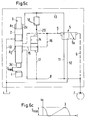
- 5a to c relate to the limit case that the pilot valve 14 has already reached the opening position shown in FIG. 5a before a connection between the lines 15 and 8 has been established via the front cylinder space section 2b; the position of the percussion piston 3 corresponding to the representation according to FIG. 5a is indicated in FIG. 6a. This can occur if the striking mechanism is switched on and the later operating pressure has not yet been set during the first working cycle or if the time delay ⁇ t2 via the delay element 18 is too short.
- the control valve 5 Due to the premature switchover of the pilot valve 14, the control valve 5 is brought into the working stroke position exclusively as a function of the position of the percussion piston, as soon as - as indicated in FIGS. 5b and 6b - the percussion piston 3 has traveled the path S1.
- the input line 15 to the pressure line 8 via the front cylinder space section 2b is connected and accordingly the adjustment of the control slide 5a into the working stroke position is initiated via the larger slide area A S2 then pressurized.
- the percussion piston 3 strikes extremely hard material via its tool 4 and the delay time .DELTA.t2 on the delay element 18 is very long, it may reach the structurally predetermined top dead center or reversal point, through which the maximum percussion piston, before the pilot valve 14 is switched into the open position -Path S max is set.
- the return stroke movement of the percussion piston 3 "overtakes" the changeover of the pilot valve 14 in that the control line 9 is connected to the pressure line 8 via the front cylinder space section 2b and the control slide 5a (with the time delay ⁇ t3) begins to switch to the working stroke position .
- a suitable arrangement of the mouth 9a of the control line 9 with respect to the working cylinder 2 prevents the percussion piston 3 from striking the associated housing and the striking mechanism from being overstressed.
- the pilot valve 14 and the control valve 5 are additionally assigned a shuttle valve 21, the structure and mode of operation of which are known from the document DE-C2-34 43 542.
- the shuttle valve is connected to the pilot valve 14 via the additional line 16, to the control line 9 via a line 16a connected to the additional line 16 and to the larger slide area of the control valve 5 via a further line 16b.
- the shuttle valve Under the action of its two adjustment surfaces W 1 and W 2 , the shuttle valve can assume the blocking position shown or an open position; in the latter line 16b is connected to return line 10 via lines 16a, 22 and 12.
- the shuttle valve has a throttle 21a, which is installed between the mouths of lines 9 and 16b in line 16a. Under the action of the throttle 21a, a pressure builds up on the control surfaces W 1 and W 2 , which results in the required switching of the shuttle valve 21 into the blocking or the open position.
- the shuttle valve 21 ensures that the switchover of the control slide 5a from the working stroke position to the return stroke position - regardless of the position of the percussion piston 3 - is not hindered. This is done in that the line 16b is depressurized via the lines 16a, 22, 12 and 10 with the shuttle valve 21 taking the open position. If the pilot valve 14 has reached the open position, the control valve 5 is pressurized via the lines 16, 16a and 16b and thus initiates its switchover to the stroke stroke position; the shuttle valve 21 ensures that the connection between the lines 16, 16a, 9, and 16b on the one hand and the lines 22, 12 and 10 on the other hand is interrupted.
- the mouth 9a of the control line 9 is - adapted to the design of the percussion piston 3 - so that a connection is made between the lines 9 and 10 before the impact of the percussion piston 3 on the associated tool 4 via the circumferential groove 3c.
- the consequence of this is that the switchover of the control valve 5 (shown in FIG. 9) can be initiated in the return stroke position.
- the control valve 5 may be switched depending on the path. This is done in that the piston collar 3b releases the opening 9a in the course of the return stroke movement, so that the working pressure is applied to it via the front cylinder space section 2b and the pressure line 8.
- the control line 9 thus under pressure initiates the switchover of the control valve 5 (cf. FIG. 9) to the working stroke position with the time delay ⁇ t3.
- FIG. 11 differs from the embodiment according to FIG. 9 in that the lines 8, 15 and 9 are arranged with their openings 8a, 15a and 9a, as shown for example in FIG. 3a.
- the input line 15 is only released depending on the path, so it is not constantly under working pressure. Rather, it is about the front Cylinder chamber section 2b is only connected to the pressure line 8 after the percussion piston 3 has covered a minimum stroke (corresponding to the axial distance between the orifices 8a and 15a).
- the mouth 9a of the control line 9 represents a long stroke bore; this makes it possible to apply control pressure to the control line 9, regardless of the position of the pilot valve 14, and thereby initiate the switchover of the control valve 5 (shown in FIG. 9) into the working stroke position. This is done in that the piston collar 3b moves past the opening 9a, so that this is also connected to the pressure line 8 via the front cylinder section 2b.
- FIG. 12a shows an embodiment of the striking mechanism 1 which corresponds to the embodiment, for example according to FIG. 3a, with the proviso that the valves 5 and 14 (corresponding to FIG. 9) are assigned a shuttle valve 21.
- a check valve 19 is connected in parallel with the delay element 18.
- the check valve 19 ensures the rapid return stroke of the pilot valve 14.
- the delay element 18 can also work towards the tank and is accordingly independent of the return pressure which may arise in the striking mechanism.
- the return stroke of the pilot valve 14 is influenced via the check valve 19.
- the aforementioned delay element 18 is designed as a current regulator 23, by which - independent from the inlet pressure - a constant volume flow always flows through. Accordingly, the second time delay .DELTA.t2 can be kept constant for a predetermined setting of the current regulator regardless of the working pressure (system pressure).
- the adjustability of the size of the current regulator setpoint is indicated by an arrow 23a.
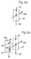
- the flow controller 23 is designed to be adjustable in a pressure-dependent manner, ie the setpoint value of the volume flow can be changed as a function of the working pressure p 0 by adjusting the passage cross section in the flow controller (FIG. 13b).
- the cross-sectional adjustment (indicated by the arrow 23a) is equipped with an actuator which has an adjusting piston 24 with a piston rod 24a and a return spring 25; the displacement of the piston rod 24a relative to the current regulator 23 results in a change in the size of the passage cross section.
- the actuator and the flow controller are designed in such a way that with decreasing working pressure p 0 (corresponding to a displacement of the piston rod 24a upwards) the flow controller 23 is influenced in such a way that the set value of the volume flow assumes a larger value.
- This adjustment in the direction of a larger setpoint of the volume flow is synonymous with a shortening of the second time delay ⁇ t2.
- the current regulator 23 in cooperation with the associated actuator thus ensures that the second time delay ⁇ t2 - and thus the remaining return stroke of the percussion piston - is adapted depending on the material as a function of the working pressure or system pressure: With a decreasing reflectance R and accordingly a decreasing working pressure or System pressure, the remaining return stroke becomes shorter, correspondingly longer with increasing reflectivity.
- the operation of the current regulator 23 can be advantageously changed in that the restoring force of the restoring spring 25 is connected in parallel with an adjustable, constant additional force, which also counteracts a displacement of the adjusting piston 24 in the direction of the restoring spring 25.
- This additional force can be generated in a simple manner in that the return spring 25 receives a pretension, under the effect of which it is held against a stop surface, not shown.
- An increase in the preload has the result that the setpoint value of the volume flow specified via the current regulator 23 becomes greater at the same working pressure or system pressure p 0 .
- ⁇ t2 becomes smaller and the size of the residual return stroke decreases with the same working pressure or system pressure and the same degree of reflection. Accordingly, the point R 0 on the characteristic curve shifts to the right.
- the magnitude of the pretensioning force can therefore be used to specify or change the limit value R 0 of the reflectance R, from which the setpoint of the current regulator 23 and thus the magnitude of the second time delay ⁇ t2 - as shown in FIGS. 2c and 2d - for the remaining Return stroke is the determining size.
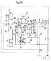
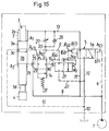
- FIGS. 14 and 15 should also take into account the idea that the working pressure or system pressure increases with increasing reflectance R and accordingly the second time delay ⁇ t2 should be greater.
- pilot line 20 (with the elimination of the delay element 18) merges into the changeover line 13 with the interposition of an adjusting diaphragm 27 and a check valve 28 connected in parallel therewith.
- a control line 29 also extends from the pressure line 8, via which a surface A V3 of the pilot valve 14 is pressurized.
- the two embodiments in question differ in that in the embodiment according to FIG. 14 the return line 17 connected to the pressure line 8 is equipped with a pressure reducing valve 30, while the embodiment according to FIG. 15 has a return spring 31 acting on the pilot valve 14.
- the pressure reducing valve 30 reduces the working pressure or system pressure in the return line 17 to a fixed predetermined value, which acts on the area A V1 and thus causes a constant force in the opening direction of the pilot valve 14. This force in the opening direction is counteracted by the compressive forces acting on surfaces A V2 and A V3 .
- the control pressure in the pilot line 20 is adjusted so that a force equilibrium is present on the pilot valve 14. Accordingly, the control pressure in the pilot line 20 decreases with increasing working pressure and vice versa.
- the restoring force acting in the opening direction of the pilot valve 14 is generated by the restoring spring 31 already mentioned. Otherwise, the same principles apply as in the embodiment according to FIG. 14: With increasing size of the reflectance R, the working pressure increases. Due to the force equilibrium prevailing on the pilot valve 14, the volume flow passing through the adjusting orifice 27 decreases, since the control pressure in the pilot line 20 drops with increasing working pressure. Accordingly, the adjustment speed of the pilot valve 14 decreases, with the result that the second time delay ⁇ t2 (as desired) takes on a larger value.
- the advantage achieved with the invention is in particular that the use of simple and less prone to failure additional elements creates the possibility of automatically adjusting the impact force generated by a striking mechanism to the hardness of the material to be processed. This also has the consequence that the economy of the striking mechanism is improved and its stress is reduced.
Landscapes
- Engineering & Computer Science (AREA)
- Physics & Mathematics (AREA)
- Fluid Mechanics (AREA)
- Mechanical Engineering (AREA)
- Automation & Control Theory (AREA)
- Percussive Tools And Related Accessories (AREA)
Applications Claiming Priority (2)
| Application Number | Priority Date | Filing Date | Title |
|---|---|---|---|
| DE19545708 | 1995-12-07 | ||
| DE1995145708 DE19545708A1 (de) | 1995-12-07 | 1995-12-07 | Verfahren zur Beeinflussung des Betriebsverhaltens eines fluidbetriebenen Schlagwerks und zur Durchführung des Verfahrens geeignetes Schlagwerk |
Publications (2)
| Publication Number | Publication Date |
|---|---|
| EP0778110A2 true EP0778110A2 (fr) | 1997-06-11 |
| EP0778110A3 EP0778110A3 (fr) | 1998-06-10 |
Family
ID=7779480
Family Applications (1)
| Application Number | Title | Priority Date | Filing Date |
|---|---|---|---|
| EP96119281A Withdrawn EP0778110A3 (fr) | 1995-12-07 | 1996-12-02 | Procédé pour la modification du mode de fonctionnement d'un mécanisme de percussion actionné par un fluide et mécanisme de percussion pour la mise en oeuvre du procédé |
Country Status (3)
| Country | Link |
|---|---|
| EP (1) | EP0778110A3 (fr) |
| JP (1) | JPH09174461A (fr) |
| DE (1) | DE19545708A1 (fr) |
Cited By (4)
| Publication number | Priority date | Publication date | Assignee | Title |
|---|---|---|---|---|
| WO2002090015A1 (fr) * | 2001-05-10 | 2002-11-14 | Morphic Technologies Aktiebolag (Publ) | Procede utilisant une energie cinetique elevee pour le travail de materiaux |
| EP1861228A4 (fr) * | 2005-03-24 | 2013-04-24 | Sandvik Mining & Constr Oy | Dispositif a percussion |
| WO2013083903A1 (fr) * | 2011-12-09 | 2013-06-13 | Montabert | Procédé de commutation de la course de frappe d'un piston de frappe d'un appareil à percussions |
| US9840000B2 (en) | 2014-12-17 | 2017-12-12 | Caterpillar Inc. | Hydraulic hammer having variable stroke control |
Families Citing this family (4)
| Publication number | Priority date | Publication date | Assignee | Title |
|---|---|---|---|---|
| DE19923680B4 (de) * | 1999-05-22 | 2004-02-26 | Atlas Copco Construction Tools Gmbh | Verfahren zur Ermittlung der Betriebsdauer und des Einsatz-Zustands eines hydraulischen Schlagaggregats, insbesondere Hydraulikhammer, sowie Vorrichtung zur Durchführung des Verfahrens |
| JP4463381B2 (ja) * | 2000-06-01 | 2010-05-19 | 古河機械金属株式会社 | 油圧さく岩機のダンパ圧力制御装置 |
| KR100569198B1 (ko) * | 2003-05-06 | 2006-04-07 | 이일재 | 유압타격장치 |
| JP4488694B2 (ja) * | 2003-06-25 | 2010-06-23 | 甲南電機株式会社 | 液圧式打撃装置 |
Citations (1)
| Publication number | Priority date | Publication date | Assignee | Title |
|---|---|---|---|---|
| DE3443542C2 (fr) | 1984-11-29 | 1990-07-26 | Fried. Krupp Gmbh, 4300 Essen, De |
Family Cites Families (7)
| Publication number | Priority date | Publication date | Assignee | Title |
|---|---|---|---|---|
| US3955478A (en) * | 1973-10-29 | 1976-05-11 | Dresser Industries, Inc. | Hydraulically powered percussion drill |
| DE3115361A1 (de) * | 1981-04-16 | 1982-10-28 | Hydroc Gesteinsbohrtechnik GmbH, 5960 Olpe | "hydraulische schlagvorrichtung" |
| SE8106907L (sv) * | 1981-11-20 | 1983-05-21 | Atlas Copco Ab | Sett att styra ett slagverk och slagverk |
| DE4019019A1 (de) * | 1990-06-14 | 1991-12-19 | Krupp Maschinentechnik | Verfahren zur ermittlung charakteristischer kenngroessen eines schlagwerks und einrichtung zur durchfuehrung des verfahrens |
| DE4019016A1 (de) * | 1990-06-14 | 1991-06-13 | Krupp Maschinentechnik | Verfahren zur beeinflussung des betriebsverhaltens eines schlagwerks und einrichtung zur durchfuehrung des verfahrens |
| DE4036918A1 (de) * | 1990-11-20 | 1992-05-21 | Krupp Maschinentechnik | Verfahren zur anpassung des arbeitsverhaltens eines schlagwerks an die haerte des zerkleinerungsmaterials und einrichtung zur durchfuehrung des verfahrens |
| DE19507348A1 (de) * | 1995-03-02 | 1996-09-05 | Krupp Maschinentechnik | Verfahren zur Beeinflussung des Betriebsverhaltens eines fluidbetriebenen Schlagwerks und zur Durchführung des Verfahrens geeignetes Schlagwerk |
-
1995
- 1995-12-07 DE DE1995145708 patent/DE19545708A1/de not_active Ceased
-
1996
- 1996-12-02 EP EP96119281A patent/EP0778110A3/fr not_active Withdrawn
- 1996-12-06 JP JP8327089A patent/JPH09174461A/ja active Pending
Patent Citations (1)
| Publication number | Priority date | Publication date | Assignee | Title |
|---|---|---|---|---|
| DE3443542C2 (fr) | 1984-11-29 | 1990-07-26 | Fried. Krupp Gmbh, 4300 Essen, De |
Cited By (8)
| Publication number | Priority date | Publication date | Assignee | Title |
|---|---|---|---|---|
| WO2002090015A1 (fr) * | 2001-05-10 | 2002-11-14 | Morphic Technologies Aktiebolag (Publ) | Procede utilisant une energie cinetique elevee pour le travail de materiaux |
| US7104190B2 (en) | 2001-05-10 | 2006-09-12 | Morphic Technologies Aktiebolag (Publ) | Method employing high kinetic energy for working of material |
| AU2002308843B2 (en) * | 2001-05-10 | 2006-11-09 | Cell Impact Ab | Method employing high kinetic energy for working of material |
| EP1861228A4 (fr) * | 2005-03-24 | 2013-04-24 | Sandvik Mining & Constr Oy | Dispositif a percussion |
| WO2013083903A1 (fr) * | 2011-12-09 | 2013-06-13 | Montabert | Procédé de commutation de la course de frappe d'un piston de frappe d'un appareil à percussions |
| FR2983760A1 (fr) * | 2011-12-09 | 2013-06-14 | Montabert Roger | Procede de commutation de la course de frappe d'un piston de frappe d'un appareil a percussions |
| US9981371B2 (en) | 2011-12-09 | 2018-05-29 | Montabert | Method for switching the striking stroke of a striking piston of a percussion device |
| US9840000B2 (en) | 2014-12-17 | 2017-12-12 | Caterpillar Inc. | Hydraulic hammer having variable stroke control |
Also Published As
| Publication number | Publication date |
|---|---|
| JPH09174461A (ja) | 1997-07-08 |
| DE19545708A1 (de) | 1997-06-12 |
| EP0778110A3 (fr) | 1998-06-10 |
Similar Documents
| Publication | Publication Date | Title |
|---|---|---|
| EP0827813B1 (fr) | Dispositif hydraulique à percussion avec inversion automatique de la course du piston | |
| DE2512731C2 (fr) | ||
| DE69424286T2 (de) | Bidirektionale hydraulische schere | |
| EP1256419B1 (fr) | Méthode et pour la protection d'un outil de percussion hydraulique contre les effects des frappes à vide | |
| DE19525431C2 (de) | Presse zum Stanzen von Löchern in ein Werkstück | |
| DE3347605C2 (de) | Pneumatisches Werkzeug | |
| DE102004035306A1 (de) | Druckmittelbetriebene Schlagvorrichtung insbesondere Hydraulikhammer | |
| DE69227925T2 (de) | Hydraulische pfahlramme | |
| EP1136189B1 (fr) | Marteau à coup actionné hydrauliquement | |
| DE4027021A1 (de) | Hydraulisch betriebene schlagdrehbohrvorrichtung, insbesondere zum ankerlochbohren | |
| EP0475171A2 (fr) | Mécanisme à coup actionné hydrauliquement | |
| EP0486871B1 (fr) | Méthode pour assister le concassage par des dispositifs de démolition et dispositif appliqué dans cette méthode | |
| EP0778110A2 (fr) | Procédé pour la modification du mode de fonctionnement d'un mécanisme de percussion actionné par un fluide et mécanisme de percussion pour la mise en oeuvre du procédé | |
| DE2461633C2 (de) | Hydraulische Schlagvorrichtung | |
| WO1997035114A1 (fr) | Machine-outil hydropneumatique | |
| EP0847836B1 (fr) | Appareil à percussion mû par un fluide sous pression | |
| DE112004002298T5 (de) | Hydraulische Schlagvorrichtung | |
| DE2107510A1 (de) | Hydraulisches Schlagwerkzeug | |
| DE19507348A1 (de) | Verfahren zur Beeinflussung des Betriebsverhaltens eines fluidbetriebenen Schlagwerks und zur Durchführung des Verfahrens geeignetes Schlagwerk | |
| WO1995022442A1 (fr) | Marteau-piqueur hydraulique | |
| DE2349296A1 (de) | Druckluft-schlagmaschine | |
| EP0933169B1 (fr) | Dispositif de percussion actionné par un fluide | |
| EP0655205A2 (fr) | Presse à fluide sous-pression en particulier presse hydraulique à oeillets pour perforer des bandes et fixer des oeillets renforcés autour du trou | |
| DE68928143T2 (de) | Verfahren zum automatischen Anpassen der Funktionsparameter eines Schlagapparates | |
| DE2914933C2 (de) | Druckmittelbetriebene Fernsteuerung für die pneumatische Hauptsteuereinheit eines Gesenkschmiedehammers, insbesondere eines Gegenschlaghammers |
Legal Events
| Date | Code | Title | Description |
|---|---|---|---|
| PUAI | Public reference made under article 153(3) epc to a published international application that has entered the european phase |
Free format text: ORIGINAL CODE: 0009012 |
|
| AK | Designated contracting states |
Kind code of ref document: A2 Designated state(s): DE FR IT |
|
| PUAL | Search report despatched |
Free format text: ORIGINAL CODE: 0009013 |
|
| AK | Designated contracting states |
Kind code of ref document: A3 Designated state(s): DE FR IT |
|
| STAA | Information on the status of an ep patent application or granted ep patent |
Free format text: STATUS: THE APPLICATION HAS BEEN WITHDRAWN |
|
| 18W | Application withdrawn |
Withdrawal date: 19980914 |