EP0778366B1 - Verfahren und vorrichtung zum selektiven steuern von schaltgabeln an einer torchon-klöppelmaschine - Google Patents
Verfahren und vorrichtung zum selektiven steuern von schaltgabeln an einer torchon-klöppelmaschine Download PDFInfo
- Publication number
- EP0778366B1 EP0778366B1 EP96917697A EP96917697A EP0778366B1 EP 0778366 B1 EP0778366 B1 EP 0778366B1 EP 96917697 A EP96917697 A EP 96917697A EP 96917697 A EP96917697 A EP 96917697A EP 0778366 B1 EP0778366 B1 EP 0778366B1
- Authority
- EP
- European Patent Office
- Prior art keywords
- fork
- solenoids
- pawl
- solenoid
- selector rods
- Prior art date
- Legal status (The legal status is an assumption and is not a legal conclusion. Google has not performed a legal analysis and makes no representation as to the accuracy of the status listed.)
- Expired - Lifetime
Links
- 238000000034 method Methods 0.000 title claims description 18
- 238000006073 displacement reaction Methods 0.000 claims description 5
- 230000003993 interaction Effects 0.000 claims description 2
- 230000033001 locomotion Effects 0.000 description 7
- 230000005540 biological transmission Effects 0.000 description 6
- 230000006835 compression Effects 0.000 description 6
- 238000007906 compression Methods 0.000 description 6
- 238000009954 braiding Methods 0.000 description 3
- 238000010276 construction Methods 0.000 description 2
- 230000003028 elevating effect Effects 0.000 description 2
- 230000002093 peripheral effect Effects 0.000 description 2
- 230000004043 responsiveness Effects 0.000 description 2
- XEEYBQQBJWHFJM-UHFFFAOYSA-N Iron Chemical group [Fe] XEEYBQQBJWHFJM-UHFFFAOYSA-N 0.000 description 1
- 238000010586 diagram Methods 0.000 description 1
- 230000012447 hatching Effects 0.000 description 1
- 238000004519 manufacturing process Methods 0.000 description 1
- 230000001846 repelling effect Effects 0.000 description 1
Images


Classifications
-
- D—TEXTILES; PAPER
- D04—BRAIDING; LACE-MAKING; KNITTING; TRIMMINGS; NON-WOVEN FABRICS
- D04C—BRAIDING OR MANUFACTURE OF LACE, INCLUDING BOBBIN-NET OR CARBONISED LACE; BRAIDING MACHINES; BRAID; LACE
- D04C3/00—Braiding or lacing machines
- D04C3/02—Braiding or lacing machines with spool carriers guided by track plates or by bobbin heads exclusively
- D04C3/24—Devices for controlling spool carriers to obtain patterns, e.g. devices on guides or track plates
-
- D—TEXTILES; PAPER
- D04—BRAIDING; LACE-MAKING; KNITTING; TRIMMINGS; NON-WOVEN FABRICS
- D04C—BRAIDING OR MANUFACTURE OF LACE, INCLUDING BOBBIN-NET OR CARBONISED LACE; BRAIDING MACHINES; BRAID; LACE
- D04C3/00—Braiding or lacing machines
- D04C3/02—Braiding or lacing machines with spool carriers guided by track plates or by bobbin heads exclusively
- D04C3/32—Pattern input
Definitions
- the present invention relates to operation selecting control method and apparatus for shifter fork of torchon lace machine and, more particularly, to such method and apparatus using a separate electronic control portion producing a signal according to which the mode of operation of the shifter fork is selected or switched.
- a torchon lace machine in which the mode of operation of the shifter fork is selected according to a signal from an electronic control portion as described above has been well known.
- the shifter fork is fitted over a fork shaft.
- Vertical movement of this shifter fork is induced by a driving means.
- this driving means uses a spindle plate for rotating a spindle over which a bobbin is fitted.
- a threaded, driven wheel is fitted over the rotating shaft of the spindle plate.
- a cam is fitted over the driven wheel.
- a driving lever produces a driving force by making use of displacement of this cam.
- JP-B-60028702 (UTILITY MODEL)
- JP-B-61038941 (UTILITY MODEL)
- a selector rod is rotatably mounted to a lower portion of a fork shaft.
- the selector rod is connected to the plunger of a solenoid which, in turn, is secured to the housing of the machine.
- the JP-B-61038941(UTILITY MODEL) discloses a structure where a plurality of levers utilizing displacement of the aforementioned cam rotate a shaft in which a selector rod is slidably fitted. A control rod protruding from this shaft is rotated at the same time and brought close to a magnet coil. Then, the control rod is either attracted or unattracted. Thus, the mode of operation can be selected.
- a selector rod utilizing rotation of the shaft of a rotary solenoid is mounted between a fork shaft and the end of a driver lever to which a driving force is transmitted, the end being located in a diametrically opposite relation to the side of the driver lever on which the cam acts.
- the present invention has been made. It is an object of the invention to provide operation selecting control method and apparatus for shifter fork of torchon lace machine which is free of the foregoing problems and capable of sufficiently following up high-speed rotation without erroneous function and which is preferably simple in constitution.
- a selector rod is made to be movably held by a part of driving means.
- the selector rod is so mounted as to act on a part of a fork shaft or the shifter fork.
- the selector rod is equipped with a permanent magnet.
- a solenoid is mounted close to the selector rod so that the solenoid can magnetically act on the selector rod.
- the mode of operation of the selector rod can be quickly and precisely selected by energizing or deenergizing the solenoid.
- a repelling action occurs with the permanent magnet, thus moving the selector rod.
- the selector rod is kept at rest.
- the solenoid When the selector rod is not moved as described above, the solenoid is energized to produce an attracting magnetic field with the permanent magnet by dissimilar poles. In consequence, the selector rod can be maintained stationary. In this case, the selector rod can be maintained in its unoperated state more certainly.
- the selector rod When the solenoid is energized to move the selector rod into its operated or unoperated position as described above, the selector rod is preferably kept out of contact with a member on the side of the solenoid. This circumvents collision or strong abutment during the operation. Hence, an erroneous function is prevented. As a result, the machine can accommodate itself to high-speed rotation without difficulty.
- the above-mentioned returning means is a returning member acting on a lower portion of the selector rod
- engagement with the inclined surface of the returning member forces the selector rod to go back to the solenoid side.
- the two solenoids attract and repel coordinately.
- the coordinate action further enhances the responsiveness of the selector rod.
- An operation selecting control apparatus for shifter fork in accordance with the present invention comprises an elevatable member, a retaining member, a displacement-imparting member, a pawl, and an actuator.
- the elevatable member extends in the axial direction of a fork shaft to which the shifter fork is mounted, the shifter fork being moved back and forth.
- the retaining member is firmly mounted to the housing of the machine.
- the elevatable member is slidably held to the retaining member.
- the displacement-imparting member imparts a displacement to the elevatable member to drive it.
- the pawl is pivoted to a part of the elevatable member and mounted so as to be swingable. Thus, the pawl can come into and out of engagement with the shifter fork or fork shaft.
- the shifter fork or fork shaft has an engaging portion.
- the actuator brings the pawl into or out of engagement with the engaging portion of the shifter fork or fork shaft by swinging the pawl.
- the actuator acts to bring the pawl into engagement with the engaging portion of the shifter fork or fork shaft or to keep the pawl out of engagement. In this way, upward and downward movement of the shifter fork can be readily selected.
- the actuator preferably makes use of interaction between a permanent magnet and the solenoid capable of appropriately acting on the permanent magnet which is mounted to the pawl.
- Fig. 1 is a fragmentary front elevation partially in cross section of a first embodiment of operation selecting control apparatus for a shifter fork according to the present invention and its associated parts.
- Fig. 2 is a fragmentary enlarged view of Fig. 1.
- Fig. 3 is a side elevation showing only an elevatable member of the apparatus.
- FIG. 1 A first embodiment of an operation selecting control apparatus for a shifter fork according to the invention is described by referring to Figs. 1-3.
- the spindle-driving member 3 is composed of a spindle plate 4, a clutch 5, and a drive gear 6.
- This drive gear 6 is rotatably and loosely mounted on a shaft 8, which is firmly secured to the machine housing 1 by nuts 7a, 7b, and 7c.
- the clutch 5 is slidably and rotatably inserted in a tubular shaft 9 that is formed integrally with the drive gear 6.
- the clutch 5 can come into and out of engagement with a clutch-engaging member 10 that is formed integrally with a lower part of the spindle plate 4.
- Indicated by 11 is a shifter fork to which upper fork 12 and lower fork 13 having bifurcate shape are firmly mounted.
- the clutch 5 is provided with a peripheral groove 5a and rotatably held by the lower fork 13.
- the shifter fork 11 is fitted over a fork shaft 14.
- the fork shaft 14 passed through the machine housing 1 with a bush 15 between them.
- Both ends of a compression spring 16 are positioned by washers 17a and 17b between the upper housing 2 and the shifter fork 11. The spring 16 is loosely inserted over the fork shaft 14 so as to bias the shifter fork 11 downward.
- An operation selecting control apparatus 18 for shift fork is constructed in the manner described below.
- This selecting control apparatus comprises a retaining member 19 affixed to the machine housing 1 by a screw means or the like, an elevatable member 20 held inside the retaining member 19 so as to be slidable vertically, solenoids 21a and 21b attached to the inner side surface of the retaining member 19 to form an actuator, swingable pawls 23a and 23b forming selector rods, and permanent magnets 22a and 22b mounted on the pawls 23a and 23b, respectively.
- These pawls 23a and 23b are held by pivots 28a and 28b in a face-to-face relation to the solenoids 21a and 21b, respectively.
- These permanent magnets 22a and 22b are fitted on an opposite relation to the solenoids 21a and 21b, respectively, so that these solenoids can magnetically act on the magnets, respectively.
- These permanent magnets 22a and 22b are so arranged that during energization of the solenoids 21a and 21b to move the pawls, the magnets are magnetized with the same magnetic poles as their respective geometrically opposite magnetic poles of the solenoids.
- each of the solenoids 21a and 21b has an iron core.
- the operation selecting control apparatus further includes a substantially L-shaped displacement-imparting member 24 kept in abutment with the bottom surface 20b1 of the elevatable member 20 and a support member 25 mounted to the machine housing 1.
- the displacement-imparting member 24 is rotatably held by the support member 25 via a bearing (not shown) and a support pin 27a.
- the solenoids 21a and 21b are connected with a control portion (not shown) by electric wires to permit energization of the solenoids. It is also possible to eliminate the wires by supplying an induced electromotive force to the solenoids and supplying a control signal to a receiving portion by radio.
- the elevatable member 20 has an upper portion 20a and a lower portion 20b indicated by hatching. These upper and lower portions are centrally provided with holes to permit sliding movement of the fork shaft 14. A hole 30 in the lower portion 20b of the elevatable member is so formed that it is not affected by the fork shaft 14 regardless of the way the elevatable member 20 moves upward or downward.
- a rod end 26 is rotatably attached to the lower end of the displacement-imparting member 24 via a bearing (not shown) and a pivotal pin 27b.
- a shifter fork-driving displacement-transmitting member 29 which is screwed over the rod end 26 is pulled in the direction indicated by the arrow A, the displacement-imparting member 24 rotates to push up the elevatable member 20 in the direction indicated by the arrow B.
- the shifter fork-driving displacement-transmitting member 29 is so constructed that it is reciprocated in the direction indicated by the arrow A in Fig. 1, for example, in synchronism with rotation of the main shaft of the torchon lace machine.
- the solenoids 21a and 21b when the solenoids 21a and 21b are not energized, the permanent magnets 22a and 22b pass through a slot 32 formed in the side surface of the elevatable member 20 and are attracted and about to be stuck to the cores of the solenoids 21a and 21b.
- protrusions 20a1 and 20a2 on the upper portion of the elevatable member 20a hinder the sticking and maintain the permanent magnets close to the solenoids 21a and 21b, as shown in Figs. 1 and 2.
- the pawls 23a and 23b move upward without acting on the fork shaft 14 and so the fork shaft 14 remains stationary.
- the solenoids 21a and 21b When energized, the solenoids 21a and 21b are magnetized with the same poles as their respective geometrically opposite south and north poles of the permanent magnets 22a and 22b.
- the resulting magnetic field repulses the pawls 23a and 23b in the directions indicated by the arrows C1 and C2 in Figs. 1 and 2 because of similar magnetic poles.
- engaging portions 23a1 and 23b1 of the pawls 23a and 23b, respectively can be engaged in notches 14a and 14b formed in the fork shaft.
- the elevatable member 20 is raised by the displacement-imparting member 24.
- the engaging portions 23a1 and 23b1 are engaged in the notches 14a and 14b, respectively.
- the fork shaft 14 is raised.
- the combination of the permanent magnets and solenoids brings the pawls into or out of engagement with the engaging portions of the shifter fork or fork shaft.
- the amount of displacement may be controlled or selected directly or via a lever or the like, using piezoelectric devices.
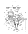
- FIG. 4 A second embodiment of the operation selecting control method and apparatus for shifter fork according to the invention is next described by referring to Fig. 4. It is to be noted that like components are indicated by like reference numerals in both embodiments, such as the spindle-driving member 3.
- the shifter fork 11 and a collar 54 to be engaged are fitted over a fork shaft 141.
- the collar 54 forms an engaging portion bearing against the bottom of the shifter fork 11.
- the fork shaft is slidably fitted in an upper portion 202a of the elevatable member, which is slidably held within a retaining member 191 screwed to the machine housing 1.
- Both ends of the compression spring 16 are positioned by washers 17a and 17b between the upper machine housing 2 and the shifter fork 11. The spring 16 is loosely inserted over the fork shaft 141 so as to bias it downward.
- Indicated by 181 is an operation selecting control apparatus for shifter fork of the second embodiment and constructed as follows.
- This apparatus comprises the retaining member 191 affixedly mounted to the machine housing 1 by a screw means or the like, an elevatable member 202 held so as to be slidable vertically inside the retaining member 191, a pawl 231 acting as a selector rod, and a permanent magnet 221 mounted on the pawl 231 which can be swung.
- the pawl 231 is rotatably held by a pivot 281 in a notch formed in the upper portion 202a of the elevatable member.
- the apparatus further includes a compression spring 161 located under the retaining member 191, a roller 272 bearing against the bottom surface 202c of the elevatable member, a displacement-imparting member 241 rotatably held by a pivotal pin 271a, a transmission roller 47 connected with the displacement- imparting member 241, a cam 46 fitted over the tubular shaft 9, a nonmagnetic L-shaped member 53 screwed to the machine housing 1, and a solenoid 212 acting as an actuator.
- the lower portion 202b of the elevatable member is inserted in the compression spring 161.
- the roller 272 is rotatably mounted to the displacement-imparting member 241 via a pivotal pin 271b.
- the profile of the cam 46 bears against the transmission roller.
- the solenoid 212 is rigidly mounted to the L-shaped member 53 and is disposed in face-to-face (geometrically opposite) position to the permanent magnet 221 so as to magnetically act on the permanent magnet 221.
- the solenoid 212 is so set up that when it is energized to move the pawl, the solenoid is magnetized with the same magnetic poles as the north and south poles of the permanent magnet 221.
- a hole 300 is formed in the center of the upper portion 202a of the elevatable member in such a way that the elevatable member 202 is not affected by the fork shaft 141 regardless of the way in which the elevatable member 200 is moving upward or downward.
- the cam 46 is designed to follow the tubular shaft 9 when it is rotating.
- the roller 47 is pushed in the direction indicated by the arrow A2, and the displacement-imparting member 241 shifts the elevatable member 202 in the direction indicated by the arrow B2.
- the solenoid 212 when the solenoid 212 is not energized, if the elevating member 202 is moving downward, the right side 231a1 of a downwardly protruding end of the pawl 231 comes into contact with the inner surface of a notch 191a formed in the retaining member 191 that is a returning means. The pawl 231 is urged to tilt toward the solenoid 212. At the same time, the permanent magnet 221 is attracted and about to be stuck to the core of the solenoid 212.
- the left side 231a2 of the downwardly protruding end of the pawl 231 bears against an inclined surface 202a1 defining a notch in the upper portion 202a of the elevatable member. This hinders further inclination of the pawl 231. Consequently, the pawl 231 is kept close to the L-shaped member 53. Under this condition, the pawl 231 does not act on the collar 54 to be engaged that is an engaging portion fitted over the fork shaft 141. Since the pawl 231 moves upward without acting on the fork shaft 141, the shaft 141 remains at rest.
- the solenoid 212 When energized, the solenoid 212 is energized with the same magnetic poles as the south and north poles of the permanent magnet 221, thus producing a repulsive magnetic field. This repels the pawl 231 in the direction indicated by the arrow C4, thus permitting the pawl 231 to act on the collar 54 to be engaged fitted over the fork shaft 141. As the elevatable member 202 is raised by the displacement-imparting member 241, the pawl 231 comes into engagement with the collar 54, thus elevating the fork shaft 141.
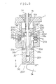
- Figs. 5 and 6 illustrate a third embodiment of operation selecting control method and apparatus for shifter fork in accordance with the present invention. Again, those components and structures which are common to their counterparts of the first embodiment, such as spindle-driving member 3, are indicated by the same reference numerals as used in the first embodiment.
- a shifter fork 11 is fitted over a fork shaft 143, which is slidably fitted in the top portion 193a of a retaining member 193 rigidly fixed to the machine housing 1 by a screw means or the like. Both ends of a compression spring 16 are positioned by washers 17a and 17b between an upper housing 2 and the shifter fork 11. The spring 16 is loosely inserted over the fork shaft 143 so as to bias the shifter fork 11 downward.
- 183 is an operation selecting control apparatus for shifter fork of the third embodiment. This apparatus is constructed in the manner described below.
- An elevatable member 204 is vertically slidably held inside the retaining member 193 that is securely mounted to the machine housing 1.
- a cam member 54 forming a returning means is inserted in recesses 57 and 60.
- the recess 57 reaches the depth of the inner bottom 204a of the elevatable member 204.
- the recess 60 is formed at the bottom of the retaining member 193.
- the cam member 54 is firmly held against the retaining member 193 by a snap ring 58.
- a pawl 233 acting as a selector rod is rotatably mounted in the recess 57 in the elevatable member 204 by a pivot 283.
- the pawl 233 is mounted so as to be swingable.
- a permanent magnet 223 is mounted on the pawl 233.
- a compression spring 164 is disposed between a washer 61 and a step portion of the retaining member 193, the washer being mounted at the lower end of the elevatable member 204 which is inserted in the spring 164. This spring biases the elevatable member 204 downward.
- a roller 274 abutting against the bottom surface 204b of the elevatable member is rotatably mounted to the displacement-imparting member 242 via a pivotal pin 273b.
- the displacement-imparting member 242 is rotatably mounted via a pivotal pin 273a.
- a transmission roller 470 is connected to the displacement-imparting member 242.
- a solenoid member 56 firmly mounted to the retaining member 193 by a screw means or the like has a solenoid 214 which is located opposite to the permanent magnet 223 so as to be capable of acting magnetically on the magnet.
- This solenoid 214 is so set up that when it is energized to move the pawl, the solenoid is magnetized with the same magnetic poles as their respective geometrically opposite north and south poles of the permanent magnet 223.
- a stopper pin 53 is mounted in the recess 57 in the elevatable member 204 so that when the pawl 233 is repelled by the solenoid 214, the pin 53 maintains the pawl 233 in an appropriate position.
- stopper means such as a protrusion performing the same function may be mounted instead of the stopper pin.
- the cam member 54 is so mounted that it not affected by the inner bottom 204a of the elevatable member 204 regardless of the way in which the elevatable member 204 is moving upward or downward.
- the cam 46 follows the tubular shaft 9 when it is rotating.
- the roller is pushed in the direction indicated by the arrow A5.
- the displacement- imparting member 242 displaces the elevatable member 204 in the direction indicated by the arrow B4.
- the solenoid 214 When the solenoid 214 is energized, it is magnetized with the same magnetic poles as their respective geometrically opposite north and south poles of the permanent magnet 223, thus producing a repulsive magnetic field. This repulses the pawl 233 in the direction indicated by the arrow C6. Thus, the pawl 233 rotates until it bears against the stopper pin 53, and then the pawl can act on the fork shaft 143. As the elevatable member 204 is moved upward by the displacement-imparting member 242, the pawl raises the fork shaft 143.
- the shifter fork 11 shifts the clutch 5 into a position where the clutch can engage the clutch-engaging member 10. Under this condition, the drive gear 6 is rotated. The rotating force is transmitted to the spindle plate 4 via the clutch-engaging member 10.
- a bush can be fitted over the outer surface of the elevatable member 204 so as to cover the recess 57 in the elevatable member 204 or so as to close up the recess 57 partially.
- a stopper ring can be fitted in the recess 57 near its top side.
- a returning means is used to return the pawls (selector rods) to their home positions close to the solenoids.
- the returning means makes use of the magnetic forces of permanent magnets.
- a part of a retaining member against which the lower end of each pawl bears during downward movement of an elevatable member is used as a part of a returning member.
- the inclined surface of a cam member against which the lower end of each pawl bears is used as the inclined surface of a returning member.
- a second solenoid is mounted on the opposite side of a selector rod from the aforementioned solenoid used for operation of the selector rod, and returning action is obtained utilizing this second solenoid.
- an elevatable means (not shown) can be elevated and lowered by an appropriate displacement- imparting means in the directions indicated by the arrows B5.
- a pawl 235 acting as a selector rod is held to this elevatable means by a pivot 285 so as to be swingable in the directions indicated by the arrows C5.
- a permanent magnet 225 is attached to this pawl 235.
- Two solenoids 215a and 215b are mounted on opposite sides of the pawl 235. When the solenoids are energized to move the pawls, the solenoids are magnetized with the similar magnetic poles as their respective geometrically opposite north and south poles of the permanent magnet 225.
- the attraction by the magnetic force of the permanent magnet 225 tilts the pawl toward the solenoid 215a and maintains the pawl close to this solenoid without energizing the solenoids 215a, 215b.
- the solenoid 215a is energized so that it is magnetized with the similar magnetic poles as their respective geometrically opposite north and south poles of the permanent magnet 225.
- a repulsive magnetic field is produced with the permanent magnet because of the dissimilar magnetic poles.
- the pawl 235 is moved into engagement with the fork shaft 145.
- the pawl is brought close to the solenoid 215b. This condition is maintained by the magnetic force of the permanent magnet 225.
- the solenoid 215b When the pawl 235 is returned to its unoperated position, the solenoid 215b is energized to produce a repulsive magnetic field with the permanent magnet 225 because of the similar magnetic poles. The pawl 235 is tilted toward the solenoid 215a.
- stoppers 65a and 65b restrict movement of the pawl 235 to a certain amount in order that the pawl 235 be kept close to the solenoid 215a or 215b.
- a plurality of torchon lace machines of the construction described above can be operated under control of a centralprocessing unit. Their states of braiding are all managed by this central-processing unit. That is, a group control system can be accomplished. In this way, manufacturing operations of the torchon lace machines can be managed more efficiently.
- a selector rod is made to act on the shifter fork or fork shaft by a repulsive magnetic field of a solenoid. Therefore, the selector rod can sufficiently follow rapid rotation without erroneous function. Especially advantageously, the selector rod neither collides nor presses against the solenoid. Furthermore, it is easy to cause the selector rod to act on the solenoid in a noncontacting manner. Consequently, less troubles such as breaking of coils take place, and excellent durability is obtained. Also, the reliability of the switching operation is improved.
- the apparatus is made up of a fewer number of components and simpler in structure than conventional. Therefore, the apparatus can be fabricated at lower cost. Furthermore, the apparatus can be adjusted quickly. In addition, the apparatus can be serviced readily and hence can be treated easily.
Landscapes
- Engineering & Computer Science (AREA)
- Textile Engineering (AREA)
- Braiding, Manufacturing Of Bobbin-Net Or Lace, And Manufacturing Of Nets By Knotting (AREA)
- Gear-Shifting Mechanisms (AREA)
- Forklifts And Lifting Vehicles (AREA)
Claims (7)
- Verfahren zur Betriebsart-Auswahlsteuerung für eine an einer Gabelachse (14) montierte Schaltgabel (11) einer Torchon-Klöppelmaschine, mit einem ein Auswahlsignal erzeugenden elektronischen Steuerteil und einer Antriebseinrichtung (20) zum Auswählen der Betriebsart der Schaltgabel gemäß dem Auswahlsignal, wobei die Antriebseinrichtung mit Wählstiften (23) versehen ist, wobeidie Wählstifte (23) an Teilen der Antriebseinrichtung (20) derart angebracht werden, daß sie bewegbar sind und auf Teile der Gabelachse (14) oder der Schaltgabel (11) einwirken können,an den Wählstiften (23) jeweils Permanentmagnete (22) angebracht werden,nahe den Wählstiften (23) Elektromagnete (21) derart montiert werden, daß sie jeweils auf die Wählstifte magnetisch einwirken können,die Elektromagnete (21) elektrisch erregt werden, um zwischen ihnen und den Dauermagneten (23) durch gleiche Magnetpole ein magnetisches Abstoßungsfeld zu erzeugen und dadurch die Wählstifte (23) in ihre Arbeitsstellungen, in denen sie auf die Gabelachse (14) oder die Schaltgabel (11) einwirken, oder in ihre Ruhestellungen zu bewegen, in denen sie dies nicht tun, unddie Elektromagnete (21) aberregt werden, wenn die Wählstifte (23) nicht bewegt werden,wodurch der Auswahlvorgang gesteuert wird.
- Verfahren nach Anspruch 1, wobei dann, wenn die Wählstifte (23) nicht bewegt werden, die Elektromagnete (21) erregt werden, um zwischen ihnen und den Dauermagneten (22) durch unterschiedliche Magnetpole ein Anziehungsmagnetfeld zu erzeugen und dadurch die Wählstifte stationär zu halten.
- Verfahren nach Anspruch 1 oder 2, wobei die Wählstifte dann, wenn sie durch Erregung der Elektromagnete (21) in ihre Arbeits- oder Ruhestellungen bewegt werden, außer Berührung mit seitlichen Teilen der Elektromagnete gehalten werden.
- Verfahren nach einem der Ansprüche 1 bis 3, wobei die Wählstifte (23), nachdem sie verschoben worden sind, durch eine Rückstelleinrichtung in ihre den Elektromagneten (21) nahen Ausgangsstellungen zurückgeführt werden.
- Verfahren nach Anspruch 4, wobei die Rückstelleinrichtung Rückstellglieder aufweist, die an unteren Teilen der Wählstifte (23) angreifen.
- Verfahren nach Anspruch 4, wobei die Rückstelleinrichtung zweite Elektromagnete aufweist, die jeweils an der dem betreffenden erstgenannten Elektromagnet (21) gegenüberliegenden Seite des entsprechenden Wählstiftes (23) angeordnet sind.
- Vorrichtung zur Betriebsart-Auswahlsteuerung für eine Schaltgabel (11) einer Torchon-Klöppelmaschine mit einem Gehäuse (1, 2) sowie fernereiner Gabelachse (14), an der die hin- und hergehende Schaltgabel (11) montiert ist,einem axial zu der Gabelachse (14) gelagerten anhebbaren Bauteil (20),einem an dem Gehäuse (1, 2) fest montierten Halteteil (19), das das anhebbare Bauteil (20) gleitend hält,einem Verschiebeteil (24), das dem anhebbaren Bauteil (20) zum Antrieb eine Verschiebung erteilt,einem an einem Teil der Schaltgabel (11) oder der Gabelachse (14) ausgebildeten Eingriffsteil (14a, 14b),einer Klinke (23), die an einem Teil des anhebbaren Elements (20) schwenkbar derart gelagert ist, daß sie in ihrer eingeschwenkten oder zurückgeschwenkten Stellung mit dem Eingriffsteil (14a, 14b) selektiv in Eingriff gelangt, undeinem Betätiger, der die Klinke (23) durch Wechselwirkung zwischen einem an ihr angebrachten Dauermagnet (22) und einem nahe dem Dauermagnet angebrachten Elektromagnet (21) wahlweise in bzw. außer Eingriff mit dem Eingriffsteil (14a, 14b) bringt.
Applications Claiming Priority (4)
| Application Number | Priority Date | Filing Date | Title |
|---|---|---|---|
| JP14725195 | 1995-06-14 | ||
| JP14725195 | 1995-06-14 | ||
| JP147251/95 | 1995-06-14 | ||
| PCT/JP1996/001647 WO1997000343A1 (fr) | 1995-06-14 | 1996-06-14 | Appareil et procede de commande de selection de fonctionnement pour fourchette de machine a dentelle torchon |
Publications (3)
| Publication Number | Publication Date |
|---|---|
| EP0778366A1 EP0778366A1 (de) | 1997-06-11 |
| EP0778366A4 EP0778366A4 (de) | 1997-11-19 |
| EP0778366B1 true EP0778366B1 (de) | 2001-04-04 |
Family
ID=15426010
Family Applications (1)
| Application Number | Title | Priority Date | Filing Date |
|---|---|---|---|
| EP96917697A Expired - Lifetime EP0778366B1 (de) | 1995-06-14 | 1996-06-14 | Verfahren und vorrichtung zum selektiven steuern von schaltgabeln an einer torchon-klöppelmaschine |
Country Status (7)
| Country | Link |
|---|---|
| EP (1) | EP0778366B1 (de) |
| JP (1) | JP3702368B2 (de) |
| CN (1) | CN1098944C (de) |
| DE (1) | DE69612359T2 (de) |
| ES (1) | ES2155607T3 (de) |
| PL (1) | PL182249B1 (de) |
| WO (1) | WO1997000343A1 (de) |
Families Citing this family (4)
| Publication number | Priority date | Publication date | Assignee | Title |
|---|---|---|---|---|
| JP4106308B2 (ja) * | 2003-06-10 | 2008-06-25 | 株式会社市川鉄工 | トーションレース機 |
| CN104109944B (zh) * | 2013-04-17 | 2016-03-02 | 张希祥 | 一种棉线编织花边成型装置 |
| JP6347624B2 (ja) * | 2014-02-21 | 2018-06-27 | 株式会社市川鉄工 | トーションレース機を用いたバイアス織物の織成装置 |
| CN107974760B (zh) * | 2018-01-04 | 2024-08-30 | 徐州恒辉编织机械有限公司 | 一种重型大直径绳缆编织机的拨盘传动装置 |
Family Cites Families (4)
| Publication number | Priority date | Publication date | Assignee | Title |
|---|---|---|---|---|
| JPS52107356A (en) * | 1976-03-02 | 1977-09-08 | Takeda Maiyaa Kk | Patern controlling method for torsional lace machine |
| JPS6028702Y2 (ja) * | 1978-10-25 | 1985-08-30 | 日本マイヤ−株式会社 | ト−シヨンレ−ス機におけるフオ−クピンの上下選択駆動装置 |
| DE3038343C2 (de) * | 1980-10-10 | 1986-01-16 | Emil Krenzler Gmbh & Co Kg, 5600 Wuppertal | Vorrichtung zur Steuerung der Musterung eines auf einer Klöppelmaschine hergestellten Erzeugnisses |
| ES497758A0 (es) * | 1980-11-20 | 1982-02-01 | Buenaventura Marti Comas S A | Mecanismo accionado por jacquard electronico para maquinas de bolillos |
-
1996
- 1996-06-14 CN CN96190625A patent/CN1098944C/zh not_active Expired - Fee Related
- 1996-06-14 PL PL96318642A patent/PL182249B1/pl not_active IP Right Cessation
- 1996-06-14 JP JP50292597A patent/JP3702368B2/ja not_active Expired - Fee Related
- 1996-06-14 EP EP96917697A patent/EP0778366B1/de not_active Expired - Lifetime
- 1996-06-14 ES ES96917697T patent/ES2155607T3/es not_active Expired - Lifetime
- 1996-06-14 DE DE69612359T patent/DE69612359T2/de not_active Expired - Fee Related
- 1996-06-14 WO PCT/JP1996/001647 patent/WO1997000343A1/ja not_active Ceased
Also Published As
| Publication number | Publication date |
|---|---|
| JP3702368B2 (ja) | 2005-10-05 |
| PL182249B1 (pl) | 2001-11-30 |
| CN1155913A (zh) | 1997-07-30 |
| EP0778366A1 (de) | 1997-06-11 |
| CN1098944C (zh) | 2003-01-15 |
| EP0778366A4 (de) | 1997-11-19 |
| DE69612359D1 (de) | 2001-05-10 |
| WO1997000343A1 (fr) | 1997-01-03 |
| ES2155607T3 (es) | 2001-05-16 |
| PL318642A1 (en) | 1997-07-07 |
| DE69612359T2 (de) | 2001-12-06 |
Similar Documents
| Publication | Publication Date | Title |
|---|---|---|
| EP0709597B1 (de) | Park-/Verriegelungsmechanismus für Kraftfahrzeuge | |
| US7719394B2 (en) | Latching linear solenoid | |
| EP0465120B1 (de) | Bistabiles Solenoid sowie dessen Verwendung in einer Strickmaschine | |
| US3855819A (en) | Electro-mechanical needle selecting means for circular knitting machines | |
| EP0778366B1 (de) | Verfahren und vorrichtung zum selektiven steuern von schaltgabeln an einer torchon-klöppelmaschine | |
| EP0395383B1 (de) | Elektromagnetische Nadelauswahlvorrichtung für eine Rundstrickmaschine | |
| US4434728A (en) | Electromagnetic pattern selector for an embroidery machine | |
| US3461690A (en) | Pattern device for circular knitting machines | |
| CN116013611A (zh) | 转梭型扁平电缆编织机 | |
| JPWO1997000343A1 (ja) | トーションレース機におけるシフターフォークの駆動選択制御方法及び装置 | |
| EP0636725A2 (de) | Nadelauswahlvorrichtung für Rundstrickmaschinen für die Herstellung von Socken, Strümpfen und dergleichen | |
| US4972686A (en) | Electromagnetic needle selector for circular knitting machines | |
| US4038837A (en) | Needle selection mechanism for knitting machines | |
| JPS6314106B2 (de) | ||
| US4988966A (en) | Electromagnet, particularly for actuating the switches of a contact maker apparatus | |
| US5046334A (en) | Electromagnetic needle selector for circular knitting machines | |
| US4660391A (en) | Needle selection device for a flat knitting machine | |
| EP3739423B1 (de) | Bedienungsvorrichtung | |
| JP3004284B2 (ja) | ジャカード機の横針制御装置 | |
| US3977215A (en) | Needle selector mechanism for knitting machine | |
| KR100233755B1 (ko) | 편조기의 바늘 선택장치 | |
| JPH04281052A (ja) | 編機 | |
| JPH02229251A (ja) | 丸編み機の針選択装置 | |
| JPH10121356A (ja) | トーションレース機におけるシフターフォーク駆動選択リニア制御装置 | |
| US5291756A (en) | Knitting machine with needle selecting device |
Legal Events
| Date | Code | Title | Description |
|---|---|---|---|
| PUAI | Public reference made under article 153(3) epc to a published international application that has entered the european phase |
Free format text: ORIGINAL CODE: 0009012 |
|
| 17P | Request for examination filed |
Effective date: 19970225 |
|
| AK | Designated contracting states |
Kind code of ref document: A1 Designated state(s): DE ES IT |
|
| A4 | Supplementary search report drawn up and despatched |
Effective date: 19971002 |
|
| AK | Designated contracting states |
Kind code of ref document: A4 Designated state(s): DE ES IT |
|
| 17Q | First examination report despatched |
Effective date: 20000117 |
|
| GRAG | Despatch of communication of intention to grant |
Free format text: ORIGINAL CODE: EPIDOS AGRA |
|
| GRAG | Despatch of communication of intention to grant |
Free format text: ORIGINAL CODE: EPIDOS AGRA |
|
| GRAG | Despatch of communication of intention to grant |
Free format text: ORIGINAL CODE: EPIDOS AGRA |
|
| GRAH | Despatch of communication of intention to grant a patent |
Free format text: ORIGINAL CODE: EPIDOS IGRA |
|
| GRAH | Despatch of communication of intention to grant a patent |
Free format text: ORIGINAL CODE: EPIDOS IGRA |
|
| GRAA | (expected) grant |
Free format text: ORIGINAL CODE: 0009210 |
|
| ITF | It: translation for a ep patent filed | ||
| AK | Designated contracting states |
Kind code of ref document: B1 Designated state(s): DE ES IT |
|
| REF | Corresponds to: |
Ref document number: 69612359 Country of ref document: DE Date of ref document: 20010510 |
|
| REG | Reference to a national code |
Ref country code: ES Ref legal event code: FG2A Ref document number: 2155607 Country of ref document: ES Kind code of ref document: T3 |
|
| EN | Fr: translation not filed | ||
| PLBE | No opposition filed within time limit |
Free format text: ORIGINAL CODE: 0009261 |
|
| STAA | Information on the status of an ep patent application or granted ep patent |
Free format text: STATUS: NO OPPOSITION FILED WITHIN TIME LIMIT |
|
| 26N | No opposition filed | ||
| PGFP | Annual fee paid to national office [announced via postgrant information from national office to epo] |
Ref country code: IT Payment date: 20070612 Year of fee payment: 12 |
|
| PGFP | Annual fee paid to national office [announced via postgrant information from national office to epo] |
Ref country code: DE Payment date: 20080821 Year of fee payment: 13 Ref country code: ES Payment date: 20080717 Year of fee payment: 13 |
|
| PG25 | Lapsed in a contracting state [announced via postgrant information from national office to epo] |
Ref country code: IT Free format text: LAPSE BECAUSE OF NON-PAYMENT OF DUE FEES Effective date: 20080614 |
|
| PG25 | Lapsed in a contracting state [announced via postgrant information from national office to epo] |
Ref country code: DE Free format text: LAPSE BECAUSE OF NON-PAYMENT OF DUE FEES Effective date: 20100101 |
|
| REG | Reference to a national code |
Ref country code: ES Ref legal event code: FD2A Effective date: 20090615 |
|
| PG25 | Lapsed in a contracting state [announced via postgrant information from national office to epo] |
Ref country code: ES Free format text: LAPSE BECAUSE OF NON-PAYMENT OF DUE FEES Effective date: 20090615 |