EP0778391A2 - Perceuse rotative hélicoidale à percussion - Google Patents
Perceuse rotative hélicoidale à percussion Download PDFInfo
- Publication number
- EP0778391A2 EP0778391A2 EP96810657A EP96810657A EP0778391A2 EP 0778391 A2 EP0778391 A2 EP 0778391A2 EP 96810657 A EP96810657 A EP 96810657A EP 96810657 A EP96810657 A EP 96810657A EP 0778391 A2 EP0778391 A2 EP 0778391A2
- Authority
- EP
- European Patent Office
- Prior art keywords
- cutting edges
- additional
- cutting plate
- cutting
- additional cutting
- Prior art date
- Legal status (The legal status is an assumption and is not a legal conclusion. Google has not performed a legal analysis and makes no representation as to the accuracy of the status listed.)
- Granted
Links
Images
Classifications
-
- E—FIXED CONSTRUCTIONS
- E21—EARTH OR ROCK DRILLING; MINING
- E21B—EARTH OR ROCK DRILLING; OBTAINING OIL, GAS, WATER, SOLUBLE OR MELTABLE MATERIALS OR A SLURRY OF MINERALS FROM WELLS
- E21B10/00—Drill bits
- E21B10/44—Bits with helical conveying portion, e.g. screw type bits; Augers with leading portion or with detachable parts
- E21B10/445—Bits with helical conveying portion, e.g. screw type bits; Augers with leading portion or with detachable parts percussion type, e.g. for masonry
-
- E—FIXED CONSTRUCTIONS
- E21—EARTH OR ROCK DRILLING; MINING
- E21B—EARTH OR ROCK DRILLING; OBTAINING OIL, GAS, WATER, SOLUBLE OR MELTABLE MATERIALS OR A SLURRY OF MINERALS FROM WELLS
- E21B10/00—Drill bits
- E21B10/46—Drill bits characterised by wear resisting parts, e.g. diamond inserts
- E21B10/58—Chisel-type inserts
Definitions
- the invention relates to a rotary impact twist drill according to the generic preamble of claim 1.
- Rotary impact twist drills are drilling tools that are used in connection with axial impact supported rotary drilling rigs.
- these are generally rock or masonry drills that can be used for the rotary striking drilling or breakthroughs in concrete or masonry.
- a twist drill for drilling work in solid rock is known, which has a drill shank with two spirals running on the shaft for the drilling dust.
- Tungsten carbide cutting edges are provided at the end of the shaft that chisel and abrasively process the surface to create a borehole.
- the hard metal cutting edges are arranged in a cross shape in the end face of the shaft end and project axially beyond the end face.
- the hard metal cutting edges are provided on the one hand on a continuous hard metal plate which extends over the diameter of the drill shank, and on additional hard metal elements which are arranged along a diameter of the shank which is at 90 ° to the hard metal plate. Between the main cutting edges arranged on the hard metal plate and the additional cutting edges, grooves are provided which are essentially axially parallel to the shaft and which open into the removal grooves on the shaft. These serve to remove the drilling dust generated during the abrasive processing of the substrate. The main and additional cutting edges also have a radial projection over the sheath of the shank in order to prevent the drilling tool from jamming in the bore. This well-known twist drill allows a moderate drilling performance with reasonable wear of the hard metal cutting edges.
- a rotary impact twist drill which has a cutting plate arranged along a diameter of the shank and additional cutting edges formed by hard metal pins, each of which has an axial and a radial one Have protrusion over the shaft.
- the main cutting edges of the drilling tool are provided on the carbide cutting tip.
- the additional cutting edges are axially set back compared to the main cutting edges and essentially only perform guiding functions for the drilling tool.
- the main and additional cutting edges are arranged at an angle other than 90 °.
- the arrangement is selected such that, based on the direction of rotation of the drilling tool, the additional cutting edge leading the cutting insert forms an angle with it that is greater than 90 °, while the additional cutting edge following the cutting insert includes an acute angle with it.
- This embodiment has the advantage that the area which is upstream of the respective main cutting edge is expanded and allows the opening of a broadened main process. In the narrower area, towards the trailing additional cutting edge, a narrow additional handling is also provided.
- the widened main discharge guides in front of the cutting insert ensure improved drilling dust removal and adequate guidance is provided by the additional cutting edges.
- the prerequisite should be created in order to be able to optimize the insert and the additional cutting edges with regard to their specific stress.
- the central part of the hard metal cutting plate is subjected to different loads due to the axial impacts of the rotary impact drill than the peripheral areas of the cutting plate or the additional cutting edges, on which primarily shear forces occur.
- the entire impact energy of the rotary impact drilling device must be absorbed by the central part of the hard metal insert. It is therefore the object of the present invention to modify a rotary impact twist drill so that these different loads on the hard metal cutting edges can be taken into account.
- the performance of the drilling tool should at least be maintained and very good removal of the drilling dust should be guaranteed.
- the additional cutting edges protrude axially and / or radially from the peripheral areas of the cutting insert. Relative to the direction of rotation of the rotary impact twist drill the angle between the additional cutting edges and the subsequent insert is less than 90 °.
- Each additional cutting edge is preceded by a main task. Because the additional cutting edges protrude axially or radially or both axially and radially from the peripheral areas of the cutting insert, the additional cutting edges take over the function of main cutting edges and experience the greatest shear stress when a borehole is created.
- the broad main removal grooves for the drilling dust in relation to the direction of rotation of the drilling tool, are located upstream of the additional cutting edges. In this way, the removed material is conveyed directly into the main discharge paths.
- the cutting edges of the insert only fulfill the guiding function for the rotary impact twist drill and can be further optimized with regard to their task.
- the cutting insert Since the cutting insert is only exposed to low shear forces due to its tasks reduced to guiding the drilling tool, the risk of loosening of the cutting insert, which is only encircled along its long sides, is also reduced.
- the additional cutting edges which provide the main material removal, do not extend over the entire diameter of the shank and are therefore embedded in the drill shank with at least a large part of their axial circumference. As a result, the risk of locking is reduced with the additional cutting edges, despite the large shear forces acting on them.
- additional removal grooves are provided which are arranged downstream of the additional cutting edges in relation to the direction of rotation of the rotary impact twist drill.
- the additional removal grooves are arranged in the narrowed area between the leading additional cutting edges and the cutting insert.
- the end of the shaft tends to yield laterally.
- the radial projection of the insert is at least 50% of the radial projection of the additional cutting edges. In this way, the evasion of the End of the shaft only take place to a very limited extent and sufficient concentricity is guaranteed.
- the guiding function of the peripheral areas of the cutting plate is further improved in that the end faces of the cutting plate, which are parallel to the shank axis, are curved, their curvature being matched to the curvature of the casing of the drill shank.
- the areas of the cutting plate protruding beyond the shank jacket come into contact with the borehole wall, they only slide along the borehole wall due to the curved shape of their end faces and make practically no contribution to the abrasive material removal. This reduces the friction of the drilling tool in the borehole.
- the central region of the cutting plate preferably projects above the peripheral regions and the additional cutting edges.
- the central area is preferably axially thickened. In this way, the very high impact load on the center area of the insert is taken into account, particularly when drilling.
- the cutting insert is divided into segments which are connected to one another via thin material webs.
- predetermined breaking points are created on the cutting insert, which prevent the cutting insert from breaking in an uncontrolled manner if it is subjected to excessive mechanical stress.
- segmented design of the cutting plate saves material, usually an expensive, special hard metal.
- the radial distance of the additional cutting edges from the raised central region of the segmented cutting insert is greater than the length of the material webs.
- the frictional resistance when creating the borehole is reduced.
- the non-abrasive machined annular area of the base has very little stability and is simply shredded by the leading insert or the end face of the shaft.
- the insert is made of an impact-resistant material.
- the additional cutting edges which provide the main material removal, advantageously consist of a harder material than the cutting insert in this embodiment variant of the invention. In this way, the cutting edges are optimized according to their different loads.
- the additional cutting edges lie opposite one another on a diameter and are arranged at the same distance from the center of the end face.
- these are preferably designed as hard metal plates bearing roof-shaped cutting edges.
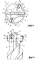
- the embodiment of a rotary impact twist drill shown in top view in FIG. 1 comprises a shank 1 with two main extraction grooves 4, 5 for drilling dust.
- the shaft 1 is equipped with a cutting plate 6, which is fixed in a groove 9 that extends over the diameter of the shaft 1, for example by soldering.
- the cutting plate 6 has roughly roof-shaped hard metal cutting edges 7, which axially withdraw from a cutting tip 8 rising above the end face 3 to the outside of the jacket 2 of the shaft 1.
- additional cutting edges 11 are arranged in the end face, the longitudinal axis L of which includes an acute angle with the longitudinal extension of the cutting plate 6.
- two additional cutting edges 11 are arranged diametrically opposite one another, their longitudinal axes L coinciding with a diameter of the shank 1. In this way, the cutting plate 6 and the additional cutting edges 11 essentially form the shape of an X. In the exemplary embodiment shown, the additional cutting edges 11 are arranged at the same distance from the center of the end face 3.
- the additional cutting edges 11 have a radial projection r relative to the jacket 2 of the shaft 1, which is greater than the radial projection s of the cutting insert 6.
- the radial projection of the cutting insert is at least 50% of the radial projection of the additional cutting edges.
- the additional cutting edges 11 define the enveloping circle H, which is indicated by dashed lines in FIG. 1.
- each additional cutting edge 11 is preceded by one of the main extraction grooves 4, 5.
- secondary extraction grooves 14, 15 for drilling dust are arranged, which preferably open into the main extraction grooves 4, 5 along the shaft 1.
- the axially parallel end faces 13 of the cutting plate 6 are curved.
- the curvature of the end faces 13 is matched to the curvature of the jacket 2 of the shaft 1 and is preferably part of a cylindrical surface.
- the axially parallel end faces 12 of the additional cutting edges 11 defining the enveloping circle H are preferably designed as cutting edges 22 in order to further increase their abrasive effect.
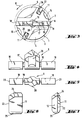
- FIGS. 4 and 5 show a further exemplary embodiment of a rotary impact twist drill according to the invention. It comprises a shaft 1 with two main discharge grooves 4, 5 for drilling dust and is at its one shaft end 10 with a cutting plate 6 equipped, which is segmented.
- the cutting plate 6 is divided into a central cutting edge 17 and into peripheral segments 18 which are connected to one another via narrow material webs 19, as is shown in more detail in FIGS. 4 and 5.
- the central cutting edge 17 projects beyond the peripheral segments 18 and has a cross-sectional thickening 20 in its central region.
- the groove 9, which extends over the diameter of the shank 1, has a recess 16 in the central region of the end face 3, which is designed to accommodate the thickened central region 20 of the cutting plate 6. In this way, the cutting plate 6 is positively fixed in the groove 9.
- the additional cutting edges 11 project beyond the peripheral segments 18 of the cutting plate both axially and radially.
- the distance between the additional cutting edges 11 and the raised area of the central cutting edge 17 is greater than the length of the thin material webs 19.
- the peripheral segments 18 only perform more guiding functions for the rotary impact twist drill.
- the actual cutting performance is taken over by the additional cutting edges 11 and, to a smaller extent, also by the central cutting edge 17. Since the cutting plate 6 and in particular the central cutting edge 17 in the segmented variant of the cutting plate shown for example are primarily exposed to axial loads from the axial blows on the tool, it is advantageous to produce the cutting plate 6 from an impact-resistant material.
- the additional cutting edges 11, which perform the actual mining performance and are subject to high abrasive forces, consist of a harder material than the cutting plate 6. In both cases, these are suitable hard metal alloys which are known per se from the prior art.
- the lateral end faces 13 of the cutting plate 6, or, in the case of the segmented cutting plate shown for example, the lateral end faces 23 of the peripheral segments 18 are curved.
- the end faces 23 are parts of a cylindrical surface, the curvature of which largely corresponds to the curvature of the jacket 2 of the shaft 1.
- an embodiment of an additional cutting edge 11 is shown in two side views. 7 is a front view from the direction of the free end face 12 of the additional cutting edge 11 which is in engagement with the borehole wall.
- the additional cutting edge 11 has approximately roof-shaped cutting edges 24. Its free end face 12 is also designed as a cutting edge 22 to make it abrasive To increase the effectiveness in use.
- the foot part 25 of the additional cutting edge is, for example, rounded and is in this way even better adapted to the shape of the base of the receiving groove 26 in the shaft 1.
- the receiving grooves 26 for the additional cutting edges as shown for example in FIGS. 1 and 3, are designed as separate grooves. In this way, the additional cutting edges 11 can be arranged independently of one another in their alignment with the cutting plate 6. However, it is also conceivable to arrange the additional cutting edges 11 in a single receiving groove 26 which extends over the diameter of the shaft 1 and to fix them there, for example by soldering.
- the additional cutting edges protrude axially or radially or both axially and radially from the peripheral regions of the cutting insert.
- the additional cutting edges thus take over the function of main cutting edges and experience the greatest shear stress when a borehole is created. Since the actual material removal takes place on the additional cutting edges, the broad main removal grooves for the drilling dust, in relation to the direction of rotation of the drilling tool, are located upstream of the additional cutting edges. In this way, the removed material is conveyed directly into the main discharge paths.
- the arrangement of the cutting insert and the additional cutting edges in the form of an X, in which the additional cutting edges leading with respect to the direction of rotation of the drilling tool with the subsequent cutting insert form an acute angle of less than 90 °, makes it possible to broaden the main procedures. This ensures even better removal of the drilling dust.
- the cutting edges of the insert only fulfill the guiding function for the rotary impact twist drill and can be further optimized with regard to their task.
Landscapes
- Engineering & Computer Science (AREA)
- Geology (AREA)
- Life Sciences & Earth Sciences (AREA)
- Mining & Mineral Resources (AREA)
- Physics & Mathematics (AREA)
- Environmental & Geological Engineering (AREA)
- Fluid Mechanics (AREA)
- Mechanical Engineering (AREA)
- General Life Sciences & Earth Sciences (AREA)
- Geochemistry & Mineralogy (AREA)
- Processing Of Stones Or Stones Resemblance Materials (AREA)
- Earth Drilling (AREA)
- Drilling Tools (AREA)
- Percussive Tools And Related Accessories (AREA)
Applications Claiming Priority (2)
| Application Number | Priority Date | Filing Date | Title |
|---|---|---|---|
| DE19545648 | 1995-12-07 | ||
| DE19545648A DE19545648A1 (de) | 1995-12-07 | 1995-12-07 | Drehschlag-Wendelbohrer |
Publications (3)
| Publication Number | Publication Date |
|---|---|
| EP0778391A2 true EP0778391A2 (fr) | 1997-06-11 |
| EP0778391A3 EP0778391A3 (fr) | 1998-07-01 |
| EP0778391B1 EP0778391B1 (fr) | 2003-08-20 |
Family
ID=7779439
Family Applications (1)
| Application Number | Title | Priority Date | Filing Date |
|---|---|---|---|
| EP96810657A Expired - Lifetime EP0778391B1 (fr) | 1995-12-07 | 1996-10-02 | Perceuse rotative hélicoidale à percussion |
Country Status (6)
| Country | Link |
|---|---|
| US (1) | US5836410A (fr) |
| EP (1) | EP0778391B1 (fr) |
| JP (1) | JP3819500B2 (fr) |
| CN (1) | CN1075431C (fr) |
| DE (2) | DE19545648A1 (fr) |
| DK (1) | DK0778391T3 (fr) |
Cited By (6)
| Publication number | Priority date | Publication date | Assignee | Title |
|---|---|---|---|---|
| EP1083294A1 (fr) * | 1999-09-09 | 2001-03-14 | HILTI Aktiengesellschaft | Outil de forage |
| EP1083293A1 (fr) * | 1999-09-09 | 2001-03-14 | HILTI Aktiengesellschaft | Outil de forage |
| EP1083295A1 (fr) * | 1999-09-09 | 2001-03-14 | HILTI Aktiengesellschaft | Outil de forage |
| US7258180B2 (en) | 2003-11-03 | 2007-08-21 | Illinois Tool Works Inc. | Rotary hammerdrill bit |
| AT13738U1 (de) * | 2013-03-05 | 2014-07-15 | Dywidag Systems Int Gmbh | Bohrkrone |
| US12070807B2 (en) | 2021-03-18 | 2024-08-27 | Black & Decker Inc. | One-piece cutting head for a drill bit |
Families Citing this family (25)
| Publication number | Priority date | Publication date | Assignee | Title |
|---|---|---|---|---|
| DE19703994B4 (de) * | 1997-02-03 | 2006-04-20 | Drebo Werkzeugfabrik Gmbh | Bohrer |
| DE19807394A1 (de) * | 1998-02-21 | 1999-08-26 | Hilti Ag | Bohr- und/oder Meisselwerkzeug |
| DE19811887A1 (de) * | 1998-03-18 | 1999-09-23 | Plica Werkzeugfabrik Ag Mollis | Hammerbohrwerkzeug |
| CN1081281C (zh) * | 1998-09-02 | 2002-03-20 | 王培林 | 钻头 |
| DE19860528B4 (de) * | 1998-12-30 | 2006-12-07 | Robert Bosch Gmbh | Gesteinsbohrer für Hammerbohrmaschinen |
| US6338390B1 (en) | 1999-01-12 | 2002-01-15 | Baker Hughes Incorporated | Method and apparatus for drilling a subterranean formation employing drill bit oscillation |
| DE29901285U1 (de) * | 1999-01-26 | 1999-06-17 | Plica Werkzeugfabrik Ag, Mollis | Bohrwerkzeug |
| DE19916975A1 (de) | 1999-04-15 | 2000-10-19 | Hilti Ag | Gesteinsbohrer |
| DE19964272C2 (de) * | 1999-09-16 | 2003-05-28 | Heller Dinklage Gmbh Geb | Bohrer, insbesondere Gesteinsbohrer |
| US6374931B1 (en) | 1999-11-03 | 2002-04-23 | Relton Corporation | Multiple cutter rotary hammer bit |
| DE10006936A1 (de) * | 2000-02-16 | 2001-08-23 | Hilti Ag | Bohrwerkzeug für Gestein |
| DE10006932A1 (de) * | 2000-02-16 | 2001-08-23 | Hilti Ag | Bohrwerkzeug für Gestein |
| DE10009732A1 (de) * | 2000-03-02 | 2001-09-06 | Hawera Probst Gmbh | Gesteinsbohrer |
| DE10053344A1 (de) * | 2000-10-27 | 2002-05-08 | Hilti Ag | Gesteinsbohrer |
| EP1302290B1 (fr) * | 2001-10-12 | 2008-07-02 | Robert Bosch Gmbh | Outil de forage |
| LU90862B1 (de) * | 2001-12-17 | 2003-06-18 | Cerametal Sarl | Schlag-oder Hammerbohrer |
| AU2003200561B9 (en) * | 2003-02-19 | 2009-07-02 | Sandvik Intellectual Property Ab | Drill bit |
| GB2404889A (en) * | 2003-08-12 | 2005-02-16 | Black & Decker Inc | A cutting plate for a drill bit |
| DE102006000201A1 (de) * | 2006-04-27 | 2007-10-31 | Hilti Ag | Hartstoffeinsatz |
| CN103419284A (zh) * | 2012-05-21 | 2013-12-04 | 博世电动工具(中国)有限公司 | 钻头 |
| EP2669033B1 (fr) | 2012-05-29 | 2015-11-04 | Black & Decker Inc. | Tête de coupe pour un foret. |
| CN104493263A (zh) * | 2014-09-28 | 2015-04-08 | 上海奥林汽车安全系统有限公司 | 一种高加工精度的双刃带麻花钻 |
| US9981406B2 (en) * | 2015-06-25 | 2018-05-29 | Black & Decker Inc. | Drill bit |
| DE102016000899A1 (de) | 2016-01-28 | 2017-08-03 | Universität Kassel | Schneidwerkzeug für die spanende Bearbeitung eines Werkstückes |
| US10507534B2 (en) | 2016-03-17 | 2019-12-17 | O-Tags, Inc. | Systems, methods, and apparatus for reliably installing survey tags |
Family Cites Families (8)
| Publication number | Priority date | Publication date | Assignee | Title |
|---|---|---|---|---|
| US2099677A (en) * | 1936-03-19 | 1937-11-23 | John P Cunningham | Rock or earth drill bit |
| US2529788A (en) * | 1948-07-06 | 1950-11-14 | Carl A Signell | Drill |
| DE2414354A1 (de) * | 1974-03-26 | 1975-10-16 | Heller Geb | Gesteinsbohrer |
| DE3707798A1 (de) * | 1987-03-11 | 1988-09-22 | Hawera Probst Kg Hartmetall | Gesteinsbohrer |
| DE3742661A1 (de) * | 1987-12-16 | 1989-07-13 | Hawera Probst Kg Hartmetall | Gesteinsbohrer |
| DE3820695C2 (de) * | 1988-06-18 | 1996-07-25 | Hawera Probst Kg Hartmetall | Gesteinsbohrer |
| DE4306981A1 (de) * | 1993-03-05 | 1994-09-08 | Keil Werkzeugfabrik Karl Eisch | Bohrer für Gestein oder dergleichen |
| DE4407119A1 (de) * | 1993-12-11 | 1995-06-14 | Hawera Probst Kg Hartmetall | Gesteinsbohrer |
-
1995
- 1995-12-07 DE DE19545648A patent/DE19545648A1/de not_active Ceased
-
1996
- 1996-10-02 EP EP96810657A patent/EP0778391B1/fr not_active Expired - Lifetime
- 1996-10-02 DE DE59610671T patent/DE59610671D1/de not_active Expired - Lifetime
- 1996-10-02 DK DK96810657T patent/DK0778391T3/da active
- 1996-11-25 CN CN96121810A patent/CN1075431C/zh not_active Expired - Fee Related
- 1996-12-06 JP JP32697796A patent/JP3819500B2/ja not_active Expired - Fee Related
- 1996-12-09 US US08/762,173 patent/US5836410A/en not_active Expired - Lifetime
Cited By (9)
| Publication number | Priority date | Publication date | Assignee | Title |
|---|---|---|---|---|
| EP1083294A1 (fr) * | 1999-09-09 | 2001-03-14 | HILTI Aktiengesellschaft | Outil de forage |
| EP1083293A1 (fr) * | 1999-09-09 | 2001-03-14 | HILTI Aktiengesellschaft | Outil de forage |
| EP1083295A1 (fr) * | 1999-09-09 | 2001-03-14 | HILTI Aktiengesellschaft | Outil de forage |
| US6405813B1 (en) | 1999-09-09 | 2002-06-18 | Hilti Aktiengesellschaft | Rock drill for drilling bores in reinforced concrete |
| US6431295B1 (en) | 1999-09-09 | 2002-08-13 | Hilti Aktiengesellschaft | Rock drill |
| US6450273B1 (en) | 1999-09-09 | 2002-09-17 | Hilti Aktiengesellschaft | Drilling tool including drilling head with multiple cutting members separated drilled material grooves |
| US7258180B2 (en) | 2003-11-03 | 2007-08-21 | Illinois Tool Works Inc. | Rotary hammerdrill bit |
| AT13738U1 (de) * | 2013-03-05 | 2014-07-15 | Dywidag Systems Int Gmbh | Bohrkrone |
| US12070807B2 (en) | 2021-03-18 | 2024-08-27 | Black & Decker Inc. | One-piece cutting head for a drill bit |
Also Published As
| Publication number | Publication date |
|---|---|
| DK0778391T3 (da) | 2003-12-15 |
| DE59610671D1 (de) | 2003-09-25 |
| CN1075431C (zh) | 2001-11-28 |
| DE19545648A1 (de) | 1997-06-12 |
| JPH09177465A (ja) | 1997-07-08 |
| EP0778391A3 (fr) | 1998-07-01 |
| US5836410A (en) | 1998-11-17 |
| EP0778391B1 (fr) | 2003-08-20 |
| CN1154900A (zh) | 1997-07-23 |
| JP3819500B2 (ja) | 2006-09-06 |
Similar Documents
| Publication | Publication Date | Title |
|---|---|---|
| EP0778391B1 (fr) | Perceuse rotative hélicoidale à percussion | |
| EP0884448B1 (fr) | Trépan de roche avec rainures d'évacuation hélicoidales | |
| EP0778100B1 (fr) | Foret héliocoidal de percussion | |
| DE19780282B3 (de) | Freitragend ausgebildeter Erweiterungsbohrer | |
| EP1045112B1 (fr) | Broche à pierre | |
| EP0878261B1 (fr) | Outil de forage | |
| DE3820695C2 (de) | Gesteinsbohrer | |
| DE3407427A1 (de) | Bohrkrone | |
| EP0846835A2 (fr) | Trépan de forage du béton ou de la roche avec rainures d'évacuation hélicoidales | |
| EP0937860B1 (fr) | Outil de forage et ou de frappe | |
| EP1083294B1 (fr) | Outil de forage | |
| EP0655547A2 (fr) | Trépan de roche avec partie transporteuse hélicoidale | |
| EP1083295B1 (fr) | Outil de forage | |
| EP2105574B1 (fr) | Utilisation d'une arête coupante | |
| EP1125662A2 (fr) | Foret à forer de la pierre | |
| EP2199531A2 (fr) | Tête de forage pour foret à pierre | |
| EP1083293B1 (fr) | Outil de forage | |
| EP0778390B1 (fr) | Perceuse rotative hélicoidale à percussion | |
| DE10161009C2 (de) | Schrämwerkzeug mit Verschleißschutzhülse | |
| DE2423510A1 (de) | Gesteinsbohrer | |
| DE2841679A1 (de) | Auswechselbare bohrkrone fuer einen bei allen gesteinsarten anwendbaren gesteindrehschlagbohrer und bohrhammer | |
| EP0965406B1 (fr) | Outil de forage | |
| EP0965405B1 (fr) | Outil de forage | |
| DE3630444A1 (de) | Abtragvorrichtung fuer schneidenden materialabtrag | |
| CH619027A5 (en) | Drilling appliance with an interchangeable rock drill, in particular a percussion drill, a hammer drill and the like |
Legal Events
| Date | Code | Title | Description |
|---|---|---|---|
| PUAI | Public reference made under article 153(3) epc to a published international application that has entered the european phase |
Free format text: ORIGINAL CODE: 0009012 |
|
| AK | Designated contracting states |
Kind code of ref document: A2 Designated state(s): CH DE DK FR GB IT LI SE |
|
| PUAL | Search report despatched |
Free format text: ORIGINAL CODE: 0009013 |
|
| AK | Designated contracting states |
Kind code of ref document: A3 Designated state(s): CH DE DK FR GB IT LI SE |
|
| 17P | Request for examination filed |
Effective date: 19990104 |
|
| 17Q | First examination report despatched |
Effective date: 20011121 |
|
| GRAH | Despatch of communication of intention to grant a patent |
Free format text: ORIGINAL CODE: EPIDOS IGRA |
|
| GRAH | Despatch of communication of intention to grant a patent |
Free format text: ORIGINAL CODE: EPIDOS IGRA |
|
| GRAA | (expected) grant |
Free format text: ORIGINAL CODE: 0009210 |
|
| AK | Designated contracting states |
Designated state(s): CH DE DK FR GB IT LI SE |
|
| REG | Reference to a national code |
Ref country code: GB Ref legal event code: FG4D Free format text: NOT ENGLISH |
|
| REG | Reference to a national code |
Ref country code: CH Ref legal event code: EP |
|
| REG | Reference to a national code |
Ref country code: SE Ref legal event code: TRGR |
|
| REF | Corresponds to: |
Ref document number: 59610671 Country of ref document: DE Date of ref document: 20030925 Kind code of ref document: P |
|
| GBT | Gb: translation of ep patent filed (gb section 77(6)(a)/1977) |
Effective date: 20031027 |
|
| REG | Reference to a national code |
Ref country code: DK Ref legal event code: T3 |
|
| ET | Fr: translation filed | ||
| PLBE | No opposition filed within time limit |
Free format text: ORIGINAL CODE: 0009261 |
|
| STAA | Information on the status of an ep patent application or granted ep patent |
Free format text: STATUS: NO OPPOSITION FILED WITHIN TIME LIMIT |
|
| 26N | No opposition filed |
Effective date: 20040524 |
|
| PGFP | Annual fee paid to national office [announced via postgrant information from national office to epo] |
Ref country code: DK Payment date: 20081013 Year of fee payment: 13 Ref country code: CH Payment date: 20081016 Year of fee payment: 13 |
|
| PGFP | Annual fee paid to national office [announced via postgrant information from national office to epo] |
Ref country code: IT Payment date: 20081028 Year of fee payment: 13 Ref country code: SE Payment date: 20081022 Year of fee payment: 13 |
|
| REG | Reference to a national code |
Ref country code: CH Ref legal event code: PL |
|
| EUG | Se: european patent has lapsed | ||
| REG | Reference to a national code |
Ref country code: DK Ref legal event code: EBP |
|
| PG25 | Lapsed in a contracting state [announced via postgrant information from national office to epo] |
Ref country code: LI Free format text: LAPSE BECAUSE OF NON-PAYMENT OF DUE FEES Effective date: 20091031 Ref country code: CH Free format text: LAPSE BECAUSE OF NON-PAYMENT OF DUE FEES Effective date: 20091031 |
|
| PG25 | Lapsed in a contracting state [announced via postgrant information from national office to epo] |
Ref country code: DK Free format text: LAPSE BECAUSE OF NON-PAYMENT OF DUE FEES Effective date: 20091031 |
|
| PG25 | Lapsed in a contracting state [announced via postgrant information from national office to epo] |
Ref country code: IT Free format text: LAPSE BECAUSE OF NON-PAYMENT OF DUE FEES Effective date: 20091002 |
|
| PG25 | Lapsed in a contracting state [announced via postgrant information from national office to epo] |
Ref country code: SE Free format text: LAPSE BECAUSE OF NON-PAYMENT OF DUE FEES Effective date: 20091003 |
|
| PGFP | Annual fee paid to national office [announced via postgrant information from national office to epo] |
Ref country code: GB Payment date: 20141001 Year of fee payment: 19 Ref country code: FR Payment date: 20141008 Year of fee payment: 19 Ref country code: DE Payment date: 20140923 Year of fee payment: 19 |
|
| REG | Reference to a national code |
Ref country code: DE Ref legal event code: R119 Ref document number: 59610671 Country of ref document: DE |
|
| GBPC | Gb: european patent ceased through non-payment of renewal fee |
Effective date: 20151002 |
|
| PG25 | Lapsed in a contracting state [announced via postgrant information from national office to epo] |
Ref country code: GB Free format text: LAPSE BECAUSE OF NON-PAYMENT OF DUE FEES Effective date: 20151002 Ref country code: DE Free format text: LAPSE BECAUSE OF NON-PAYMENT OF DUE FEES Effective date: 20160503 |
|
| REG | Reference to a national code |
Ref country code: FR Ref legal event code: ST Effective date: 20160630 |
|
| PG25 | Lapsed in a contracting state [announced via postgrant information from national office to epo] |
Ref country code: FR Free format text: LAPSE BECAUSE OF NON-PAYMENT OF DUE FEES Effective date: 20151102 |