EP0778414A2 - Diagnosesystem für Kondensatorzündsysteme - Google Patents
Diagnosesystem für Kondensatorzündsysteme Download PDFInfo
- Publication number
- EP0778414A2 EP0778414A2 EP96111406A EP96111406A EP0778414A2 EP 0778414 A2 EP0778414 A2 EP 0778414A2 EP 96111406 A EP96111406 A EP 96111406A EP 96111406 A EP96111406 A EP 96111406A EP 0778414 A2 EP0778414 A2 EP 0778414A2
- Authority
- EP
- European Patent Office
- Prior art keywords
- storage capacitor
- circuit means
- circuit
- voltage
- primary
- Prior art date
- Legal status (The legal status is an assumption and is not a legal conclusion. Google has not performed a legal analysis and makes no representation as to the accuracy of the status listed.)
- Granted
Links
Images


Classifications
-
- F—MECHANICAL ENGINEERING; LIGHTING; HEATING; WEAPONS; BLASTING
- F02—COMBUSTION ENGINES; HOT-GAS OR COMBUSTION-PRODUCT ENGINE PLANTS
- F02P—IGNITION, OTHER THAN COMPRESSION IGNITION, FOR INTERNAL-COMBUSTION ENGINES; TESTING OF IGNITION TIMING IN COMPRESSION-IGNITION ENGINES
- F02P17/00—Testing of ignition installations, e.g. in combination with adjusting; Testing of ignition timing in compression-ignition engines
- F02P17/12—Testing characteristics of the spark, ignition voltage or current
-
- F—MECHANICAL ENGINEERING; LIGHTING; HEATING; WEAPONS; BLASTING
- F02—COMBUSTION ENGINES; HOT-GAS OR COMBUSTION-PRODUCT ENGINE PLANTS
- F02P—IGNITION, OTHER THAN COMPRESSION IGNITION, FOR INTERNAL-COMBUSTION ENGINES; TESTING OF IGNITION TIMING IN COMPRESSION-IGNITION ENGINES
- F02P3/00—Other installations
- F02P3/06—Other installations having capacitive energy storage
- F02P3/08—Layout of circuits
- F02P3/0807—Closing the discharge circuit of the storage capacitor with electronic switching means
- F02P3/0838—Closing the discharge circuit of the storage capacitor with electronic switching means with semiconductor devices
Definitions
- This invention relates to capacitive discharge ignition systems for industrial internal combustion engines wherein the charge on a capacitor is switched to a spark plug circuit.
- This invention has particular application to ignition systems for stationary engines fueled by the natural gas which is being pumped by pumps driven by the engines.
- the invention may relate to low tension ignition systems wherein a coil is associated with each spark plug located close to the spark plug.
- This invention may further involve distribution from a single capacitor to two or more spark plugs. It may further involve the use of more than one capacitor to allow for complete charging between discharges. It further may involve magnetic pickup pulses attached to the flywheel of an internal combustion engine for generating trigger pulses for causing discharge of the capacitor or capacitors to the spark plug circuit.
- the secondary (and primary) diagnostic function uses the measured voltage of the storage capacitor to capture discharge time to detect the presence of certain conditions requiring attention and generates the appropriate diagnostic messages.
- United States Patent No. 5,208,540 entitled “Ignition Performance Monitor and Monitoring Method for Capacitive Discharge Ignition Systems” uses electrical current sensing on the primary side of a low tension capacitive discharge ignition system to determine the time period during which current generated in the primary winding takes to decay to zero and uses this to calculate and indicate the firing voltage to fire a given spark plug.
- this patent makes no disclosure for a means to detect an open primary, a primary shortage, a capacitor not charged, an open secondary or a shorted secondary.
- a capacitive discharge ignition system having at least one spark plug circuit comprising at least one each storage capacitor, ignition coil and spark plug and electrical connections therebetween.
- the energy stored on the storage capacitor is, in response to a trigger pulse, switched to the primary side of the ignition coil to induce high voltage in the secondary side of the ignition coil to generate a spark in the spark plug connected in series with the secondary side of the ignition coil.
- the diagnostic system for this ignition system comprises a circuit for detecting the voltage on the storage capacitor crossing through a first threshold, for example, near 80% of full charge voltage, for marking the onset of discharge of the storage capacitor and generating a first pulse.
- the diagnostic circuit further comprises a circuit for detecting the voltage across the storage capacitor crossing through a second voltage, for example, near zero, for marking the substantially complete discharge of the storage capacitor and generating a second pulse.
- a third circuit includes a counter and a clock pulse generator. The counter is responsive to the transition edge of the first and second digital pulses, respectively, for starting and stopping the counter counting pulses delivered by the clock pulse generator.
- a state machine generates the trigger pulse for discharging the capacitor. Signals move the count accumulated out of the counter and reset the counter prior to the next trigger pulse.
- a fourth circuit comprising a microprocessor programmed for analyzing the count accumulated by the counter and transferred to the microprocessor, diagnoses the condition of the spark plug circuit.
- the diagnosis also includes detecting at least one of the following conditions: open primary, shorted primary, no spark and storage capacitor not charged. It is especially preferred, according to this invention, that the first circuit for detecting the first threshold detects a voltage threshold relative to the fully charged voltage so that the effect of the varying charge voltages necessary for adjustable spark energy can be accommodated. It is noted that the charge voltage on the storage capacitor may be either positive or negative with respect to ground.
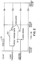
- a storage capacitor 10 is charged by a power supply 11.
- the power supply may comprise a DC-to-DC converter for stepping up a typical 12 or 24 volt input to a voltage typically of about 180 (100-400).
- a solid state switch 12 is positioned between the primary winding 13A of coil 13 and the storage capacitor. The switch is arranged for discharging the capacitor 10 upon application of a trigger pulse on line 18 provided by a state machine 15.
- the secondary winding 13B of the coil 13 is in series with the spark plug 14. Discharge of the energy on the capacitor 10 through solid state switch 12 to the primary winding 13A of the coil 13 creates yet a higher voltage in the secondary winding 13A of the coil 13 for generating a spark in the spark plug 14.
- the state machine 15 is responsive to pulses from pickups 16 and 17. These pulses typically comprise one generated on each revolution of the flywheel by pickup 16 and a plurality of pulses generated by pickup 17 each associated with one of the cylinders of the internal combustion engine. Typically, the pickup pulses are magnetically generated. Other arrangements known to those skilled in the art may also be employed.
- threshold circuit 19 detects the start of discharge of the storage capacitor and threshold circuit 20 detects the end of discharge.
- Each threshold circuit generates a high going pulse which is applied to the start and stop inputs of the counter 21.
- clock pulses from clock 22 are counted in a register in counter 21.
- the count in the counter register is transferred to an output register in the counter 21.
- the trigger pulse generated by the state machine transfers the count to the output register.
- the digital computer 23 initiates a read signal to the counter output register which transfers the count in the output register on bus 24 to the digital computer where the count can be analyzed.
- the first threshold signal 30 goes high a short time after the trigger pulse and remains high until the storage capacitor is recharged.
- the second threshold signal 31 goes high at approximately the time the storage capacitor is fully discharged and remains high until recharge of the storage capacitor.
- the count 32 is recorded in the counter.
- the count is transferred to an output register of the counter. Thereafter, on application of a read and reset signal applied to the counter, the output is transferred to the digital computer.
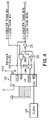
- Fig. 3 there is shown a detailed circuit diagram of a preferred embodiment of threshold circuits according to this invention.
- the voltage on the storage capacitor is applied at point A.
- the circuit between point A and point B is the second threshold circuit or the zero crossing detection circuit.
- the voltage on the storage capacitor is divided by resistors R1 and R2 and applied to inverter I1 which has an input threshold near zero volts. When the voltage on the storage capacitor discharges to near zero, the threshold is crossed and the output of the inverter goes high.
- the circuit elements between point A and point C comprise the first threshold circuit for detecting the initiation of discharge of the storage capacitor.
- Diode D1 and capacitor C1 capture and temporarily hold the fully charged voltage of the storage capacitor which is applied across a voltage divider comprising resistors R3 and R4.
- the fractional voltage across R4 is then applied to the noninverting input of a differential amplifier U1.
- the instantaneous voltage of the storage capacitor is applied across the voltage divider comprised of resistors R5, R6 and potentiometer P1.
- the divided voltage across R6 and P1 is applied to the inverting input of differential amplifier U1.
- the fractional voltage at the junction of R5 and R6 will be greater than the fractional voltage at the junction of resistors R3 and R4.
- the output is pulled low and the inverter I2 generates a high output pulse at C.
- Adjustment of the potentiometer permits for adjustment of the fractional value of storage capacitor voltage which must be reached to cause the first threshold circuit to go high.
- the counter U2 is, according to this preferred embodiment, a high speed CMOS eight-bit counter/register fabricated with silicon gauge CMOS technology.
- the manufacture's number is TC74HC590A.
- the internal counter counts on the positive going edge of the counter clock (CCK) when counter clock enable ( CCKEN ⁇ ) is low.
- the counter clear ( CCLR ⁇ ) is low, the internal counter is cleared asynchronously to the clock.
- the data in the internal counter is loaded into the output register at the positive going edge of the register clock (RCK) and the registered outputs are controlled by enable input ( G ⁇ ).
- Ripple carry out from the eight-bit counter register is at output ( RCO ⁇ ).
- the first threshold input is applied at C and inverted through inverter I5 and applied to or gate OR, the output of which is applied to the counter clock enable input ( CCKEN ⁇ ).
- the carry out from the counter ( RCO ⁇ ) is applied to the other input of the or gate OR through an inverter I6.
- the second threshold is applied at B to an AND gate along with the ripple carry out from the counter chip.
- the trigger pulse applied at D causes the count to be transferred to the output register.
- the first threshold signal at C goes low and when applied to the clear input ( CCLR ⁇ ) of the counter, clears all registers.
- the electronic hardware is used to create two time-critical digital waveforms based on the storage capacitor voltage as it discharges through the ignition coil.
- the first digital signal moves from low to high state when the capacitor voltage falls below 80%, for example, of its charged state as a result of the firing. When the capacitor gets recharged, the signal moves back to a low state. This signal is referred to as the first threshold or 80% signal.
- the second digital signal moves from a low to a high state when the capacitor is essentially fully discharged due to firing. This transition occurs when the capacitor falls below about two volts. When the capacitor gets recharged and its voltage rises again above two volts, this signal moves back to a low state. This signal is referred to as the second threshold signal or the zero crossing signal.
- a counter having a fixed frequency input is used to measure the time between the rising edge of the 80% signal and the rising edge of the zero crossing signal. The resulting counts provide a time measurement which is the basis of the diagnostics explained hereafter.
- the low state of the 80% signal indicates the capacitor is charged. The low signal activates the counter clear function which holds the counter at zero whenever the 80% signal is low.
- a fire or trigger pulse is generated by the ignition state machine when a spark plug firing is desired.
- the rising edge of this fire pulse is also used to clock the counter data into the output register to enhance the capabilities of the diagnostics.
- the capacitor is charged and the counter is held at zero when the fire pulse occurs.
- a normal firing causes a high signal on the 80% signal which allows the counter to begin counting.
- the zero crossing signal moves high and clocks the appropriate count into the output register. This count represents the time between the rising edges of the 80% signal and the zero crossing signal.
- the counter will have data of 255 to be clocked into the output register. This occurs because the 80% line remained high, permitting the counter to count until it was jammed by the ripple carry out. This leaves 255 counts rather than zero counts to be clocked into the output register when the fire pulse comes. This allows the system to identify a failure to fire because of a discharged capacitor. If the ignition tries to fire an open primary output, the 80% signal and the zero crossing signal do not move high and the only data clocked into the output register is the zero value which was clocked by the fire pulse. This enables the system to identify an open primary.
- the count value is read from the counter output register for every firing just prior to the next firing. This read is timed by the ignition state machine logic and is written to an array in a dual-port RAM, for example.
- the dual-port RAM is then read and analyzed from the other port by the microprocessor one time per engine cycle. With this system, the microprocessor can test data from every single firing against the thresholds which trip the diagnostics with only a limited amount of overhead. This entire task can be performed in real time by a microprocessor as well.
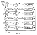
- FIG. 5 there is shown a flow diagram for a computer program that performs the diagnosis.
- the program is entered at 50.
- the count is tested for being less than 1 . If yes, the previous count is tested for being less than 1 . If both yes, the primary open flag is set at 53. If otherwise, at 54 the count is tested to determine if it is less than 30 and if yes, the previous count is likewise tested. If both counts are less than 30 , the primary shorted flag is set at 56. If otherwise, then at 57 the count is tested for greater than about 60 . If yes, the previous count is tested for greater than about 60 . If both are yes, then the low secondary voltage spark flag is set at 59.
- the count is tested at 60 for being greater than 254 . If yes, and the previous count was greater than 254 , the capacitor not charged flag is set at 62. If otherwise, the count is tested at 63 for greater than about 130 . If yes, the previous count is tested for the same and if both are yes, then the no secondary spark or open secondary flag is set at 65. If otherwise, the count is tested at 66 for greater than about 90 . If yes, the previous count is likewise tested and if both are yes, the high secondary spark voltage flag is set at 68. By reference to these flags, the computer can output a digital display indicating the fault condition.
Landscapes
- Engineering & Computer Science (AREA)
- Chemical & Material Sciences (AREA)
- Combustion & Propulsion (AREA)
- Mechanical Engineering (AREA)
- General Engineering & Computer Science (AREA)
- Ignition Installations For Internal Combustion Engines (AREA)
- Air Bags (AREA)
- Testing Electric Properties And Detecting Electric Faults (AREA)
Applications Claiming Priority (2)
| Application Number | Priority Date | Filing Date | Title |
|---|---|---|---|
| US568492 | 1990-08-16 | ||
| US08/568,492 US5623209A (en) | 1995-12-07 | 1995-12-07 | Diagnostic system for capacitive discharge ignition system |
Publications (3)
| Publication Number | Publication Date |
|---|---|
| EP0778414A2 true EP0778414A2 (de) | 1997-06-11 |
| EP0778414A3 EP0778414A3 (de) | 1999-02-03 |
| EP0778414B1 EP0778414B1 (de) | 2003-03-05 |
Family
ID=24271526
Family Applications (1)
| Application Number | Title | Priority Date | Filing Date |
|---|---|---|---|
| EP96111406A Expired - Lifetime EP0778414B1 (de) | 1995-12-07 | 1996-07-16 | Diagnosesystem für Kondensatorzündsysteme |
Country Status (4)
| Country | Link |
|---|---|
| US (1) | US5623209A (de) |
| EP (1) | EP0778414B1 (de) |
| AT (1) | ATE233866T1 (de) |
| DE (1) | DE69626471T2 (de) |
Families Citing this family (14)
| Publication number | Priority date | Publication date | Assignee | Title |
|---|---|---|---|---|
| US6163088A (en) * | 1999-09-30 | 2000-12-19 | Caterpillar Inc. | Method and apparatus for providing standby power from a generator using capacitor supplied voltage |
| DE10003109A1 (de) * | 2000-01-26 | 2001-08-02 | Bosch Gmbh Robert | Verfahren zur Erzeugung einer Folge von Hochspannungszündfunken und Hochspannungszündvorrichtung |
| US6384606B1 (en) | 2000-03-06 | 2002-05-07 | Sn Controls Llc | Ignition coil with lead for secondary diagnostics |
| US6600322B1 (en) | 2000-03-06 | 2003-07-29 | Murphy Power Ignition | Stroke distinction in 4-cycle engines without a cam reference |
| US6492818B1 (en) | 2000-11-06 | 2002-12-10 | Cummins, Inc. | Apparatus and method for determining component fault conditions as a function of primary coil voltage in a capacitive discharge ignition system |
| US6662639B1 (en) * | 2002-09-06 | 2003-12-16 | Spx Corporation | Secondary ignition pickup and method |
| US7251571B2 (en) * | 2003-09-05 | 2007-07-31 | Visteon Global Technologies, Inc. | Methods of diagnosing open-secondary winding of an ignition coil using the ionization current signal |
| JP4188788B2 (ja) * | 2003-09-25 | 2008-11-26 | 三菱電機株式会社 | 容量放電点火装置 |
| FI123042B (fi) | 2009-08-28 | 2012-10-15 | Waertsilae Finland Oy | Kipinäsytytteisen mäntäpolttomoottorin sytytyssäätö |
| CN102059681A (zh) * | 2010-08-20 | 2011-05-18 | 朱益民 | 一种燃气钉枪高压放电检测保护方法、电路及燃气钉枪 |
| CN102825580B (zh) * | 2012-09-18 | 2015-04-15 | 温州市协力射钉紧固器材厂 | 带有计数、电量显示集成的瓦斯射钉器系统 |
| JP5901718B1 (ja) * | 2014-09-24 | 2016-04-13 | 三菱電機株式会社 | 内燃機関制御装置 |
| RU2614388C2 (ru) * | 2015-09-14 | 2017-03-27 | Акционерное общество "Уфимское научно-производственное предприятие "Молния" | Устройство контроля емкостной системы зажигания двигателей летательных аппаратов |
| JP6643144B2 (ja) * | 2016-02-29 | 2020-02-12 | 株式会社Soken | 点火回路の故障診断装置 |
Family Cites Families (14)
| Publication number | Priority date | Publication date | Assignee | Title |
|---|---|---|---|---|
| US3784901A (en) * | 1972-12-22 | 1974-01-08 | Electro Specialties Inc | Capacitor discharge ignition system testing apparatus |
| US4186337A (en) * | 1977-12-12 | 1980-01-29 | K-D Manufacturing Company | Analyzer for transistor ignition system |
| DE3065662D1 (en) * | 1979-05-25 | 1983-12-29 | Lucas Ind Plc | Apparatus for use in testing an internal combustion engine ignition system |
| GB8522600D0 (en) * | 1985-09-12 | 1985-10-16 | Ti Crypton Ltd | Engine analysers |
| JPS63285265A (ja) * | 1987-05-15 | 1988-11-22 | Mitsubishi Electric Corp | 内燃機関点火装置 |
| US5216369A (en) * | 1989-02-22 | 1993-06-01 | Nippondenso Co., Ltd. | Ignition occurrence detecting device for use in an ignition apparatus |
| DE4009451C2 (de) * | 1989-03-27 | 1995-02-16 | Mitsubishi Electric Corp | Zündvorrichtung für eine Brennkraftmaschine |
| DE3928726A1 (de) * | 1989-08-30 | 1991-03-07 | Vogt Electronic Ag | Zuendsystem mit stromkontrollierter halbleiterschaltung |
| US5054461A (en) * | 1990-12-31 | 1991-10-08 | Motorola, Inc. | Ionization control for automotive ignition system |
| JP2678986B2 (ja) * | 1991-03-07 | 1997-11-19 | 本田技研工業株式会社 | 内燃機関の失火検出装置 |
| US5221904A (en) * | 1991-03-07 | 1993-06-22 | Honda Giken Kogyo Kabushiki Kaisha | Misfire-detecting system for internal combustion engines |
| US5208540A (en) * | 1992-02-28 | 1993-05-04 | Coltec Industries Inc. | Ignition performance monitor and monitoring method for capacitive discharge ignition systems |
| JP3341349B2 (ja) * | 1993-04-14 | 2002-11-05 | 株式会社デンソー | 素子の劣化検出装置 |
| US5572135A (en) * | 1993-12-27 | 1996-11-05 | Simmonds Precision Engine Systems | Diagnostic apparatus and methods for ignition circuits |
-
1995
- 1995-12-07 US US08/568,492 patent/US5623209A/en not_active Expired - Lifetime
-
1996
- 1996-07-16 DE DE69626471T patent/DE69626471T2/de not_active Expired - Lifetime
- 1996-07-16 AT AT96111406T patent/ATE233866T1/de not_active IP Right Cessation
- 1996-07-16 EP EP96111406A patent/EP0778414B1/de not_active Expired - Lifetime
Also Published As
| Publication number | Publication date |
|---|---|
| EP0778414B1 (de) | 2003-03-05 |
| DE69626471T2 (de) | 2003-12-18 |
| EP0778414A3 (de) | 1999-02-03 |
| US5623209A (en) | 1997-04-22 |
| ATE233866T1 (de) | 2003-03-15 |
| DE69626471D1 (de) | 2003-04-10 |
Similar Documents
| Publication | Publication Date | Title |
|---|---|---|
| EP0778414B1 (de) | Diagnosesystem für Kondensatorzündsysteme | |
| US6766243B1 (en) | Device and method for ignition in an internal combustion engine | |
| JP2732971B2 (ja) | ガソリン機関の失火検出装置 | |
| US4394742A (en) | Engine generated waveform analyzer | |
| US3972230A (en) | Detecting malfunction in cylinders of internal combustion engines | |
| US4812979A (en) | Method and apparatus for analyzing the performance of the electronic ignition of an internal combustion engine | |
| US5283527A (en) | Methods and apparatus for detecting short circuited secondary coil winding via monitoring primary coil winding | |
| JPS61155753A (ja) | 内燃機関点火装置内イオン化電流検知用方法及び装置 | |
| US4333054A (en) | Apparatus for use in testing an internal combustion engine ignition system | |
| EP0138157A1 (de) | Ruhender Leonardsatz | |
| EP0810369A2 (de) | Vorzündungserkennungsmethode | |
| US6492818B1 (en) | Apparatus and method for determining component fault conditions as a function of primary coil voltage in a capacitive discharge ignition system | |
| DE4303030A1 (de) | ||
| US6752004B2 (en) | Misfire detection apparatus for internal combustion engine | |
| CA1050111A (en) | Vehicle rpm and dwell measurement system | |
| DE10257383B4 (de) | Fehlzündungs-Detektionsgerät für einen Verbrennungsmotor | |
| US3986009A (en) | Power contribution measurement system for internal combustion engines | |
| US2263859A (en) | Spark advance indicator | |
| US6948484B2 (en) | Capacitor discharge ignition device | |
| EP0020067A1 (de) | Apparat zum Prüfen der elektronischen Zündanlagen von Brennkraftmaschinen | |
| EP0615582A1 (de) | Zündanlage für brennkraftmaschinen. | |
| US4000456A (en) | Engine diagnostic apparatus | |
| JP2665794B2 (ja) | 内燃機関の点火装置 | |
| US4673883A (en) | Automatically scaled engine diagnostic apparatus | |
| JPH02504307A (ja) | 内燃エンジンにおけるノツキングを検出する方法 |
Legal Events
| Date | Code | Title | Description |
|---|---|---|---|
| PUAI | Public reference made under article 153(3) epc to a published international application that has entered the european phase |
Free format text: ORIGINAL CODE: 0009012 |
|
| AK | Designated contracting states |
Kind code of ref document: A2 Designated state(s): AT BE DE FR GB IT LU NL |
|
| PUAL | Search report despatched |
Free format text: ORIGINAL CODE: 0009013 |
|
| AK | Designated contracting states |
Kind code of ref document: A3 Designated state(s): AT BE DE FR GB IT LU NL |
|
| 17P | Request for examination filed |
Effective date: 19990720 |
|
| GRAG | Despatch of communication of intention to grant |
Free format text: ORIGINAL CODE: EPIDOS AGRA |
|
| 17Q | First examination report despatched |
Effective date: 20020611 |
|
| GRAG | Despatch of communication of intention to grant |
Free format text: ORIGINAL CODE: EPIDOS AGRA |
|
| GRAG | Despatch of communication of intention to grant |
Free format text: ORIGINAL CODE: EPIDOS AGRA |
|
| GRAH | Despatch of communication of intention to grant a patent |
Free format text: ORIGINAL CODE: EPIDOS IGRA |
|
| GRAH | Despatch of communication of intention to grant a patent |
Free format text: ORIGINAL CODE: EPIDOS IGRA |
|
| GRAA | (expected) grant |
Free format text: ORIGINAL CODE: 0009210 |
|
| AK | Designated contracting states |
Designated state(s): AT BE DE FR GB IT LU NL |
|
| PG25 | Lapsed in a contracting state [announced via postgrant information from national office to epo] |
Ref country code: IT Free format text: LAPSE BECAUSE OF FAILURE TO SUBMIT A TRANSLATION OF THE DESCRIPTION OR TO PAY THE FEE WITHIN THE PRE;WARNING: LAPSES OF ITALIAN PATENTS WITH EFFECTIVE DATE BEFORE 2007 MAY HAVE OCCURRED AT ANY TIME BEFORE 2007. THE CORRECT EFFECTIVE DATE MAY BE DIFFERENT FROM THE ONE RECORDED.SCRIBED TIME-LIMIT Effective date: 20030305 Ref country code: FR Free format text: LAPSE BECAUSE OF NON-PAYMENT OF DUE FEES Effective date: 20030305 Ref country code: BE Free format text: LAPSE BECAUSE OF FAILURE TO SUBMIT A TRANSLATION OF THE DESCRIPTION OR TO PAY THE FEE WITHIN THE PRESCRIBED TIME-LIMIT Effective date: 20030305 Ref country code: AT Free format text: LAPSE BECAUSE OF FAILURE TO SUBMIT A TRANSLATION OF THE DESCRIPTION OR TO PAY THE FEE WITHIN THE PRESCRIBED TIME-LIMIT Effective date: 20030305 |
|
| REG | Reference to a national code |
Ref country code: GB Ref legal event code: FG4D |
|
| REF | Corresponds to: |
Ref document number: 69626471 Country of ref document: DE Date of ref document: 20030410 Kind code of ref document: P |
|
| PG25 | Lapsed in a contracting state [announced via postgrant information from national office to epo] |
Ref country code: LU Free format text: LAPSE BECAUSE OF NON-PAYMENT OF DUE FEES Effective date: 20030716 Ref country code: GB Free format text: LAPSE BECAUSE OF NON-PAYMENT OF DUE FEES Effective date: 20030716 |
|
| PLBE | No opposition filed within time limit |
Free format text: ORIGINAL CODE: 0009261 |
|
| STAA | Information on the status of an ep patent application or granted ep patent |
Free format text: STATUS: NO OPPOSITION FILED WITHIN TIME LIMIT |
|
| EN | Fr: translation not filed | ||
| 26N | No opposition filed |
Effective date: 20031208 |
|
| GBPC | Gb: european patent ceased through non-payment of renewal fee |
Effective date: 20030716 |
|
| REG | Reference to a national code |
Ref country code: NL Ref legal event code: TD Effective date: 20100511 |
|
| PGFP | Annual fee paid to national office [announced via postgrant information from national office to epo] |
Ref country code: NL Payment date: 20100714 Year of fee payment: 15 |
|
| REG | Reference to a national code |
Ref country code: NL Ref legal event code: V1 Effective date: 20120201 |
|
| PG25 | Lapsed in a contracting state [announced via postgrant information from national office to epo] |
Ref country code: NL Free format text: LAPSE BECAUSE OF NON-PAYMENT OF DUE FEES Effective date: 20120201 |
|
| PGFP | Annual fee paid to national office [announced via postgrant information from national office to epo] |
Ref country code: DE Payment date: 20150730 Year of fee payment: 20 |
|
| REG | Reference to a national code |
Ref country code: DE Ref legal event code: R071 Ref document number: 69626471 Country of ref document: DE |