EP0778461A2 - Procédé de détermination de surcharge pour véhicule - Google Patents
Procédé de détermination de surcharge pour véhicule Download PDFInfo
- Publication number
- EP0778461A2 EP0778461A2 EP96117569A EP96117569A EP0778461A2 EP 0778461 A2 EP0778461 A2 EP 0778461A2 EP 96117569 A EP96117569 A EP 96117569A EP 96117569 A EP96117569 A EP 96117569A EP 0778461 A2 EP0778461 A2 EP 0778461A2
- Authority
- EP
- European Patent Office
- Prior art keywords
- vehicle
- output signals
- evaluated
- evaluation index
- value
- Prior art date
- Legal status (The legal status is an assumption and is not a legal conclusion. Google has not performed a legal analysis and makes no representation as to the accuracy of the status listed.)
- Granted
Links
Images



Classifications
-
- G—PHYSICS
- G01—MEASURING; TESTING
- G01P—MEASURING LINEAR OR ANGULAR SPEED, ACCELERATION, DECELERATION, OR SHOCK; INDICATING PRESENCE, ABSENCE, OR DIRECTION, OF MOVEMENT
- G01P1/00—Details of instruments
- G01P1/12—Recording devices
- G01P1/127—Recording devices for acceleration values
Definitions
- the invention relates to a method for determining vehicle overloads.
- the invention has for its object to provide a method of the type mentioned, which allows a conclusion on possible vehicle overloads.
- the individual event in which the vehicle is overstressed does not play a special role. Rather, it comes down to the sum of such events.
- the sum here is not to be understood, or at least not exclusively, to be the mathematical addition of several events in which the vehicle is overstressed. Rather, it is to be understood as the valuation index formed from these events, in which these Incidents. This rating index is a good indicator of possible vehicle damage.
- This vehicle damage has the property that it is not recognizable from the outside or not readily. It does not, or at least not necessarily, go hand in hand with any kind of deformation or macroscopic damage to a vehicle part. On the other hand, however, if there is a vehicle overload in the sense of the invention, it is necessary or foreseeable to carry out a check of the vehicle and possibly also a precautionary replacement of vehicle parts, such as a shock absorber.
- the evaluation index can be determined in different ways from the output signals of the acceleration sensor. Examples of this can be found in patent claims 2 to 5.
- the combination of an evaluation with regard to the amplitude and the duration is particularly advantageous, since the energy input into the vehicle can be determined therefrom. This entry is a particularly good measure for estimating whether and to what extent damage or hazards to the vehicle or vehicle parts are to be expected.
- the acceleration sensor itself can be an acceleration sensor that is present in the vehicle anyway and is used in the context of the crash sensor system to trigger a front and / or side airbag.
- an acceleration sensor that is used in the context of electronic damping force control systems. Due to its location, this is spatially assigned to the chassis and thus to the part of the vehicle that is most at risk in the event of overstressing.
- Control systems is used. Due to its location, this is spatially assigned to the chassis and thus to the part of the vehicle that is most at risk in the event of overstressing.
- a particular aspect of the invention deals with the problem of determining overstressing the chassis.
- trolleys made of traditional materials such as B. Steel overstressing of chassis components goes hand in hand with macroscopically recognizable changes.
- Local defects such as deformations or mechanical abnormalities or changes in the track and camber of the vehicle wheels should be mentioned here.
- macroscopically recognizable relationship between the extent of the overstress and the occurring defect of the undercarriage or the undercarriage component.
- damage detection on chassis components is made more difficult. The reason is the low ductility of these components. Component damage does not result in any visible component deformation.
- undercarriage is overstressed, for example if an obstacle is run over or if the vehicle is thrown against a curb, it is difficult to estimate whether serious overstressing of the undercarriage has actually occurred and whether individual undercarriage components or the complete undercarriage may need to be replaced.
- the acceleration sensor can be a separate sensor, for example arranged on the chassis. However, it is also possible to use an encoder that is already present in the vehicle as the acceleration sensor. In addition to an existing airbag sensor, acceleration sensors that are used in the context of electronic damping force control systems can also be used here. Due to their location, these are already spatially assigned to the chassis.
- an essential feature of the invention is the permanent, non-erasable storage of an extreme value of the acceleration that has occurred.
- An extreme value is to be understood as a multiple. It can be the maximum amplitude of the accelerator output signal.
- the time period during which the output signal is above the limit value can also be of interest.
- Other parameters of the output signal such as, for example, the rise, the time profile, the frequency response and all information known in the context of the signal evaluation, which can be obtained from the output signal of the acceleration sensor, can also be important in the context of the invention.
- the special parameters of the respective output signal to be examined are also dependent on the structure, the spatial position and / or the mode of operation of the accelerometer.
- the special structure of the chassis both with regard to the interaction of the individual components and with regard to the usually.
- Existing elasticities that influence the output signal of the accelerometer can be of interest. This includes the elasticity of the tire as well as that of rubber bearings and the like.
- vehicle-specific parameters such as loading, tire size, speed, direction of travel, ... of the respective vehicle when an extreme acceleration value occurs are taken into account and used in the analysis to identify the extent of a chassis overload.
- Additional information that can be important for the events related to the overuse can also be stored.
- the vehicle shown schematically in FIG. 1 has a central accelerometer, which is, for example, the trigger sensor for an airbag on the driver's side and an airbag on the passenger's side (not shown).
- a stress occurs in the form of a force which is greater than the maximum that occurs during normal use of the motor vehicle.
- This force can be a force F l in the longitudinal or vertical direction.
- a transverse force is also indicated by an arrow F s .
- This can be an abnormal side force that occurs, for example, when hurling against a curb.
- FIG. 2 A typical signal curve for the output signal of the acceleration sensor 2 is shown in FIG. 2. After an increase, the output signal a shows a brief settling caused by different component elasticities, in order then to rise again steeply up to a maximum value A. This is followed by a similarly steep drop down to the value 0. For comparison, the output signal a of the accelerometer when driving on a rough road and when braking is also shown.
- the maximum value of the output signal a for case I is significantly higher than the extreme values as they occur in case II with regard to its maximum value.
- Various characteristics of the signal a come into question for the evaluation and permanent storage in a non-volatile memory (not shown). For example, it is possible to record whether a limit value has been exceeded and the subsequent period of time before this limit value is undershot. This time period is indicated with ⁇ . It is also possible to store the maximum value A itself. As already mentioned, further possibilities are the gradient of rise and the frequency behavior of the signal curve. If a limit value is used, it should generally be selected so that it is above the maximum value that occurs in case II. In principle, the complete recording of the signal curve for a defined period of time, for. B. triggered by a trigger signal when the limit value is exceeded.
- acceleration sensor 2 As shown on the basis of a single acceleration sensor 2, it is also possible to also permanently record the output signals of further acceleration sensors and to examine them for themselves and in relation to that of the acceleration sensor 2. Depending on the mode of operation and location of these accelerometers, it is then possible to analyze the direction of impact, determine the acceleration component and use this to clearly identify a possibly damaged chassis component and the extent of its damage.
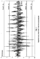
- the output signal of another acceleration sensor (not shown), which is shown in its time profile in FIG. 3 and is also used, for example, in the context of airbag electronics, occurs, for example, when braking hard on a roadway as Washboard ". This is to be understood to mean a course of the road surface in which road surface elevations are present at regular intervals.
- the acceleration values reach values of almost 6 g, values of about 3 g occurring particularly frequently.
- acceleration values which, for example, are above 3 g for the vehicle shown here, can permanently damage vehicle parts, for example on the chassis. This is taken into account by evaluating the accelerations in excess of 3 g and the sum of these evaluations. This is explained with reference to FIG. 4.
- the evaluation of the extreme accelerations is shown by way of example in FIG. 4.
- an evaluation takes place in the sense of a temporal integration.
- the integrals thus obtained are summed up.
- the energy input is calculated by taking into account the acceleration amplitudes and their duration, and the sum of these entries is calculated as Load index ".
- the integration and thus an increase in the load index takes place to an extent which corresponds to the energy input of the respective integral acceleration peak.
- the course of the load index L is also shown in FIG. 4.
- the scale from 0 up to 0.1 is only intended to illustrate and be exemplary.
- the threshold here 3 or 5 g, depends on the particular circumstances of the vehicle, the position of the acceleration sensor, its response behavior etc. and can be determined on the basis of driving tests.
- the output signals of other accelerometers can also be taken into account.
- the evaluation and summation of the output signals of the acceleration sensor (s) can also differ from the method shown and / or can differ from one another in the case of several acceleration sensors. In any case, in vehicles with one or more acceleration sensors, only a different evaluation of the output signals of the acceleration sensor gives the possibility of not only recognizing a crash and thus the need to trigger safety devices, but also the possibility, possibly and also not detect visible damage to the vehicle and its parts.
Landscapes
- Physics & Mathematics (AREA)
- General Physics & Mathematics (AREA)
- Air Bags (AREA)
- Electric Propulsion And Braking For Vehicles (AREA)
Applications Claiming Priority (4)
| Application Number | Priority Date | Filing Date | Title |
|---|---|---|---|
| DE1995145171 DE19545171A1 (de) | 1995-12-04 | 1995-12-04 | Verfahren zur Ermittlung von Fahrwerks-Überbeanspruchungen an Fahrzeugen |
| DE19545171 | 1995-12-04 | ||
| DE19602816 | 1996-01-26 | ||
| DE19602816A DE19602816A1 (de) | 1996-01-26 | 1996-01-26 | Verfahren zur Ermittlung von Fahrzeug-Überbeanspruchungen |
Publications (3)
| Publication Number | Publication Date |
|---|---|
| EP0778461A2 true EP0778461A2 (fr) | 1997-06-11 |
| EP0778461A3 EP0778461A3 (fr) | 1998-09-16 |
| EP0778461B1 EP0778461B1 (fr) | 2003-08-27 |
Family
ID=26020921
Family Applications (1)
| Application Number | Title | Priority Date | Filing Date |
|---|---|---|---|
| EP96117569A Expired - Lifetime EP0778461B1 (fr) | 1995-12-04 | 1996-11-02 | Procédé de détermination de surcharge pour véhicule |
Country Status (4)
| Country | Link |
|---|---|
| EP (1) | EP0778461B1 (fr) |
| JP (1) | JPH09178621A (fr) |
| DE (1) | DE59610687D1 (fr) |
| ES (1) | ES2204986T3 (fr) |
Cited By (2)
| Publication number | Priority date | Publication date | Assignee | Title |
|---|---|---|---|---|
| CN106918459A (zh) * | 2016-06-26 | 2017-07-04 | 黑龙江工程学院 | 货车超载判定方法 |
| CN116030547A (zh) * | 2022-11-25 | 2023-04-28 | 广东坤尚科技有限公司 | 装载货车整车质量检测过程的监管方法 |
Family Cites Families (6)
| Publication number | Priority date | Publication date | Assignee | Title |
|---|---|---|---|---|
| US4016766A (en) * | 1971-04-26 | 1977-04-12 | Systron Donner Corporation | Counting accelerometer apparatus |
| IT1184937B (it) * | 1985-03-29 | 1987-10-28 | Fiat Ferroviaria Savigliano | Metodo ed apparecchiatura per la segnalazione dell instabilita dinamica di rotabili ferrotramviari |
| FR2615624A1 (fr) * | 1987-05-19 | 1988-11-25 | Curti Jean | Dispositif de controle des conditions de deplacement d'un mobile, en particulier de roulage d'un vehicule automobile |
| JP3058942B2 (ja) * | 1991-06-27 | 2000-07-04 | 三菱電機株式会社 | ナビゲーション装置 |
| DE4223562A1 (de) * | 1992-07-17 | 1993-09-23 | Daimler Benz Ag | Verfahren zur einflussnahme auf die ausloesung eines insassenrueckhaltesystems in einem kraftfahrzeug und vorrichtung zur durchfuehrung des verfahrens |
| DE4226010A1 (de) * | 1992-08-06 | 1994-02-10 | Porsche Ag | Verfahren und Vorrichtung zum Überwachen der Lebensdauer von Fahrzeugbauteilen |
-
1996
- 1996-11-02 ES ES96117569T patent/ES2204986T3/es not_active Expired - Lifetime
- 1996-11-02 DE DE59610687T patent/DE59610687D1/de not_active Expired - Lifetime
- 1996-11-02 EP EP96117569A patent/EP0778461B1/fr not_active Expired - Lifetime
- 1996-12-03 JP JP8322970A patent/JPH09178621A/ja active Pending
Non-Patent Citations (1)
| Title |
|---|
| None |
Cited By (3)
| Publication number | Priority date | Publication date | Assignee | Title |
|---|---|---|---|---|
| CN106918459A (zh) * | 2016-06-26 | 2017-07-04 | 黑龙江工程学院 | 货车超载判定方法 |
| CN106918459B (zh) * | 2016-06-26 | 2020-02-07 | 哈尔滨明公科技有限公司 | 货车超载判定方法 |
| CN116030547A (zh) * | 2022-11-25 | 2023-04-28 | 广东坤尚科技有限公司 | 装载货车整车质量检测过程的监管方法 |
Also Published As
| Publication number | Publication date |
|---|---|
| EP0778461A3 (fr) | 1998-09-16 |
| JPH09178621A (ja) | 1997-07-11 |
| DE59610687D1 (de) | 2003-10-02 |
| EP0778461B1 (fr) | 2003-08-27 |
| ES2204986T3 (es) | 2004-05-01 |
Similar Documents
| Publication | Publication Date | Title |
|---|---|---|
| EP2136195B1 (fr) | Procédé et dispositif d'essai d'un amortisseur de chocs intégré dans un véhicule automobile | |
| DE69931535T2 (de) | Nutzlastüberwachungsvorrichtung für ein Zugfahrzeug mit Anhänger | |
| DE102017221891B4 (de) | Verfahren zum Bestimmen eines Schadens, der bei einem Unfall zwischen einem Fahrzeug und einem Stoßpartner an dem Fahrzeug auftritt | |
| DE4416991A1 (de) | Verfahren und Einrichtung zum Warnen der Fahrer von Lastkraftwagen vor Kippgefahr bei Kurvenfahrten | |
| DE102012218426B4 (de) | Verfahren, Steuergerät und System zum Ermitteln eines, einen Zustand zumindest einer Komponente eines Kraftfahrzeugs kennzeichnenden Parameters | |
| EP1298020B1 (fr) | Procédé pour déterminer la masse d'un véhicule automobile en tenant compte des differentes situations de counduit | |
| EP2861949B1 (fr) | Dispositif et procédé de contrôle de la pression de gonflage d'un pneu | |
| DE102018117680A1 (de) | Bestimmung des Gesundheitszustands des Dämpfers mittels indirekter Messungen | |
| DE4226010A1 (de) | Verfahren und Vorrichtung zum Überwachen der Lebensdauer von Fahrzeugbauteilen | |
| WO2013149824A1 (fr) | Procédé et dispositif pour contrôler la pression de gonflage | |
| DE102019105535A1 (de) | Automatisches Erfassen eines Fahrzeugschadens bei einem Unfall | |
| EP1273496B1 (fr) | Procédé de classification de chaussée | |
| EP0778461B1 (fr) | Procédé de détermination de surcharge pour véhicule | |
| DE102008027526B4 (de) | Verfahren zur prognostischen Bewertung eines voraussschauenden Sicherheitssystems eines Kraftfahrzeugs | |
| DE102012011977A1 (de) | Verfahren und Vorrichtung zum Bestimmen des Fahrverhaltens von Fahrzeugführern | |
| DE19545171A1 (de) | Verfahren zur Ermittlung von Fahrwerks-Überbeanspruchungen an Fahrzeugen | |
| DE102008017354A1 (de) | Aufpralldetektionssystem | |
| DE102019133870B4 (de) | Verfahren zum bestimmen der belastung eines lenksystems in einem fahrzeug | |
| EP2834610A1 (fr) | Procédé et dispositif pour contrôler la pression de gonflage | |
| EP2738538B1 (fr) | Procédé et véhicule automobile pour détecter des sollicitations qui s'exercent sur un véhicule automobile | |
| DE10243536B4 (de) | Verfahren und Vorrichtung zur Auslegung von Fahrzeugen und/oder Fahrzeugbauteilen | |
| DE102009051989B4 (de) | Stoßdämpfungsvorrichtung für ein Kraftfahrzeug | |
| DE102021131676A1 (de) | Flurförderzeug zum Befahren eines Untergrunds | |
| DE102022203543B3 (de) | Diagnose der Bremsanlage eines Anhängers anhand eines Beschleunigungssignals | |
| DE102004021550A1 (de) | Verfahren zur Ermittlung von Überbeanspruchungen eines Fahrzeugfahrwerks |
Legal Events
| Date | Code | Title | Description |
|---|---|---|---|
| PUAI | Public reference made under article 153(3) epc to a published international application that has entered the european phase |
Free format text: ORIGINAL CODE: 0009012 |
|
| AK | Designated contracting states |
Kind code of ref document: A2 Designated state(s): DE ES FR GB IT SE |
|
| PUAL | Search report despatched |
Free format text: ORIGINAL CODE: 0009013 |
|
| AK | Designated contracting states |
Kind code of ref document: A3 Designated state(s): DE ES FR GB IT SE |
|
| 17P | Request for examination filed |
Effective date: 19981006 |
|
| 17Q | First examination report despatched |
Effective date: 20010226 |
|
| GRAH | Despatch of communication of intention to grant a patent |
Free format text: ORIGINAL CODE: EPIDOS IGRA |
|
| GRAS | Grant fee paid |
Free format text: ORIGINAL CODE: EPIDOSNIGR3 |
|
| GRAA | (expected) grant |
Free format text: ORIGINAL CODE: 0009210 |
|
| AK | Designated contracting states |
Designated state(s): DE ES FR GB IT SE |
|
| REG | Reference to a national code |
Ref country code: GB Ref legal event code: FG4D Free format text: NOT ENGLISH |
|
| GBT | Gb: translation of ep patent filed (gb section 77(6)(a)/1977) | ||
| REF | Corresponds to: |
Ref document number: 59610687 Country of ref document: DE Date of ref document: 20031002 Kind code of ref document: P |
|
| REG | Reference to a national code |
Ref country code: SE Ref legal event code: TRGR |
|
| REG | Reference to a national code |
Ref country code: ES Ref legal event code: FG2A Ref document number: 2204986 Country of ref document: ES Kind code of ref document: T3 |
|
| ET | Fr: translation filed | ||
| PLBE | No opposition filed within time limit |
Free format text: ORIGINAL CODE: 0009261 |
|
| STAA | Information on the status of an ep patent application or granted ep patent |
Free format text: STATUS: NO OPPOSITION FILED WITHIN TIME LIMIT |
|
| 26N | No opposition filed |
Effective date: 20040528 |
|
| PGFP | Annual fee paid to national office [announced via postgrant information from national office to epo] |
Ref country code: ES Payment date: 20051028 Year of fee payment: 10 |
|
| PGFP | Annual fee paid to national office [announced via postgrant information from national office to epo] |
Ref country code: SE Payment date: 20051107 Year of fee payment: 10 |
|
| PGFP | Annual fee paid to national office [announced via postgrant information from national office to epo] |
Ref country code: GB Payment date: 20051124 Year of fee payment: 10 |
|
| PGFP | Annual fee paid to national office [announced via postgrant information from national office to epo] |
Ref country code: FR Payment date: 20051128 Year of fee payment: 10 |
|
| PG25 | Lapsed in a contracting state [announced via postgrant information from national office to epo] |
Ref country code: SE Free format text: LAPSE BECAUSE OF NON-PAYMENT OF DUE FEES Effective date: 20061103 |
|
| PGFP | Annual fee paid to national office [announced via postgrant information from national office to epo] |
Ref country code: IT Payment date: 20061130 Year of fee payment: 11 |
|
| EUG | Se: european patent has lapsed | ||
| GBPC | Gb: european patent ceased through non-payment of renewal fee |
Effective date: 20061102 |
|
| REG | Reference to a national code |
Ref country code: FR Ref legal event code: ST Effective date: 20070731 |
|
| PG25 | Lapsed in a contracting state [announced via postgrant information from national office to epo] |
Ref country code: GB Free format text: LAPSE BECAUSE OF NON-PAYMENT OF DUE FEES Effective date: 20061102 |
|
| REG | Reference to a national code |
Ref country code: ES Ref legal event code: FD2A Effective date: 20061103 |
|
| PG25 | Lapsed in a contracting state [announced via postgrant information from national office to epo] |
Ref country code: FR Free format text: LAPSE BECAUSE OF NON-PAYMENT OF DUE FEES Effective date: 20061130 Ref country code: ES Free format text: LAPSE BECAUSE OF NON-PAYMENT OF DUE FEES Effective date: 20061103 |
|
| PG25 | Lapsed in a contracting state [announced via postgrant information from national office to epo] |
Ref country code: IT Free format text: LAPSE BECAUSE OF NON-PAYMENT OF DUE FEES Effective date: 20071102 |
|
| PGFP | Annual fee paid to national office [announced via postgrant information from national office to epo] |
Ref country code: DE Payment date: 20131115 Year of fee payment: 18 |
|
| REG | Reference to a national code |
Ref country code: DE Ref legal event code: R119 Ref document number: 59610687 Country of ref document: DE |
|
| PG25 | Lapsed in a contracting state [announced via postgrant information from national office to epo] |
Ref country code: DE Free format text: LAPSE BECAUSE OF NON-PAYMENT OF DUE FEES Effective date: 20150602 |