EP0778465A1 - Détecteur de bulles - Google Patents
Détecteur de bulles Download PDFInfo
- Publication number
- EP0778465A1 EP0778465A1 EP96203409A EP96203409A EP0778465A1 EP 0778465 A1 EP0778465 A1 EP 0778465A1 EP 96203409 A EP96203409 A EP 96203409A EP 96203409 A EP96203409 A EP 96203409A EP 0778465 A1 EP0778465 A1 EP 0778465A1
- Authority
- EP
- European Patent Office
- Prior art keywords
- transducer
- ultrasonic
- bubbles
- conduit
- liquid
- Prior art date
- Legal status (The legal status is an assumption and is not a legal conclusion. Google has not performed a legal analysis and makes no representation as to the accuracy of the status listed.)
- Withdrawn
Links
- 239000007788 liquid Substances 0.000 claims abstract description 24
- 239000000839 emulsion Substances 0.000 claims abstract description 21
- 238000006073 displacement reaction Methods 0.000 claims abstract description 3
- 238000002604 ultrasonography Methods 0.000 claims description 14
- 239000012530 fluid Substances 0.000 claims description 9
- 238000000034 method Methods 0.000 claims description 6
- 239000000463 material Substances 0.000 abstract description 7
- 238000004519 manufacturing process Methods 0.000 abstract description 6
- 230000007547 defect Effects 0.000 abstract description 3
- 230000000246 remedial effect Effects 0.000 abstract description 3
- 238000001514 detection method Methods 0.000 description 14
- 239000007787 solid Substances 0.000 description 13
- 229920001971 elastomer Polymers 0.000 description 12
- 239000011248 coating agent Substances 0.000 description 9
- 238000000576 coating method Methods 0.000 description 9
- 239000013078 crystal Substances 0.000 description 9
- 230000035945 sensitivity Effects 0.000 description 8
- 239000002245 particle Substances 0.000 description 7
- 229910052751 metal Inorganic materials 0.000 description 6
- 239000002184 metal Substances 0.000 description 6
- 239000003990 capacitor Substances 0.000 description 3
- 230000001419 dependent effect Effects 0.000 description 3
- 238000012360 testing method Methods 0.000 description 3
- 238000011144 upstream manufacturing Methods 0.000 description 3
- 235000009508 confectionery Nutrition 0.000 description 2
- 238000010276 construction Methods 0.000 description 2
- 230000002950 deficient Effects 0.000 description 2
- 230000000694 effects Effects 0.000 description 2
- 235000013305 food Nutrition 0.000 description 2
- 239000004972 Polyurethane varnish Substances 0.000 description 1
- BQCADISMDOOEFD-UHFFFAOYSA-N Silver Chemical compound [Ag] BQCADISMDOOEFD-UHFFFAOYSA-N 0.000 description 1
- 230000032683 aging Effects 0.000 description 1
- 239000004411 aluminium Substances 0.000 description 1
- 229910052782 aluminium Inorganic materials 0.000 description 1
- XAGFODPZIPBFFR-UHFFFAOYSA-N aluminium Chemical compound [Al] XAGFODPZIPBFFR-UHFFFAOYSA-N 0.000 description 1
- 230000003321 amplification Effects 0.000 description 1
- 230000000712 assembly Effects 0.000 description 1
- 238000000429 assembly Methods 0.000 description 1
- 239000008280 blood Substances 0.000 description 1
- 210000004369 blood Anatomy 0.000 description 1
- 230000008878 coupling Effects 0.000 description 1
- 238000010168 coupling process Methods 0.000 description 1
- 238000005859 coupling reaction Methods 0.000 description 1
- 238000010586 diagram Methods 0.000 description 1
- 238000009826 distribution Methods 0.000 description 1
- 238000007689 inspection Methods 0.000 description 1
- 238000002955 isolation Methods 0.000 description 1
- 238000003199 nucleic acid amplification method Methods 0.000 description 1
- 238000003825 pressing Methods 0.000 description 1
- 230000002035 prolonged effect Effects 0.000 description 1
- 238000010926 purge Methods 0.000 description 1
- 238000005070 sampling Methods 0.000 description 1
- 238000007789 sealing Methods 0.000 description 1
- 230000035939 shock Effects 0.000 description 1
- 229910052709 silver Inorganic materials 0.000 description 1
- 239000004332 silver Substances 0.000 description 1
Images


Classifications
-
- G—PHYSICS
- G01—MEASURING; TESTING
- G01N—INVESTIGATING OR ANALYSING MATERIALS BY DETERMINING THEIR CHEMICAL OR PHYSICAL PROPERTIES
- G01N29/00—Investigating or analysing materials by the use of ultrasonic, sonic or infrasonic waves; Visualisation of the interior of objects by transmitting ultrasonic or sonic waves through the object
- G01N29/02—Analysing fluids
- G01N29/032—Analysing fluids by measuring attenuation of acoustic waves
-
- A—HUMAN NECESSITIES
- A61—MEDICAL OR VETERINARY SCIENCE; HYGIENE
- A61M—DEVICES FOR INTRODUCING MEDIA INTO, OR ONTO, THE BODY; DEVICES FOR TRANSDUCING BODY MEDIA OR FOR TAKING MEDIA FROM THE BODY; DEVICES FOR PRODUCING OR ENDING SLEEP OR STUPOR
- A61M1/00—Suction or pumping devices for medical purposes; Devices for carrying-off, for treatment of, or for carrying-over, body-liquids; Drainage systems
- A61M1/36—Other treatment of blood in a by-pass of the natural circulatory system, e.g. temperature adaptation, irradiation ; Extra-corporeal blood circuits
- A61M1/3621—Extra-corporeal blood circuits
- A61M1/3626—Gas bubble detectors
-
- G—PHYSICS
- G01—MEASURING; TESTING
- G01N—INVESTIGATING OR ANALYSING MATERIALS BY DETERMINING THEIR CHEMICAL OR PHYSICAL PROPERTIES
- G01N2291/00—Indexing codes associated with group G01N29/00
- G01N2291/02—Indexing codes associated with the analysed material
- G01N2291/024—Mixtures
- G01N2291/02433—Gases in liquids, e.g. bubbles, foams
-
- G—PHYSICS
- G01—MEASURING; TESTING
- G01N—INVESTIGATING OR ANALYSING MATERIALS BY DETERMINING THEIR CHEMICAL OR PHYSICAL PROPERTIES
- G01N2291/00—Indexing codes associated with group G01N29/00
- G01N2291/04—Wave modes and trajectories
- G01N2291/042—Wave modes
- G01N2291/0422—Shear waves, transverse waves, horizontally polarised waves
-
- G—PHYSICS
- G01—MEASURING; TESTING
- G01N—INVESTIGATING OR ANALYSING MATERIALS BY DETERMINING THEIR CHEMICAL OR PHYSICAL PROPERTIES
- G01N2291/00—Indexing codes associated with group G01N29/00
- G01N2291/10—Number of transducers
- G01N2291/102—Number of transducers one emitter, one receiver
Definitions
- the present invention relates to apparatus for detecting bubbles in a liquid flowing through a conduit and more particularly to such apparatus in which bubble detection is carried out sonically or ultrasonically.
- the invention is particularly, but not exclusively, applicable to the detection of bubbles in liquid photographic emulsion flowing to coating apparatus for coating film and paper for photography.
- bubble detector for this purpose have been proposed, including detectors using ultrasound.
- ultrasonic detectors using the method of attenuation of ultrasound have been utilised in photographic emulsion delivery systems.
- no bubbles at all should be present in the emulsion coated onto film, paper, etc. and certainly no bubbles must be present of a size to produce a detectable defect in the finished product.
- the appearance of bubbles in the coating stage and immediately preceding that stage generally indicates that some part of the system upstream of that stage has become defective, for example that a valve or seal has become faulty, allowing air to pass into the system.
- bubble detectors for photographic emulsion delivery systems do not afford reliable detection of bubbles.
- the detectors used hitherto, utilising ultrasound attention methods are on the one hand also sensitive to solids and turbulence in the liquid and on the other hand also have "dead" spots in the sampling volume and so may fail to detect bubbles.
- a sonic or ultrasonic bubble detector comprising a sonic or ultrasonic transducer placed in sound or ultrasound transmitting relationship with a conduit for fluid flow, means for supplying an a.c. electrical signal to said transducer to cause the transducer to generate and to direct across or through said conduit corresponding sonic or ultrasonic energy, and means for sensing the impedance of said transducer to said electrical signal and for detecting from variations in said impedance the presence of bubbles in the liquid flowing through said conduit.
- a bubble detector comprising a conduit for liquid to be monitored, said conduit having opposing flattened, generally parallel walls, and a transducer engaged with one of said walls and operable to apply alternating displacements to said one of said walls, in a direction generally normal to said walls to transmit sonic or ultrasonic waves through liquid passing through said conduit.
- a bubble detector comprising means for generating a sonic or ultrasonic signal with a frequency of 100kHz or lower.
- the lower frequency limit for the ultrasonic signal used is determined by the consideration that the frequency used may not be lower than the resonant frequency of the smallest bubble to be detected which has been found to be approximately 50kHz for a bubble 60 ⁇ m in diameter.
- the invention may find application in fields other than photographic coating.
- the bubble detector of the present invention may be of utility in blood transfusion and like equipment.
- bubbles or at any rate bubbles of non-sterile air, are undesirable in food products or confectionery, so that the bubble detector of the present invention may also be useful in food processing systems or confectionery manufacturing equipment.
- the sizes of the bubbles which are of interest and/or the sizes of the solid particles which may be present in the medium detected may render advantageous a frequency lower or higher than the 50kHz frequency which the applicants have found ideal for bubble detection in photographic emulsion.
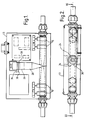
- the apparatus includes a sensor pipe 10 in the form of a length of metal tubing of circular section over most of its length but flattened over a middle section to afford two parallel flat wall portions.
- the extent to which the metal tube is thus flattened is selected to afford such flat wall portion of adequate width without substantially reducing the flow cross-section of the tube in the region between said flat wall portions and thus without substantially altering flow conditions through the pipe.
- An ultrasonic transducer head 16 is secured to one of the flat walls in the central section of pipe 10 and projects substantially perpendicularly from the pipe 10 relative to the longitudinal axis of the pipe. Ultrasound-absorbing lengths 18 of rubber tubing are fitted tightly over the pipe 10 and extend to the transducer head.
- the sensor pipe 10 has a diameter of 15 mm adjacent its ends and is flattened in its middle region to afford a gap of around 6 mm between the flat wall portions.
- the ultrasonic head has an operating frequency around 50kHz.
- the pipe 10 is dimensioned so as to be tuned to the same frequency.
- the free ends of the pipe 10 stop short of the free ends of pipe stubs 11 which pass through and are secured to respective opposite end walls of a housing 13 of the apparatus, the pipe stubs 11 being co-axial with the sensor pipe 10.
- Each length 18 of rubber tubing extends past the respective end of the sensor pipe and over the adjacent end of the adjacent pipe stub 11 and thus also provides a connection for fluid flow between the pipe 10 and the respective stub 11.
- Clips 15 on each length 18 of rubber tubing clamp the tubing to the respective pipe stub 11 and to the adjoining end of the sensor pipe.
- the apparatus is connected in a pipeline for conveying the liquid to be monitored, namely liquid photographic emulsion in the example described, respective parts of the pipeline upstream and downstream of the apparatus being connected to respective ones of the stubs 11.
- reinforced rubber piping may be used for lengths 18 and clips 15 dispensed with.
- the rubber tubing serves to provide a fluid tight connection between the stubs 11 and pipe 10 and at the same time serves to dampen the vibrations of the pipe 10 and to isolate the pipe 10 from stubs 11 as regards ultrasonic vibration.
- the rubber tubing also isolates the pipe 10 and transducer from mechanical vibrations transmitted to the apparatus via the pipeline in which it is connected.
- the rubber tubing also serves the significant purpose, as explained below, of lowering the working Q of the system.
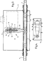
- the transducer head consists of a "Langevin sandwich” type transducer bolted to an ultrasound-conducting and directing element 20 referred to herein for convenience as a "horn” and which comprises a tapering metal bar or rod secured at its narrower end to pipe 10.
- the transducer head is resonant at a frequency of 50kHz.
- the horn 20 and sensor pipe 10 are designed and adjusted to be resonant at the same frequency of 50kHz.
- the transducer head is relatively insensitive to mechanical vibration but is preferably mounted on rubber couplings for isolation from externally originating vibrations.
- the horn 20 has a screw-threaded bore extending longitudinally from the end face at its broader end, which bore receives a screw-threaded bolt 24.
- the bolt 24 passes through a stack of annular components comprising, in order from the horn, an aluminium gasket 17, a first annular metal end mass 26, a first annular piezo electric crystal 28, a first annular washer and contact plate 30 mounted so as to be insulated from the bolt and having a radially extending contact tag, a second annular piezo-electric crystal 32, a second annular washer and contact plate 34 having a radially extending contact tag, and a second annular metal end mass 36.
- the end masses 26 and 36 are of equal diameter whilst the crystals 28 and 32 are of a diameter slightly smaller than the end masses 26 and 36.
- the diameter of the horn at its wider end adjoining the transducer is equal to that of each of said annular components.
- the crystals 28 and 30 are matched, in manner known per se, as are the end masses 26 and 36.
- the bolt 24 effectively forms part of the tuned element constituted by the horn 20 and is taken into account in designing and adjusting the resonant frequency of the horn.
- the second annular end mass 36 has a smooth internal bore receiving the bolt 24, whereas the first annular end mass 36 has an internally screwthreaded bore which screwthreadedly engages the screw-threaded part of the bolt shank.
- the end mass 26 thus also acts as a nut screwed onto the bolt and the crystals 28 and 32, washers 30 and 34 and end mass 36 are clamped tightly between the bolt head and the end mass 26.
- the bolt 24, thus carrying the transducer comprises crystals 28 and 32 and the end masses 26 and 36 is, in assembly, screwed into the horn 20 until the end mass 26 abuts the end face of the horn, but need not be screwed very tightly against the horn, the torque required to screw the transducer into the horn being substantially smaller than that required to screw the end mass 26 onto the bolt to clamp the end mass 36 and crystals 28 and 32.
- This feature makes it possible, when necessary, to unscrew the transducer from the horn, for replacement, and to screw the replacement onto the horn, without special tools and without the risk of damage to the sensor pipe or the connection of the horn with the sensor pipe.
- the dimensions of the crystals used should be such as to give a first "crystal only" resonance at least 50% higher than the desired final working frequency of the transducer.
- the transducer is driven by a 50kHz a.c. signal applied between contact plates 30 and 34 by driving circuitry described below.
- the length of said assembly of annular elements, forming the Langevin sandwich is preferably at least 50% longer than its diameter.
- the final assembly is coated with polyurethane varnish to keep out moisture.
- the tip of the horn is silver soldered onto one flat wall of the sensor pipe 10, which acts rather like a matched load on the transducer.
- the horn and the sensor pipe 10 are separately tuned to the resonant frequency of the transducer.
- the rubber tubing 18 is selected so as to reduce the working electrical Q of the transducer head to about 25.
- the driving circuitry driving the transducer can be very simple, as minor frequency drift is then of no great importance. Sensitivity of the head is lost of course by lowering the Q in this way, but the transducer is so efficient in the first place that when used at a Q of 25 it still provides a very good S/N ratio for detection of small bubbles.
- the lowering of the Q in this way renders negligible in effect the fairly substantial variations in Q which may occur, between different nominally identical transducer/horn/sensor pipe assemblies, thereby making practicable volume production of the bubble detector without provision for or need for involved tuning procedures on set-up or in use of the apparatus.
- the maximum cross-sectional dimension of the pipe 10 is substantially less than one wavelength, in the liquid emulsion, of the 50kHz ultrasound used. Consequently transverse standing waves are not set up and there are no "dead" zones through which an otherwise detectable bubble can pass to avoid detection.
- the flattening of the sensor pipe 10 in the region to which the horn 20 is secured besides facilitating the mounting of the horn, causes the wall of the pipe to which the horn 20 is attached to act rather like a diaphragm, ensuring that a significant proportion of the ultrasonic energy transmitted by the horn 20 is transmitted through the liquid within the pipe rather than, for example, being largely confined to the metal of the sensor pipe.
- the extent of such flattening is kept below that which would substantially reduce the flow cross-section of the pipe and accordingly, fluid flow through the sensor pipe is hardly impeded by the flattening.
- the electrical impedance of the transducer is dependent, inter alia, upon the mechanical impedance of the system including the fluid filled sensor pipe 10 which in turn varies according to whether or not bubbles are present in such fluid in the region of the tip of the horn 20 and upon the size and/or number of such bubbles, if present.
- the detector circuitry associated with the transducer serves to detect changes in the electrical impedance of the transducer and to provide signals representative of such changes to a chart recorder or other display device.
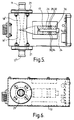
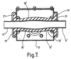
- the sleeves 18' are extended, over the respective ends of the sensor pipe, through apertures in opposing side walls of the housing, from the outside and are clamped between the respective said side wall and a respective annular washer 21.
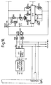
- the construction of the transducer assembly is shown more clearly in Figure 5 than in Figure 3.
- the transducer 16 is electrically connected in a bridge circuit 60 as one arm thereof, the other arms being formed by resistors R 2 and R 3 and a variable resistor VR5 (adjusted to balance the bridge).
- a capacitor C1 connected in parallel with resistor VR5 serves to balance out the capacitive part of the transducer, the ultrasonic a.c. signal from generator (shown in Figure 10) being connected across the bridge between points 62 and 64 thereof (point 64 being earthed) whilst the inputs of respective line driver amplifiers IC1 and IC2 are connected to points 66 and 68 of the bridge circuit.
- the bridge circuitry and line driver amplifiers IC1 and IC2 are mounted in the housing 13 in close proximity to the transducer to minimise interference.
- the amplifiers IC1 and IC2 each have one common input/output terminal earthed, the point 64 and the earthed terminals of amplifiers IC1 and IC2 being connected to a common earth point within casing 13.
- Amplifiers IC1 and IC2 provide their outputs on respective coaxial cables which extend to remotely located further amplifying and processing circuitry shown in Figure 9.
- This further circuitry comprises a balanced amplifier and detector comprising two amplifier and detector channels including respectively, on the one hand operational amplifiers IC3 and IC5, and on the other hand operational amplifiers IC4 and IC6, these two channels again being balanced with respect to earth, each said channel receiving its input from a respective one of amplifiers IC1 and IC2.
- These channels each include an amplifier stage, incorporating the op-amp IC3 and IC4 respectively, and a detector stage, incorporating the op- amp IC5 or IC6 respectively, diodes D3, D4, D5, D6 respectively and capacitors C13 and C21 respectively.
- the amplifiers incorporating op-amps IC3 and IC4 and having a gain of 2.5, are also active filters with a Q of 9. They provide rejection of unwanted harmonics of the 50kHz working frequency which might carry some sensitivity to solids in the detector head.
- the 50kHz signals from the amplifier IC1 and IC2 after amplification by the amplifier stages incorporating IC3 and IC4, are fed to the respective detector stages including diodes D3, D4 and D5, D6, which stages provide respective D.C. signals to a differential amplifier IC7 with a gain of 30.
- the provision of the detector stages in advance of the differential amplifier renders the circuit insensitive to any phase differences between the 50kHz signals from line amplifiers IC1 and IC2.
- the output from amplifier IC7 produced by a single bubble passing through the sensor pipe takes the form of an excursion from and return to the base line representing the normal "no-bubble" signal over a period which depends upon the flow rate and corresponds to the time that the bubble is within sensing range of the transducer head, the amplitude of such excursion being dependent on bubble size.
- a meter permanently connected to IC7 output gives a useful indication of state of balance of the input circuits.
- the signals from differential amplifier IC7 are A.C.
- a full wave rectifier including op-amps IC8a and IC8b, the full wave rectifier in conjunction with capacitor C24 forming a peak detector, the output of which is passed to the output driver stage incorporating amplifiers IC10 and IC11.
- the purpose of the peak detector is to make the chart recorder display independent of flow rate.
- C24 and R41 give the decay time constant of the peak detector.
- the transducer acts simultaneously as a radiator of ultrasound and as a receiver.
- a finite medium such as the liquid contained in the sensor pipe 10
- the mechanical impedance presented to the transducer by that liquid varies slightly according to whether or not bubbles are present, and this variation in mechanical impedance results in a corresponding variation in electrical impedance of the transducer, which is sensed by the balanced bridge circuit and forms the basis for bubble detection.
- the voltage developed across the transducer varies in accordance with the amplitude of movement of the transducer end face and hence with the compressibility of the fluid in the sensing region of the sensor pipe 10.
- the bridge is balanced for bubble-free liquid so that the presence of bubbles in the sensing region of the sensor pipe 10 produces an out-of-balance bridge voltage dependent on the size and/or number of bubbles.
- a relatively low ultrasonic frequency is used such that the corresponding wavelength in the fluid is considerably greater than any dimension relating to the cross sectional area of the sensor pipe.
- the frequency must be no lower than the resonant frequency of the minimum size of bubble to be detected.
- a frequency of at least 50kHz must be used. Sensitivity to solids increases with increasing frequency.
- Tests show complete insensitivity to solids at 18kHz. Tests also show that sensitivity to individual bubbles is substantially proportional to bubble size.
- the bridge circuit in addition to affording sensitivity, serves to balance out noise and provide a balanced electrical signal so that a balanced feeder can be used to the main part of the circuit several metres away from the transducer head.
- Sensitivity in the preferred embodiments has been found to be independent of flow rate for small numbers of bubbles.
- the wavelength of the ultrasound used should be greater than, or at least not substantially less than the cross-sectional dimensions of the sensor pipe.
- a sensor pipe may be used which has a diameter many times greater than a wavelength of the ultrasound used.
- ultrasound is used, preferably having a frequency in the region of 50kHz
- the minimum size of bubble which may be of interest may be so large that frequencies within the audible range may be preferred, for example frequencies down to 10kHz or even lower, and it should be appreciated that the use of audible sound is not excluded from the scope of the invention.
Landscapes
- Physics & Mathematics (AREA)
- Acoustics & Sound (AREA)
- Health & Medical Sciences (AREA)
- Life Sciences & Earth Sciences (AREA)
- Chemical & Material Sciences (AREA)
- Analytical Chemistry (AREA)
- Biochemistry (AREA)
- General Health & Medical Sciences (AREA)
- General Physics & Mathematics (AREA)
- Immunology (AREA)
- Pathology (AREA)
- Investigating Or Analyzing Materials By The Use Of Ultrasonic Waves (AREA)
Applications Claiming Priority (2)
| Application Number | Priority Date | Filing Date | Title |
|---|---|---|---|
| GBGB9524949.6A GB9524949D0 (en) | 1995-12-06 | 1995-12-06 | Bubble detector |
| GB9524949 | 1995-12-06 |
Publications (1)
| Publication Number | Publication Date |
|---|---|
| EP0778465A1 true EP0778465A1 (fr) | 1997-06-11 |
Family
ID=10785003
Family Applications (1)
| Application Number | Title | Priority Date | Filing Date |
|---|---|---|---|
| EP96203409A Withdrawn EP0778465A1 (fr) | 1995-12-06 | 1996-12-02 | Détecteur de bulles |
Country Status (4)
| Country | Link |
|---|---|
| US (1) | US5723773A (fr) |
| EP (1) | EP0778465A1 (fr) |
| JP (1) | JPH09178712A (fr) |
| GB (1) | GB9524949D0 (fr) |
Cited By (6)
| Publication number | Priority date | Publication date | Assignee | Title |
|---|---|---|---|---|
| WO2007080618A3 (fr) * | 2006-01-11 | 2007-09-20 | M P I S P A Sa | Procédé et instrument pour détecter l’air et/ou d’autres gaz à l’intérieur de liquides en transit |
| WO2010091314A3 (fr) * | 2009-02-06 | 2010-09-30 | Zevex, Inc. | Détecteur de bulles d'air |
| EP2372330A1 (fr) * | 2010-03-31 | 2011-10-05 | LIFEBRIDGE Medizintechnik AG | Détecteur de bulles |
| WO2013087247A1 (fr) * | 2011-12-13 | 2013-06-20 | Robert Bosch Gmbh | Dispositif de séparation de particules d'un courant gazeux ou liquide |
| CN104287776A (zh) * | 2014-10-13 | 2015-01-21 | 西安交通大学 | 非自由场内流动微泡的二维操控及其超声成像监控方法 |
| CN108627573A (zh) * | 2018-06-22 | 2018-10-09 | 韩继辉 | 一种利用声波检测金属注塑件内部气泡的设备 |
Families Citing this family (41)
| Publication number | Priority date | Publication date | Assignee | Title |
|---|---|---|---|---|
| US6196059B1 (en) * | 1997-08-11 | 2001-03-06 | Fraunhofer Gesellschaft Zur Forderung Der Angewandten Forschung E.V. | Piezoelectric resonator, process for the fabrication thereof including its use as a sensor element for the determination of the concentration of a substance contained in a liquid and/or for the determination of the physical properties of the liquid |
| US6758090B2 (en) * | 1998-06-15 | 2004-07-06 | Schlumberger Technology Corporation | Method and apparatus for the detection of bubble point pressure |
| US6408679B1 (en) * | 2000-02-04 | 2002-06-25 | The United States Of America As Represented By The Administrator Of The National Aeronautics And Space Administration | Bubble measuring instrument and method |
| US6711954B2 (en) | 2001-01-19 | 2004-03-30 | Lockheed Martin Corporation | Method and apparatus for improving the dynamic range of laser detected ultrasound in attenuative materials |
| RU2232384C2 (ru) * | 2001-01-23 | 2004-07-10 | Яхно Татьяна Анатольевна | Способ исследования многокомпонентной жидкости |
| US6622542B2 (en) * | 2001-03-20 | 2003-09-23 | Therox, Inc. | Bubble detector and method of use thereof |
| WO2003020405A1 (fr) * | 2001-08-28 | 2003-03-13 | Mitsubishi Rayon Co.,Ltd. | Dispositif et procede pour la fabrication d'une source gazeifiee et d'eau gazeuse, procede de commande de la densite de gaz appliquee a cette eau et module a membrane |
| US6786096B2 (en) | 2001-11-28 | 2004-09-07 | Battelle Memorial Institute | System and technique for detecting the presence of foreign material |
| US6992771B2 (en) * | 2001-11-28 | 2006-01-31 | Battelle Memorial Institute | Systems and techniques for detecting the presence of foreign material |
| DE602005027537D1 (de) * | 2004-01-14 | 2011-06-01 | Mitsubishi Rayon Co | System zur herstellung einer kohlensäurequelle |
| DE102006012993A1 (de) * | 2006-03-22 | 2007-09-27 | Mib Gmbh Messtechnik Und Industrieberatung | Leerrohrerkennung |
| US7805978B2 (en) | 2006-10-24 | 2010-10-05 | Zevex, Inc. | Method for making and using an air bubble detector |
| US7661293B2 (en) * | 2007-02-06 | 2010-02-16 | Cosense, Inc. | Ultrasonic system for detecting and quantifying of air bubbles/particles in a flowing liquid |
| WO2009029533A1 (fr) * | 2007-08-24 | 2009-03-05 | Zevex, Inc. | Détecteur ultrasonore d'air et de fluide |
| US8033157B2 (en) | 2007-10-01 | 2011-10-11 | Baxter International Inc. | Medical fluid air bubble detection apparatus and method |
| EP2268417A1 (fr) * | 2008-03-26 | 2011-01-05 | 3M Innovative Properties Company | Procédés de revêtement par glissement de deux ou plusieurs fluides |
| BRPI0910877A2 (pt) * | 2008-03-26 | 2015-10-06 | 3M Innovative Proferties Company | método para aplicar dois ou mais fluidos como um revestimento de deslizamento |
| US20110027493A1 (en) * | 2008-03-26 | 2011-02-03 | Yapel Robert A | Methods of slide coating fluids containing multi unit polymeric precursors |
| US7737534B2 (en) * | 2008-06-10 | 2010-06-15 | Northrop Grumman Systems Corporation | Semiconductor devices that include germanium nanofilm layer disposed within openings of silicon dioxide layer |
| US7673591B2 (en) * | 2008-06-10 | 2010-03-09 | Deere & Company | Nucleate boiling cooling system and method |
| US8327812B2 (en) * | 2009-07-24 | 2012-12-11 | Deere & Company | Nucleate boiling cooling system |
| US8353870B2 (en) | 2011-04-26 | 2013-01-15 | Fresenius Medical Care Holdings, Inc. | Medical temperature sensors and related systems and methods |
| US8836519B2 (en) | 2011-05-12 | 2014-09-16 | Fresenius Medical Care Holdings, Inc. | Determining the absence or presence of fluid in a dialysis system |
| US9333286B2 (en) | 2011-05-12 | 2016-05-10 | Fresenius Medical Care Holdings, Inc. | Medical tubing installation detection |
| WO2014070781A2 (fr) * | 2012-10-29 | 2014-05-08 | Hospira, Inc. | Passage d'écoulement de fluide pour améliorer une détection d'air en ligne |
| JP6107054B2 (ja) * | 2012-10-30 | 2017-04-05 | セイコーエプソン株式会社 | 液体輸送装置 |
| US9797851B2 (en) * | 2012-11-27 | 2017-10-24 | The University Of Akron | Integrated ultrasonic-inductive pulse sensor for wear debris detection |
| US20150133861A1 (en) | 2013-11-11 | 2015-05-14 | Kevin P. McLennan | Thermal management system and method for medical devices |
| US10143795B2 (en) | 2014-08-18 | 2018-12-04 | Icu Medical, Inc. | Intravenous pole integrated power, control, and communication system and method for an infusion pump |
| CN109222688B (zh) * | 2015-02-13 | 2022-02-08 | 金弘培 | 食品加工烹饪设备 |
| WO2016189419A1 (fr) | 2015-05-26 | 2016-12-01 | Hospira, Nc. | Dispositif jetable d'administration de fluide de perfusion destiné à une administration programmable de grands volumes de médicaments |
| JP6360529B2 (ja) * | 2016-08-31 | 2018-07-18 | 紀州技研工業株式会社 | 気泡検出センサ |
| JP6806329B2 (ja) * | 2016-12-01 | 2021-01-06 | 国立研究開発法人産業技術総合研究所 | 検査装置および検査方法 |
| US11517734B2 (en) * | 2017-06-21 | 2022-12-06 | Kristin Rossodivito | System and method for detecting air embolisms in lines for hemodynamic monitoring |
| US11573257B2 (en) * | 2019-06-20 | 2023-02-07 | The Boeing Company | Systems and methods for acoustically detecting dielectric breakdown and partial discharge events in electrical devices |
| USD939079S1 (en) | 2019-08-22 | 2021-12-21 | Icu Medical, Inc. | Infusion pump |
| KR102697268B1 (ko) * | 2020-12-21 | 2024-08-22 | 한국수력원자력 주식회사 | 포스트텐션 덕트 내 그리스의 공극 탐지 초음파 센서 시스템 |
| EP4049697B1 (fr) * | 2021-02-04 | 2025-12-17 | Micrel Medical Devices S.A. | Segment de tube de pompe à perfusion péristaltique et dispositif de pompe à perfusion doté d'un tel segment de tube |
| US12117420B2 (en) | 2021-03-30 | 2024-10-15 | International Business Machines Corporation | Sonar scanning water cooled coaxial cables |
| USD1052728S1 (en) | 2021-11-12 | 2024-11-26 | Icu Medical, Inc. | Medical fluid infusion pump |
| CN114152593A (zh) * | 2021-12-03 | 2022-03-08 | 浙江大学 | 一种具备气泡含量分析的浊度仪 |
Citations (6)
| Publication number | Priority date | Publication date | Assignee | Title |
|---|---|---|---|---|
| EP0053453A1 (fr) * | 1980-12-03 | 1982-06-09 | Baxter Travenol Laboratories, Inc. | Détecteur ultrasonore de bulles |
| JPS6491035A (en) * | 1987-10-01 | 1989-04-10 | Cho Onpa Kogyo Co | Detecting circuit of sensor for ultrasonic viscometer |
| WO1991016087A1 (fr) * | 1990-04-26 | 1991-10-31 | Infurex Ag | Procede et dispositif de detection de bulles de gaz dans des conduits remplis de liquide, notamment des conduits ou conteneurs tubulaires flexibles |
| EP0524605A1 (fr) * | 1991-07-22 | 1993-01-27 | Ivac Corporation | Détecteur de bulles d'air |
| EP0643301A1 (fr) * | 1993-09-10 | 1995-03-15 | Cobe Laboratories, Inc. | Procédé et dispositif de détection ultrasonore de bulles d'air |
| WO1996021151A1 (fr) * | 1995-01-05 | 1996-07-11 | Debiotech S.A. | Dispositif de controle de l'ecoulement d'un liquide dans une conduite tubulaire et notamment dans une pompe peristaltique |
Family Cites Families (12)
| Publication number | Priority date | Publication date | Assignee | Title |
|---|---|---|---|---|
| US3774717A (en) * | 1971-12-27 | 1973-11-27 | Univ Leland Stanford Junior | Method of and apparatus for particle detection and identification |
| GB1418181A (en) * | 1973-02-27 | 1975-12-17 | Cole E M | Ultrasonic detection of inclusions in a fluid flowing within a tube |
| US3974681A (en) * | 1973-10-23 | 1976-08-17 | Jerry Namery | Ultrasonic bubble detector |
| US4278932A (en) * | 1978-07-11 | 1981-07-14 | Tait David A G | A.C. Bridges |
| US4319580A (en) * | 1979-08-28 | 1982-03-16 | The Board Of Regents Of The University Of Washington | Method for detecting air emboli in the blood in an intracorporeal blood vessel |
| US4325255A (en) * | 1980-04-07 | 1982-04-20 | Energy And Minerals Research Co. | Ultrasonic apparatus and method for measuring the characteristics of materials |
| US4384476A (en) * | 1980-12-11 | 1983-05-24 | Metramatic Corp. | Apparatus for and method of ultrasonically inspecting foodstuffs |
| US4339247A (en) * | 1981-04-27 | 1982-07-13 | Battelle Development Corporation | Acoustic degasification of pressurized liquids |
| US4478072A (en) * | 1981-10-09 | 1984-10-23 | The British Petroleum Company P.L.C. | Apparatus for determining the concentration of solids dispersed in a liquid |
| US4607520A (en) * | 1984-01-09 | 1986-08-26 | Introtek Corporation | Method and apparatus for detecting discontinuities in a fluid stream |
| US4563895A (en) * | 1984-08-20 | 1986-01-14 | Aluminum Company Of America | Apparatus and method for ultrasonic detection of inclusions in molten metals |
| US4731556A (en) * | 1987-01-09 | 1988-03-15 | Tello Adams | Electronic bubble detector apparatus |
-
1995
- 1995-12-06 GB GBGB9524949.6A patent/GB9524949D0/en active Pending
-
1996
- 1996-11-22 US US08/753,307 patent/US5723773A/en not_active Expired - Fee Related
- 1996-12-02 EP EP96203409A patent/EP0778465A1/fr not_active Withdrawn
- 1996-12-06 JP JP8326619A patent/JPH09178712A/ja active Pending
Patent Citations (6)
| Publication number | Priority date | Publication date | Assignee | Title |
|---|---|---|---|---|
| EP0053453A1 (fr) * | 1980-12-03 | 1982-06-09 | Baxter Travenol Laboratories, Inc. | Détecteur ultrasonore de bulles |
| JPS6491035A (en) * | 1987-10-01 | 1989-04-10 | Cho Onpa Kogyo Co | Detecting circuit of sensor for ultrasonic viscometer |
| WO1991016087A1 (fr) * | 1990-04-26 | 1991-10-31 | Infurex Ag | Procede et dispositif de detection de bulles de gaz dans des conduits remplis de liquide, notamment des conduits ou conteneurs tubulaires flexibles |
| EP0524605A1 (fr) * | 1991-07-22 | 1993-01-27 | Ivac Corporation | Détecteur de bulles d'air |
| EP0643301A1 (fr) * | 1993-09-10 | 1995-03-15 | Cobe Laboratories, Inc. | Procédé et dispositif de détection ultrasonore de bulles d'air |
| WO1996021151A1 (fr) * | 1995-01-05 | 1996-07-11 | Debiotech S.A. | Dispositif de controle de l'ecoulement d'un liquide dans une conduite tubulaire et notamment dans une pompe peristaltique |
Non-Patent Citations (1)
| Title |
|---|
| PATENT ABSTRACTS OF JAPAN vol. 013, no. 322 (P - 902) 20 July 1989 (1989-07-20) * |
Cited By (14)
| Publication number | Priority date | Publication date | Assignee | Title |
|---|---|---|---|---|
| WO2007080618A3 (fr) * | 2006-01-11 | 2007-09-20 | M P I S P A Sa | Procédé et instrument pour détecter l’air et/ou d’autres gaz à l’intérieur de liquides en transit |
| US8539812B2 (en) | 2009-02-06 | 2013-09-24 | Zevek, Inc. | Air bubble detector |
| GB2479696A (en) * | 2009-02-06 | 2011-10-19 | Zevex Inc | Air bubble detector |
| GB2479696B (en) * | 2009-02-06 | 2013-01-30 | Zevex Inc | Air bubble detector |
| WO2010091314A3 (fr) * | 2009-02-06 | 2010-09-30 | Zevex, Inc. | Détecteur de bulles d'air |
| US8646309B2 (en) | 2009-02-06 | 2014-02-11 | Zevek, Inc. | Air bubble detector |
| US8739601B2 (en) | 2009-02-06 | 2014-06-03 | Zevex, Inc. | Air bubble detector |
| EP2372330A1 (fr) * | 2010-03-31 | 2011-10-05 | LIFEBRIDGE Medizintechnik AG | Détecteur de bulles |
| US8844336B2 (en) | 2010-03-31 | 2014-09-30 | Zoll Lifebridge Gmbh | Air bubble sensor |
| US9816966B2 (en) | 2010-03-31 | 2017-11-14 | Zoll Lifebridge Gmbh | Air bubble sensor |
| WO2013087247A1 (fr) * | 2011-12-13 | 2013-06-20 | Robert Bosch Gmbh | Dispositif de séparation de particules d'un courant gazeux ou liquide |
| CN104287776A (zh) * | 2014-10-13 | 2015-01-21 | 西安交通大学 | 非自由场内流动微泡的二维操控及其超声成像监控方法 |
| CN108627573A (zh) * | 2018-06-22 | 2018-10-09 | 韩继辉 | 一种利用声波检测金属注塑件内部气泡的设备 |
| CN108627573B (zh) * | 2018-06-22 | 2021-09-03 | 韩继辉 | 一种利用声波检测金属注塑件内部气泡的设备 |
Also Published As
| Publication number | Publication date |
|---|---|
| JPH09178712A (ja) | 1997-07-11 |
| US5723773A (en) | 1998-03-03 |
| GB9524949D0 (en) | 1996-02-07 |
Similar Documents
| Publication | Publication Date | Title |
|---|---|---|
| US5723773A (en) | Bubble detector | |
| US8893558B2 (en) | Method and apparatus for measuring parameters of a fluid flowing within a pipe using a configurable array of sensors | |
| EP1590637B1 (fr) | Appareil et procede de mesure de la fraction de volume de gaz d'un fluide circulant dans un conduit | |
| US4131815A (en) | Solid piezoelectric sand detection probes | |
| US6634239B2 (en) | Ultrasonic fluid quality sensor system | |
| US4706501A (en) | Detection of step charges of pressure in vessels and apparatus therefor | |
| US7181955B2 (en) | Apparatus and method for measuring multi-Phase flows in pulp and paper industry applications | |
| CA2949040C (fr) | Appareil et procede de mesure de la pression a l'interieur d'un tuyau ou d'un recipient | |
| US20040255695A1 (en) | Apparatus and method for providing a flow measurement compensated for entrained gas | |
| US20040144182A1 (en) | Apparatus and method for providing a flow measurement compensated for entrained gas | |
| US20070234780A1 (en) | Total gas meter using speed of sound and velocity measurements | |
| CN101652659A (zh) | 用于检测和量化流动液体中的气泡/微粒的超声波系统 | |
| GB2252627B (en) | System and method for valve monitoring using pipe-mounted ultrasonic transducers | |
| JPH07504744A (ja) | 非貫入型流体検知システム | |
| US5428984A (en) | Self test apparatus for ultrasonic sensor | |
| GB2210169A (en) | Apparatus for monitoring or measuring differential fluid presure | |
| WO1994004890A1 (fr) | Debitmetre | |
| US4347747A (en) | Single phase flow measurement | |
| CN1196122A (zh) | 检测管道内的液体特性和对泵进行控制的方法 | |
| EP1565709B1 (fr) | Appareil et procede produisant une mesure de debit compensee par rapport au gaz entraine | |
| KR20000072013A (ko) | 밸브의 유체누설 감지장치 | |
| US20250258137A1 (en) | Ultrasonic cavitation sensor | |
| AU2003251240B2 (en) | Flow measuring method and device | |
| US4361041A (en) | Non-intrusive ultrasonic liquid-in-line detector for small diameter tubes | |
| RU2101698C1 (ru) | Устройство для измерения концентрации взвешенных веществ в жидкости |
Legal Events
| Date | Code | Title | Description |
|---|---|---|---|
| PUAI | Public reference made under article 153(3) epc to a published international application that has entered the european phase |
Free format text: ORIGINAL CODE: 0009012 |
|
| AK | Designated contracting states |
Kind code of ref document: A1 Designated state(s): DE FR GB NL |
|
| 17P | Request for examination filed |
Effective date: 19971117 |
|
| RAP1 | Party data changed (applicant data changed or rights of an application transferred) |
Owner name: EASTMAN KODAK COMPANY |
|
| 17Q | First examination report despatched |
Effective date: 20050207 |
|
| STAA | Information on the status of an ep patent application or granted ep patent |
Free format text: STATUS: THE APPLICATION IS DEEMED TO BE WITHDRAWN |
|
| 18D | Application deemed to be withdrawn |
Effective date: 20050618 |