EP0778480B1 - Joint optique tournant à transmission bidirectionnelle d'informations - Google Patents
Joint optique tournant à transmission bidirectionnelle d'informations Download PDFInfo
- Publication number
- EP0778480B1 EP0778480B1 EP96402641A EP96402641A EP0778480B1 EP 0778480 B1 EP0778480 B1 EP 0778480B1 EP 96402641 A EP96402641 A EP 96402641A EP 96402641 A EP96402641 A EP 96402641A EP 0778480 B1 EP0778480 B1 EP 0778480B1
- Authority
- EP
- European Patent Office
- Prior art keywords
- single mode
- mode optical
- optical fibre
- length
- sections
- Prior art date
- Legal status (The legal status is an assumption and is not a legal conclusion. Google has not performed a legal analysis and makes no representation as to the accuracy of the status listed.)
- Expired - Lifetime
Links
- 230000003287 optical effect Effects 0.000 title claims description 53
- 230000005540 biological transmission Effects 0.000 title claims description 22
- 230000002457 bidirectional effect Effects 0.000 title description 9
- 239000013307 optical fiber Substances 0.000 claims description 70
- 239000000835 fiber Substances 0.000 claims description 49
- 238000012360 testing method Methods 0.000 claims description 18
- 230000033001 locomotion Effects 0.000 claims description 13
- 238000000034 method Methods 0.000 claims description 12
- 230000000977 initiatory effect Effects 0.000 claims description 2
- 230000003068 static effect Effects 0.000 claims description 2
- 230000008878 coupling Effects 0.000 description 5
- 238000010168 coupling process Methods 0.000 description 5
- 238000005859 coupling reaction Methods 0.000 description 5
- 230000000694 effects Effects 0.000 description 2
- 239000002689 soil Substances 0.000 description 2
- 230000007423 decrease Effects 0.000 description 1
- 238000011161 development Methods 0.000 description 1
- 238000005259 measurement Methods 0.000 description 1
- 238000004088 simulation Methods 0.000 description 1
- 238000012549 training Methods 0.000 description 1
Images
Classifications
-
- G—PHYSICS
- G02—OPTICS
- G02B—OPTICAL ELEMENTS, SYSTEMS OR APPARATUS
- G02B6/00—Light guides; Structural details of arrangements comprising light guides and other optical elements, e.g. couplings
- G02B6/24—Coupling light guides
- G02B6/36—Mechanical coupling means
- G02B6/3604—Rotary joints allowing relative rotational movement between opposing fibre or fibre bundle ends
Definitions
- the invention relates to a transmission method bidirectional information over a wide band of frequencies between two sections of optical fiber singlemode with a rotational movement relative to great speed.
- the method according to the invention can be used in all cases where rotating optical seals are used, as soon as the square available is large enough. So the process according to the invention can in particular be used on a test bench to carry out the rapid unwinding of a wound optical fiber, in order to test the transmission efficiency on the ground bidirectional information between a machine fibroguided and its launch base.
- optical seals rotating, allowing information to be transmitted between two sections of optical fiber capable of being animated by a movement of relative rotation.
- the optical seals ensuring a coupling between a single-core small-mode optical fiber and a multimode optical fiber with a large core.
- the two fibers optics being placed end to end opposite one on the other, the transmission of information is not possible that small-core optical fiber to the fiber optic with a big heart.
- This type of seal is also distinguished by an average bandwidth, usually around 50 MHz, due to use of a multimode optical fiber. Indeed, if the fibers single-mode optics have a very high bandwidth high (for example, around 20 GHz.km), the fibers multimode optics have only bandwidth average.
- optical seals providing only one-way transmission of information
- the principle of these optical seals is comparable to the previous one, the multimode optical fiber with large core being replaced by a large area photodiode. Information can only be transmitted from optical fiber to the photodiode.
- This type of optical seals is furthermore characterized by a low bandwidth, usually around 100 kHz.
- the subject of the invention is precisely a method of a new type, ensuring bidirectional transmission of information. on a very large bandwidth, while allowing a relative rotational movement at high speed, without difficulty of particular implementation, without risk of rupture of fiber and without introducing unacceptable optical attenuation.
- the optical joint rotating in the form a length of single mode optical fiber which depends on the number maximum laps to be performed, authorizes bidirectional transmission of information on a large bandwidth. So in using 100 m of single mode optical fiber, we obtain a bandwidth of around 25 GHz, much higher than that of most rotating optical joints known previously cited.
- the implementation of the optical seal turning according to the invention is particularly simple since the joint is formed directly by a section of the single mode optical fiber used for transmission.
- the minimum length of the optical fiber singlemode forming the rotating optical joint is determined in order to avoid any risk of rupture of the fiber during operation.
- the rotating optical joint conforms to the invention also makes it possible to keep the parameters of transmission. In particular, it presents a optical attenuation less than 1 decibel in the case the most unfavorable.
- the fiber length single mode optic forming the rotating optical joint is placed under tension between the two fiber sections optic which it connects, in order to prevent it from entering contact with the ground or any other obstacle.
- the axes of these two sections are is substantially confused when the length of single mode optical fiber is less than about 100m, either substantially parallel and slightly offset one relative to each other when the fiber length single mode optics is at least equal to about 100 m. In the latter case, the offset between the axes has for goal to enter the length of fiber forming the rotating optical joint in vibration, to facilitate the distribution of the torsion over this entire length of single mode optical fiber.
- the rotating optical joint is placed in a test bench ensuring the rapid progress of a coiled optical fiber, between a fiber section wound on a drum capable of being animated by a movement of rapid rotation around its axis and a section of fiber connected to a static transceiver device optical.
- test bench allowing perform the rapid unwinding of an optical fiber wound single mode.
- Such a test bench can in particular be used to study on the ground the behavior of a fiber optic which unwinds from a coil on board a fibroguided machine such as a missile or a drone. In particular it is possible to study this way the effect of the unwinding of the fiber on the transmission bidirectional information.
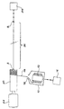
- a fixed frame (not shown) supports substantially stationary a spool 12 on which the fiber is wound single-mode optics 14 for which it is desired to test the behavior during its development.
- Reel 12 as well as the optical fiber 14 which it supports are of preferably identical to those used on the craft.
- the use of a single mode optical fiber 14 allows transmission bidirectional information in bandwidth very wide about 20 GHz.km, when the fiber is not not twisted.
- single mode optical fiber 14 may have a diameter of approximately 250 ⁇ m.
- a fixed end of the optical fiber singlemode 14 wound on the coil 12 is connected directly on a first device 16 optical transceiver.
- This device includes including a laser source and a wide photodetector bandaged.
- the laser source allows to send in the fiber optical 14 a light signal modulated in frequency according to the measurements you want to perform.
- the broadband photodetector receives signals light coming out of the optical fiber 14, for transform into electrical signals which can including being sent to a network analyzer according to known techniques, which are not part of the invention.
- the end of the single mode optical fiber 14 which takes place from the coil e 12 comes out of a case 10 surrounding the coil 12 by a passage 18 arranged according to the axis of the coil 12.
- the fiber 14 is then wound on a drum 20 placed opposite the opening 18 and whose axis is substantially perpendicular to that of coil 12.
- the drum 20 is mounted on the frame (not shown) of the test bench so that it can rotate around its axis at high speed. Its rotation is driven by a motor 22.
- the single mode optical fiber 14 comes out of the drum 20 along its axis at a point A, to be finally connected by its end, at a point B, on a second transceiver device 24 optics similar to the first device 16.
- this seal rotating optic 26 consists of a length of the single mode optical fiber 14 provided between the point of output A of drum 20 and connection point B of the fiber 14 on the second device 24 optical transceiver.
- This length A.B of the fiber. single mode optics 14 is determined based on the maximum number of turns of the rotational movement relative performed during a test between the segment of the fiber linked in A to the drum 20 and the segment of the fiber linked in B to the second transmitter-receiver device 24 optical.
- the length of the optical fiber 14 between points A and B expressed in meters, is at least equal to about N / 150, N being the maximum number of turns of the rotational movement relative above.
- twist of the fiber to 150 rpm leads to use, to form the joint rotating optic 26, 130 m of single mode optical fiber 14 if the fiber reel to be tested requires 19,500 drum turns.
- the sections of the single mode optical fiber 14 which are connected by the length A-B of the single mode optical fiber 14, forming the rotating optical joint 26 are of preferably substantially aligned and oriented according to a substantially horizontal direction. These sections may however be slightly offset one by compared to the other while remaining appreciably parallel.
- the latter arrangement is used in especially when the length A-B of the optical fiber 14 forming the rotating optical joint 26 is at least equal to about 100 m. Indeed, it generates vibrations-in optical fiber 14 between points A and B, which improve the distribution of torsion over full length.
- a misalignment of about 1 cm from the two sections of optical fiber connected by length A-B of the fiber forming the rotating optical joint 26 is sufficient to achieve this result.
- the alignment or the parallelism of the two sections of optical fiber connected by the length of fiber forming the joint rotating optic 26 is not a constraint essential to the realization of this joint.
- the length of optical fiber singlemode 14 joining points A and B to form the rotating optical seal 26 must be kept away from any obstacle.
- a certain tension is applied to fiber 14, between these two points A and B, to prevent the optical fiber from entering contact with the ground between the drum 20 and the second 24 optical transceiver device.
- no precise tension is recommended.
- the torsional failure tests already cited, were carried out at different voltages (for example 0.5 N, 1 N and 2.3 N for 1 m, 10 m, 15 m and 100 m of fiber) and did not reveal a significant effect of the voltage on the number of turns per unit length resulting in break.
- the absence of contact between the fiber and the soil depends on both the length of the fiber between points A and B and the distance between this fiber and the soil.
- the motor 22 is actuated so as to drive the drum 20 in high speed rotation.
- the rotation speed of the drum 20 is chosen so as to best simulate the unwinding of the optical fiber 14 out of the coil 12. This speed of rotation therefore depends on the diameter of the drum 20. As an illustration, a speed from 7,000 rpm to 8,000 rpm ensures the desired simulation.
- the rotating optical joint 26 in giving the length of the single mode optical fiber located between points A and B the corresponding value the length of the reel to be unwound and the diameter of the drum 20 used. More specifically, the optical seal turning 26 does not set any limit on the speed of possible rotation of the drum 20. In other words, the rotation speed of this drum is only limited by mechanical constraints related to its training.
- This last characteristic constitutes a essential advantage of the rotating optical joint 26 according to the invention with respect to known seals using lens coupling, which limit the relative rotation speed of about 100 rpm in the case of single-mode optical fibers, which is the only one ensure the transmission of information over a large bandwidth.
- the twisting of the single mode optical fiber 14 on the length A-B constituting the rotating optical joint reduces the bandwidth compared to that of the fiber not twisted, this bandwidth remains very important. Indeed, it is easily calculated that for 100 m of twisted fiber, the bandwidth is 25 GHz instead of 200 GHz for 100 m of non-twisted fiber. Since the length of twisted fiber does not exceed never a few hundred meters, the bandwidth the optical seal 26 according to the invention does not no reduction in the wavelength band between 0 and 500 MHz. These characteristics are far superior to those of optical seals traditional turning gears unidirectional as well as those of the optical joints rotating with lens coupling when these seals use multimode optical fibers to increase the maximum possible relative speed of rotation.
- Tests have also been carried out to measure the optical attenuation induced by the joint rotating optic 26 according to the invention when the length of single mode optical fiber 14 between points A and B is twisted. So, twist tests of a 100 m length of single mode optical fiber at 150 rpm and at 200 rpm have shown that the optical attenuation is around 0.5 decibel, across the entire bandwidth between 0 and 500 MHz. Optical attenuation torsional induced is therefore very acceptable and allows to keep the parameters in good conditions of transmission between the two devices 16 and 24 optical transceiver.
- a rotating optical joint 26 consisting of a length of single-mode optical fiber directly connecting the two sections of optical fiber singlemode with relative rotational motion therefore ensures a bidirectional transmission of information with a high bandwidth, in allowing a high relative speed of rotation, while maintaining the transmission parameters and with very good mechanical strength.
Landscapes
- Physics & Mathematics (AREA)
- General Physics & Mathematics (AREA)
- Optics & Photonics (AREA)
- Optical Couplings Of Light Guides (AREA)
- Light Guides In General And Applications Therefor (AREA)
- Optical Communication System (AREA)
Description
Claims (6)
- Procédé de transmission bidirectionnelle d'informations entre deux tronçons de fibre optique monomode (14). ayant un mouvement de rotation relative, comprenant les étapes suivantes :a) déterminer le nombre maximal de tours N non nul de mouvement de rotation relative entre les deux tronçons de fibre optique monomode,b) relier directement lesdits tronçons de fibre optique monomode par un joint optique tournant (26) comprenant une longueur (AB) de fibre optique monomode (14), la longueur (AB), exprimée en mètres, étant au moins égale à N/150,c) initier la rotation des deux tronçons de fibre optique monomode et transmettre les informations entre lesdits tronçons.
- Procédé selon la revendication 1, dans lequel, lorsque ladite longueur (AB) de fibre optique monomode (14) est inférieure à environ 100 m, les deux tronçons de fibre optique monomode (14) présentent des axes sensiblement confondus.
- Procédé selon la revendication 1, dans lequel, lorsque ladite longueur (AB) de fibre optique monomode (14) est au moins égale à environ 100 m, les deux tronçons de fibre optique monomode (14) présentent des axes sensiblement parallèles et décalés l'un par rapport à l'autre.
- Procédé selon l'une quelconque des revendications 1 à 3, dans lequel ladite longueur (AB) de fibre optique monomode (14) est sous tension.
- Procédé selon l'une quelconque des revendications précédentes, dans lequel ladite longueur (AB) de fibre optique monomode est sensiblement horizontale.
- Procédé selon l'une quelconque des revendications précédentes, dans lequel le joint (26) est placé dans un banc d'essai apte à réaliser un déroulement rapide d'une fibre optique bobinée (14), entre un tronçon de fibre enroulé sur un tambour (20) animé d'un mouvement de rotation rapide autour de son axe et un tronçon de fibre relié à un dispositif statique (24) émetteur-récepteur optique.
Applications Claiming Priority (2)
| Application Number | Priority Date | Filing Date | Title |
|---|---|---|---|
| FR9514474 | 1995-12-07 | ||
| FR9514474A FR2742236B1 (fr) | 1995-12-07 | 1995-12-07 | Joint optique tournant a transmission bidirectionnelle d'informations |
Publications (2)
| Publication Number | Publication Date |
|---|---|
| EP0778480A1 EP0778480A1 (fr) | 1997-06-11 |
| EP0778480B1 true EP0778480B1 (fr) | 2004-04-14 |
Family
ID=9485240
Family Applications (1)
| Application Number | Title | Priority Date | Filing Date |
|---|---|---|---|
| EP96402641A Expired - Lifetime EP0778480B1 (fr) | 1995-12-07 | 1996-12-05 | Joint optique tournant à transmission bidirectionnelle d'informations |
Country Status (5)
| Country | Link |
|---|---|
| EP (1) | EP0778480B1 (fr) |
| DE (1) | DE69632179T2 (fr) |
| ES (1) | ES2218576T3 (fr) |
| FR (1) | FR2742236B1 (fr) |
| IL (1) | IL119706A (fr) |
Citations (1)
| Publication number | Priority date | Publication date | Assignee | Title |
|---|---|---|---|---|
| EP0035054A1 (fr) * | 1980-02-28 | 1981-09-09 | AEG - TELEFUNKEN Nachrichtentechnik GmbH | Joint rotatif pour guide d'ondes optiques |
Family Cites Families (2)
| Publication number | Priority date | Publication date | Assignee | Title |
|---|---|---|---|---|
| GB8601318D0 (en) * | 1986-01-20 | 1986-02-26 | Gen Electric Co Plc | Optical fibre connectors |
| US5297225A (en) * | 1992-06-04 | 1994-03-22 | Focal Technologies Incorporated | Off-axis optical rotary joint |
-
1995
- 1995-12-07 FR FR9514474A patent/FR2742236B1/fr not_active Expired - Fee Related
-
1996
- 1996-11-27 IL IL11970696A patent/IL119706A/xx not_active IP Right Cessation
- 1996-12-05 ES ES96402641T patent/ES2218576T3/es not_active Expired - Lifetime
- 1996-12-05 DE DE69632179T patent/DE69632179T2/de not_active Expired - Fee Related
- 1996-12-05 EP EP96402641A patent/EP0778480B1/fr not_active Expired - Lifetime
Patent Citations (1)
| Publication number | Priority date | Publication date | Assignee | Title |
|---|---|---|---|---|
| EP0035054A1 (fr) * | 1980-02-28 | 1981-09-09 | AEG - TELEFUNKEN Nachrichtentechnik GmbH | Joint rotatif pour guide d'ondes optiques |
Also Published As
| Publication number | Publication date |
|---|---|
| FR2742236B1 (fr) | 1998-03-06 |
| DE69632179T2 (de) | 2004-11-11 |
| ES2218576T3 (es) | 2004-11-16 |
| FR2742236A1 (fr) | 1997-06-13 |
| IL119706A0 (en) | 1997-02-18 |
| EP0778480A1 (fr) | 1997-06-11 |
| IL119706A (en) | 2000-06-01 |
| DE69632179D1 (de) | 2004-05-19 |
Similar Documents
| Publication | Publication Date | Title |
|---|---|---|
| US5453827A (en) | Fiberoptic in-line filter and technique for measuring the transmission quality of an optical fiber through the use of a fiberoptic in-line filter | |
| JP2011515700A (ja) | 光ファイバの連続的測定システム | |
| US4996420A (en) | Measurement of optical attenuation along the length of bent optical fibers | |
| EP0072292A1 (fr) | Procédé de mesure d'un courant électrique et appareil pour sa mise en oeuvre | |
| EP0136761B1 (fr) | Procédé et dispositif pour coupler un signal optique entre un premier et un deuxième guide optique | |
| EP0018873B1 (fr) | Dispositif compact de couplage optique et gyromètre interferométrique à fibre optique comportant un tel dispositif | |
| FR2652572A1 (fr) | Procede d'enroulement en double d'un cable ou analogue sur la surface externe d'un touret. | |
| KR101348075B1 (ko) | 팬 및 틸트 회동 가능한 영상전송장치의 광 슬립링 | |
| EP0778480A1 (fr) | Joint optique tournant à transmission bidirectionnelle d'informations | |
| FR2575557A1 (fr) | Dispositif transformateur d'ouverture numerique | |
| JP2784155B2 (ja) | 光ファイバ高速繰り出し試験装置 | |
| EP0493213B1 (fr) | Dispositif de détection des irrégularités du diamétre d'un fil | |
| US20030165283A1 (en) | Device for providing polarized light | |
| US4555175A (en) | Measuring compression of cabled optical fibers | |
| EP0301941B1 (fr) | Dispositif de positionnement d'une maquette dans l'espace, notamment pour l'étude de la rétrodiffusion de cette maquette | |
| CN114562953A (zh) | 非对称双芯光纤的弯曲测量结构、实验仪器以及传感器 | |
| EP1491511A1 (fr) | Système anti-PMD pour fibres optiques | |
| FR2700612A1 (fr) | Dispositif de déroulement rapide d'une fibre optique bobinée et son application à un banc de mesures sur une fibre optique en déroulement. | |
| JP2601726B2 (ja) | ハーメチックコート光ファイバの検査方法 | |
| EP4515199B1 (fr) | Dispositif de detection d'un defaut dans un element structurel en materiau composite | |
| JPH0338207Y2 (fr) | ||
| FR2703451A1 (fr) | Dispositif de mesure interférométrique en lumière polarisée. | |
| FR2653946A1 (fr) | Procede de deroulage et de mise en place d'un cable a fibres optiques et installation pour la mise en óoeuvre de ce procede. | |
| EP1151334A1 (fr) | Dispositif d'attenuation en ligne pour fibre monomode et procede de fabrication associe | |
| CN209416383U (zh) | 一种光纤光栅传感器刻写检测定位解调装置 |
Legal Events
| Date | Code | Title | Description |
|---|---|---|---|
| PUAI | Public reference made under article 153(3) epc to a published international application that has entered the european phase |
Free format text: ORIGINAL CODE: 0009012 |
|
| AK | Designated contracting states |
Kind code of ref document: A1 Designated state(s): BE CH DE ES GB IT LI NL SE |
|
| 17P | Request for examination filed |
Effective date: 19971121 |
|
| RAP1 | Party data changed (applicant data changed or rights of an application transferred) |
Owner name: AEROSPATIALE MATRA |
|
| RAP1 | Party data changed (applicant data changed or rights of an application transferred) |
Owner name: EUROPEAN AERONAUTIC DEFENCE AND SPACE COMPANY - EA |
|
| 17Q | First examination report despatched |
Effective date: 20030530 |
|
| GRAP | Despatch of communication of intention to grant a patent |
Free format text: ORIGINAL CODE: EPIDOSNIGR1 |
|
| GRAS | Grant fee paid |
Free format text: ORIGINAL CODE: EPIDOSNIGR3 |
|
| GRAA | (expected) grant |
Free format text: ORIGINAL CODE: 0009210 |
|
| AK | Designated contracting states |
Kind code of ref document: B1 Designated state(s): BE CH DE ES GB IT LI NL SE |
|
| REG | Reference to a national code |
Ref country code: GB Ref legal event code: FG4D Free format text: NOT ENGLISH |
|
| REG | Reference to a national code |
Ref country code: CH Ref legal event code: EP |
|
| REF | Corresponds to: |
Ref document number: 69632179 Country of ref document: DE Date of ref document: 20040519 Kind code of ref document: P |
|
| REG | Reference to a national code |
Ref country code: SE Ref legal event code: TRGR |
|
| GBT | Gb: translation of ep patent filed (gb section 77(6)(a)/1977) |
Effective date: 20040714 |
|
| REG | Reference to a national code |
Ref country code: ES Ref legal event code: FG2A Ref document number: 2218576 Country of ref document: ES Kind code of ref document: T3 |
|
| PLBE | No opposition filed within time limit |
Free format text: ORIGINAL CODE: 0009261 |
|
| STAA | Information on the status of an ep patent application or granted ep patent |
Free format text: STATUS: NO OPPOSITION FILED WITHIN TIME LIMIT |
|
| 26N | No opposition filed |
Effective date: 20050117 |
|
| PGFP | Annual fee paid to national office [announced via postgrant information from national office to epo] |
Ref country code: ES Payment date: 20061128 Year of fee payment: 11 |
|
| PGFP | Annual fee paid to national office [announced via postgrant information from national office to epo] |
Ref country code: GB Payment date: 20061129 Year of fee payment: 11 |
|
| PGFP | Annual fee paid to national office [announced via postgrant information from national office to epo] |
Ref country code: NL Payment date: 20061203 Year of fee payment: 11 |
|
| PGFP | Annual fee paid to national office [announced via postgrant information from national office to epo] |
Ref country code: SE Payment date: 20061206 Year of fee payment: 11 |
|
| PGFP | Annual fee paid to national office [announced via postgrant information from national office to epo] |
Ref country code: CH Payment date: 20061221 Year of fee payment: 11 |
|
| PGFP | Annual fee paid to national office [announced via postgrant information from national office to epo] |
Ref country code: DE Payment date: 20061223 Year of fee payment: 11 |
|
| PGFP | Annual fee paid to national office [announced via postgrant information from national office to epo] |
Ref country code: IT Payment date: 20061231 Year of fee payment: 11 |
|
| PGFP | Annual fee paid to national office [announced via postgrant information from national office to epo] |
Ref country code: BE Payment date: 20070222 Year of fee payment: 11 |
|
| BERE | Be: lapsed |
Owner name: EUROPEAN AERONAUTIC DEFENCE AND SPACE CY - *EADS F Effective date: 20071231 |
|
| REG | Reference to a national code |
Ref country code: CH Ref legal event code: PL |
|
| EUG | Se: european patent has lapsed | ||
| GBPC | Gb: european patent ceased through non-payment of renewal fee |
Effective date: 20071205 |
|
| NLV4 | Nl: lapsed or anulled due to non-payment of the annual fee |
Effective date: 20080701 |
|
| PG25 | Lapsed in a contracting state [announced via postgrant information from national office to epo] |
Ref country code: BE Free format text: LAPSE BECAUSE OF NON-PAYMENT OF DUE FEES Effective date: 20071231 |
|
| PG25 | Lapsed in a contracting state [announced via postgrant information from national office to epo] |
Ref country code: SE Free format text: LAPSE BECAUSE OF NON-PAYMENT OF DUE FEES Effective date: 20071206 Ref country code: LI Free format text: LAPSE BECAUSE OF NON-PAYMENT OF DUE FEES Effective date: 20071231 Ref country code: DE Free format text: LAPSE BECAUSE OF NON-PAYMENT OF DUE FEES Effective date: 20080701 Ref country code: CH Free format text: LAPSE BECAUSE OF NON-PAYMENT OF DUE FEES Effective date: 20071231 |
|
| PG25 | Lapsed in a contracting state [announced via postgrant information from national office to epo] |
Ref country code: NL Free format text: LAPSE BECAUSE OF NON-PAYMENT OF DUE FEES Effective date: 20080701 |
|
| PG25 | Lapsed in a contracting state [announced via postgrant information from national office to epo] |
Ref country code: GB Free format text: LAPSE BECAUSE OF NON-PAYMENT OF DUE FEES Effective date: 20071205 |
|
| REG | Reference to a national code |
Ref country code: ES Ref legal event code: FD2A Effective date: 20071207 |
|
| PG25 | Lapsed in a contracting state [announced via postgrant information from national office to epo] |
Ref country code: ES Free format text: LAPSE BECAUSE OF NON-PAYMENT OF DUE FEES Effective date: 20071207 |
|
| PG25 | Lapsed in a contracting state [announced via postgrant information from national office to epo] |
Ref country code: IT Free format text: LAPSE BECAUSE OF NON-PAYMENT OF DUE FEES Effective date: 20071205 |