EP0778603A2 - Fusible plat et méthode pour sa fabrication - Google Patents
Fusible plat et méthode pour sa fabrication Download PDFInfo
- Publication number
- EP0778603A2 EP0778603A2 EP96119372A EP96119372A EP0778603A2 EP 0778603 A2 EP0778603 A2 EP 0778603A2 EP 96119372 A EP96119372 A EP 96119372A EP 96119372 A EP96119372 A EP 96119372A EP 0778603 A2 EP0778603 A2 EP 0778603A2
- Authority
- EP
- European Patent Office
- Prior art keywords
- fuse
- grooves
- strips
- fusible
- strip
- Prior art date
- Legal status (The legal status is an assumption and is not a legal conclusion. Google has not performed a legal analysis and makes no representation as to the accuracy of the status listed.)
- Granted
Links
- 238000004519 manufacturing process Methods 0.000 title claims description 9
- 238000000034 method Methods 0.000 title claims description 7
- 239000002245 particle Substances 0.000 abstract description 8
- 238000003825 pressing Methods 0.000 description 6
- 238000005530 etching Methods 0.000 description 4
- 238000010438 heat treatment Methods 0.000 description 4
- 230000008016 vaporization Effects 0.000 description 4
- 238000009834 vaporization Methods 0.000 description 3
- 238000004026 adhesive bonding Methods 0.000 description 2
- 230000004048 modification Effects 0.000 description 2
- 238000012986 modification Methods 0.000 description 2
- 230000000717 retained effect Effects 0.000 description 2
- 238000000926 separation method Methods 0.000 description 2
- 239000004020 conductor Substances 0.000 description 1
- 238000005520 cutting process Methods 0.000 description 1
- 230000005611 electricity Effects 0.000 description 1
- 239000010408 film Substances 0.000 description 1
- 238000003780 insertion Methods 0.000 description 1
- 230000037431 insertion Effects 0.000 description 1
- 238000005304 joining Methods 0.000 description 1
- 230000014759 maintenance of location Effects 0.000 description 1
- 239000000155 melt Substances 0.000 description 1
- 239000002184 metal Substances 0.000 description 1
- 239000011347 resin Substances 0.000 description 1
- 229920005989 resin Polymers 0.000 description 1
- 230000000630 rising effect Effects 0.000 description 1
- 239000010409 thin film Substances 0.000 description 1
- 238000003466 welding Methods 0.000 description 1
Images


Classifications
-
- H—ELECTRICITY
- H01—ELECTRIC ELEMENTS
- H01H—ELECTRIC SWITCHES; RELAYS; SELECTORS; EMERGENCY PROTECTIVE DEVICES
- H01H85/00—Protective devices in which the current flows through a part of fusible material and this current is interrupted by displacement of the fusible material when this current becomes excessive
- H01H85/02—Details
- H01H85/04—Fuses, i.e. expendable parts of the protective device, e.g. cartridges
- H01H85/041—Fuses, i.e. expendable parts of the protective device, e.g. cartridges characterised by the type
- H01H85/0411—Miniature fuses
-
- H—ELECTRICITY
- H01—ELECTRIC ELEMENTS
- H01H—ELECTRIC SWITCHES; RELAYS; SELECTORS; EMERGENCY PROTECTIVE DEVICES
- H01H69/00—Apparatus or processes for the manufacture of emergency protective devices
- H01H69/02—Manufacture of fuses
Definitions
- the present Invention relates to a planar fuse in which a fusing path having a prescribed conductive capacity is disposed on the surface of an insulative base.
- the present Invention also relates to a method for making the fuse.
- the fusing path is circuit 2 formed of a thin metallic film adhered to the surface of insulative base 1 by etching and vaporization.
- electricity passes through circuit 2 on the surface of insulating base 1; when the prescribed electrical capacity is exceeded, the thin film heats up and melts, thereby breaking the circuit.
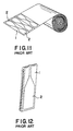
- a blade-shaped fuse is shown. While not planar, it is similar to the foregoing fuse.
- a shape is molded to form two thick plates 3,3 serving as terminals, and string-shaped fusing path 4 connects the two thick plates.
- Resin 5 covers the outside.
- the prior art fuses described above have a number of problems.
- a plurality of such fuses is arranged to provide circuits, foreign particles can impact on the fuse causing it to peel away, thus creating the possibility of a short-circuit with a neighboring fuse.
- the circuit is formed by etching and vaporization, wet production is necessary, thus requiring a difficult operating environment.
- the object of the present Invention is to overcome the problems of the prior art described above.
- a further object of the present Invention is to provide a planar fuse which prevents short circuits between adjacent conductors, does not require wet processes in manufacturing, and is easy to manufacture.
- fusing paths are arranged in parallel rows on the insulative base, with a separation between each path. Thus, if a foreign particle impacts a path, it may peel off, but it will not go past the separation to come into contact with an adjacent fusing path.
- the paths have a predetermined capacity and are mounted between projections formed on the surface of the insulative base.
- the portion that is to come into contact with external electrodes and the like has a large exposed area, and the portion that will not come into contact has little or no exposed area.
- the large exposure area at the uncovered portion enhances the ability to act as contact surfaces for electrodes and the like, while the little or no exposure areas protect the fuse from foreign particles.
- the surfaces of the projections slope upward toward the edges of the fusing paths. When the projections are pressed flat, they bear against the fusing paths and the under surfaces of the projections cover at least the edges thereof.
- the fusing path passes over a cavity in the base and is suspended in mid-air. This prevents heat generated in the fusing path from being dissipated into the insulative base. Thus, the heat from the portion of the fusing path that is suspended in mid-air is not absorbed, allowing heat build-up and fusing as desired.
- the base is folded so that the fusing path on its surface forms a circuit from one side of the base to the other.
- the fusing paths can be placed in prescribed circuits by inserting the edge of the base at the fold line into a socket comprising terminals that come into contact therewith on both sides of the base.
- the present Invention as described above, provides a planar fuse that prevents fusing paths from short-circuiting since adjacent paths are isolated from each other by separating walls.
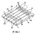
- FIG. 1 and 2 five circuits are arranged in parallel on the surface of insulative base 20 to form planar fuse 10. Fusible strips 30 are in grooves 22 and are folded back at a point midway between their ends. Windows 21 are formed toward the center of base 20 where it intersects the circuits. Each strip 30 is suspended in mid-air at window 21, has a predetermined electrical capacity depending on its cross-section, and is designed so that it fuses when the electric current flow exceeds this capacity. Thus, the circuits serve as fusing paths.
- Insulative base 20 is bent in two at fold line 11 in a manner resembling two hands held together in prayer.
- base 20 does not need to be bent over, and can be flat as long as the circuits can be arranged on the surface.
- windows 21 it is not absolutely necessary to have windows 21.
- fusible strips 30 can be suspended mid-air. This prevents the heat generated in strips 30 from being absorbed by base 20, thereby allowing the suspended portion to melt more easily and more accurately.
- windows 21 are cavities.
- windows 21 do not need to be continuous; it is sufficient if they are cavities which allow strips 30 to be out of contact with base 20 at one point.
- strips 30 need not have a planar cross-section; the shape can be e.g. circular or trapezoidal in cross-section, as long as they can be affixed to the base.
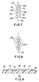
- grooves 22 correspond to the location of strips 30. Separating walls 23 are on either side of each groove 22.
- the surface of separating wall 23 is sloped so that the ends adjacent groove 22 project upward.
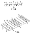
- Strips 30 are mounted in grooves 22 and projecting portions 6 are pressed downward. As can be seen in Figures 5 and 6, the pressed portions bear against and retain the edges of strips 30.
- separating wall 23 In this embodiment, the entire surface of separating wall 23 is pressed. However, separating walls 23 need only cover and apply pressure to the edges of adjacent strips 30. Therefore, it is possible to form projections 24a at various points on separating wall 24, as shown in Figure 7. Projections 24a are then pressed to provide localized pressure on - and retention of - strips 30. Of course, the cross-section of the projection does not need to have the particular sloped form described above.
- the surface of separating wall 23 is flat throughout and still prevents the edges of strips 30 from rising out of groove 22. In terms of strength, the embodiment of Figure 5 is stronger, but the flat structure shown in Figure 9 can be used as well, depending on the amount of strength required.
- Separating wall 23 need not be formed uniformly on base 20. At the portions near the ends of the base, separating walls 23 are spaced apart from groove 22. As shown in Figure 6, when pressure is exerted on the base, thereby crushing separating walls 23, the walls in this region are not pushed into groove 22 and do not overlie the edges of strips 30.
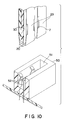
- the fuse is inserted into socket 50 through slit 51.
- Metal terminals 52, 52 are supported by slit 51 so that they face each other and are adapted to contact the surfaces of strips 30 at windows 7. This provides a wide area of contact, insuring that good electrical connection will result; at the same time, for protection, the other portions are exposed only slightly.
- base 20 is bent in two at fold line 11 to complete fuse 10.
- fusible strip 30 is mounted in groove 22 in base 20. Retaining projections 6 on wall 23 adjacent grooves 22 are crushed as by high-frequency welding, heating, or high-frequency heating, and the edges of strips 30 are held and retained thereby. Thus, it is not necessary to perform any wet production processes such as etching, vaporization, or gluing, thereby making production very efficient. It is also possible to form a bend beforehand, and fix the parts through heating. Fixing can be performed without heating by forming interlocking cavities and projections to facilitate engagement, and then joining the parts.
- wall 23 is formed between adjacent grooves 22 on the surface of base 20 and circuits comprising fusible strips 30 are mounted therein. By crushing separating wall 23, strips 30 are pressed down and retained. If a foreign particle impacts fuse 10, it will not short-circuit with an adjacent strip 30 even if it starts to peel off.
Landscapes
- Engineering & Computer Science (AREA)
- Manufacturing & Machinery (AREA)
- Fuses (AREA)
Applications Claiming Priority (3)
| Application Number | Priority Date | Filing Date | Title |
|---|---|---|---|
| JP34495995A JP3216511B2 (ja) | 1995-12-05 | 1995-12-05 | 板状ヒューズおよび板状ヒューズの製造方法 |
| JP344959/95 | 1995-12-05 | ||
| JP34495995 | 1995-12-05 |
Publications (3)
| Publication Number | Publication Date |
|---|---|
| EP0778603A2 true EP0778603A2 (fr) | 1997-06-11 |
| EP0778603A3 EP0778603A3 (fr) | 1997-10-22 |
| EP0778603B1 EP0778603B1 (fr) | 2001-11-07 |
Family
ID=18373317
Family Applications (1)
| Application Number | Title | Priority Date | Filing Date |
|---|---|---|---|
| EP96119372A Expired - Lifetime EP0778603B1 (fr) | 1995-12-05 | 1996-12-03 | Fusible plat et méthode pour sa fabrication |
Country Status (4)
| Country | Link |
|---|---|
| US (1) | US5781096A (fr) |
| EP (1) | EP0778603B1 (fr) |
| JP (1) | JP3216511B2 (fr) |
| DE (1) | DE69616722D1 (fr) |
Families Citing this family (9)
| Publication number | Priority date | Publication date | Assignee | Title |
|---|---|---|---|---|
| US5805048A (en) * | 1995-09-01 | 1998-09-08 | Sumitomo Wiring Systems, Ltd. | Plate fuse and method of producing the same |
| JP2004047375A (ja) * | 2002-07-15 | 2004-02-12 | Yazaki Corp | 連鎖ヒューズ及びヒューズ組み込み方法 |
| JP4009515B2 (ja) * | 2002-10-02 | 2007-11-14 | 矢崎総業株式会社 | ヒュージブルリンクユニット |
| US20070018774A1 (en) * | 2005-07-20 | 2007-01-25 | Dietsch Gordon T | Reactive fuse element with exothermic reactive material |
| KR100799737B1 (ko) * | 2006-06-16 | 2008-02-01 | 삼성전자주식회사 | 퓨즈 구조물 및 그 형성 방법 |
| US7983024B2 (en) * | 2007-04-24 | 2011-07-19 | Littelfuse, Inc. | Fuse card system for automotive circuit protection |
| US8971006B2 (en) * | 2011-02-04 | 2015-03-03 | Denso Corporation | Electronic control device including interrupt wire |
| JP2012164755A (ja) | 2011-02-04 | 2012-08-30 | Denso Corp | 電子制御装置 |
| US10314176B2 (en) * | 2013-01-08 | 2019-06-04 | Honeywell Federal Manufacturing & Technologies, Llc | Contact assembly |
Citations (1)
| Publication number | Priority date | Publication date | Assignee | Title |
|---|---|---|---|---|
| JPS5638959A (en) | 1979-08-31 | 1981-04-14 | Matsushita Electric Works Ltd | Brush for dc motor |
Family Cites Families (11)
| Publication number | Priority date | Publication date | Assignee | Title |
|---|---|---|---|---|
| DE130288C (fr) * | ||||
| JPS5286148A (en) * | 1976-01-13 | 1977-07-18 | Shinagawa Jidosha Densen | Fuse board |
| DE2630697A1 (de) * | 1976-07-08 | 1978-01-19 | Grote & Hartmann | Flachsicherung |
| DE2729452C3 (de) * | 1977-06-30 | 1980-06-12 | Grote & Hartmann Gmbh & Co Kg, 5600 Wuppertal | Flachsicherung |
| AU518330B2 (en) * | 1977-07-07 | 1981-09-24 | Amp Incorporated | Fuse |
| JPS5638959U (fr) * | 1979-09-03 | 1981-04-11 | ||
| KR910002070B1 (ko) * | 1982-07-07 | 1991-04-01 | 유끼노부 와다나베 | 통형퓨우즈 |
| JPS6114625A (ja) * | 1984-06-29 | 1986-01-22 | Canon Inc | フイルムコマ数表示装置 |
| DE3530354A1 (de) * | 1985-08-24 | 1987-03-05 | Opel Adam Ag | Elektrische sicherungsanordnung |
| US4680568A (en) * | 1986-04-29 | 1987-07-14 | Amp Incorporated | Electrical component having fuse element, and method of using same |
| DE8801878U1 (de) * | 1988-02-13 | 1988-04-07 | Akyürek, Altan, Dipl.-Ing., 8560 Lauf | Elektrische Sicherungseinrichtung |
-
1995
- 1995-12-05 JP JP34495995A patent/JP3216511B2/ja not_active Expired - Fee Related
-
1996
- 1996-12-03 EP EP96119372A patent/EP0778603B1/fr not_active Expired - Lifetime
- 1996-12-03 DE DE69616722T patent/DE69616722D1/de not_active Expired - Lifetime
- 1996-12-04 US US08/759,530 patent/US5781096A/en not_active Expired - Lifetime
Patent Citations (1)
| Publication number | Priority date | Publication date | Assignee | Title |
|---|---|---|---|---|
| JPS5638959A (en) | 1979-08-31 | 1981-04-14 | Matsushita Electric Works Ltd | Brush for dc motor |
Also Published As
| Publication number | Publication date |
|---|---|
| EP0778603B1 (fr) | 2001-11-07 |
| JP3216511B2 (ja) | 2001-10-09 |
| US5781096A (en) | 1998-07-14 |
| JPH09161648A (ja) | 1997-06-20 |
| DE69616722D1 (de) | 2001-12-13 |
| EP0778603A3 (fr) | 1997-10-22 |
Similar Documents
| Publication | Publication Date | Title |
|---|---|---|
| US4837546A (en) | Fuse block | |
| US5841338A (en) | Fuse combination, method of making the same, and fuse circuit including the same | |
| RU2198448C2 (ru) | Плавкий элемент многоэлектродного типа и плавкий предохранитель многоэлектродного типа (варианты) | |
| US5581225A (en) | One-piece female blade fuse with housing | |
| CN101578679B (zh) | 用于车辆的多保险丝装置 | |
| EP1336978B1 (fr) | Fusible a lame | |
| US4504816A (en) | Blade fuse and manufacturing method | |
| US5781096A (en) | Planar fuse and method for making the same | |
| JPH0644446B2 (ja) | 差込み式ヒュ−ズ装置 | |
| JPH05205608A (ja) | ヒューズ組立体 | |
| US4056884A (en) | Method of making a miniature plug-in fuse | |
| JPH07297562A (ja) | ジャンクションボックス及びその基板組立体 | |
| US4040175A (en) | Method of making a miniature plug-in fuse with fragile fuse link | |
| US5091712A (en) | Thin film fusible element | |
| EP0802553B1 (fr) | Combinaison de fusible, procédé de sa production, et circuit de fusible l'intégrant | |
| TWI874551B (zh) | 限流保險絲及其製造方法 | |
| JPH0950868A (ja) | コード付き電源プラグ | |
| JP2849886B2 (ja) | バスバーの固定方法 | |
| EP0259926B1 (fr) | Fusible | |
| JPS6231466B2 (fr) | ||
| GB2113489A (en) | Current-conducting parts for plug-in fuses | |
| JPS596608Y2 (ja) | 小型ヒユ−ズ | |
| CN222015332U (zh) | 一种受控热熔切断器 | |
| JP3377327B2 (ja) | 成型プラグ | |
| GB2233840A (en) | Electrical fuse |
Legal Events
| Date | Code | Title | Description |
|---|---|---|---|
| PUAI | Public reference made under article 153(3) epc to a published international application that has entered the european phase |
Free format text: ORIGINAL CODE: 0009012 |
|
| AK | Designated contracting states |
Kind code of ref document: A2 Designated state(s): DE FR GB |
|
| 17P | Request for examination filed |
Effective date: 19970526 |
|
| PUAL | Search report despatched |
Free format text: ORIGINAL CODE: 0009013 |
|
| AK | Designated contracting states |
Kind code of ref document: A3 Designated state(s): DE FR GB |
|
| 17Q | First examination report despatched |
Effective date: 20000508 |
|
| GRAG | Despatch of communication of intention to grant |
Free format text: ORIGINAL CODE: EPIDOS AGRA |
|
| GRAG | Despatch of communication of intention to grant |
Free format text: ORIGINAL CODE: EPIDOS AGRA |
|
| GRAH | Despatch of communication of intention to grant a patent |
Free format text: ORIGINAL CODE: EPIDOS IGRA |
|
| GRAH | Despatch of communication of intention to grant a patent |
Free format text: ORIGINAL CODE: EPIDOS IGRA |
|
| GRAA | (expected) grant |
Free format text: ORIGINAL CODE: 0009210 |
|
| AK | Designated contracting states |
Kind code of ref document: B1 Designated state(s): DE FR GB |
|
| PG25 | Lapsed in a contracting state [announced via postgrant information from national office to epo] |
Ref country code: FR Free format text: LAPSE BECAUSE OF FAILURE TO SUBMIT A TRANSLATION OF THE DESCRIPTION OR TO PAY THE FEE WITHIN THE PRESCRIBED TIME-LIMIT Effective date: 20011107 |
|
| REF | Corresponds to: |
Ref document number: 69616722 Country of ref document: DE Date of ref document: 20011213 |
|
| REG | Reference to a national code |
Ref country code: GB Ref legal event code: IF02 |
|
| PG25 | Lapsed in a contracting state [announced via postgrant information from national office to epo] |
Ref country code: GB Free format text: LAPSE BECAUSE OF NON-PAYMENT OF DUE FEES Effective date: 20020207 |
|
| PG25 | Lapsed in a contracting state [announced via postgrant information from national office to epo] |
Ref country code: DE Free format text: LAPSE BECAUSE OF FAILURE TO SUBMIT A TRANSLATION OF THE DESCRIPTION OR TO PAY THE FEE WITHIN THE PRESCRIBED TIME-LIMIT Effective date: 20020208 |
|
| EN | Fr: translation not filed | ||
| PLBE | No opposition filed within time limit |
Free format text: ORIGINAL CODE: 0009261 |
|
| STAA | Information on the status of an ep patent application or granted ep patent |
Free format text: STATUS: NO OPPOSITION FILED WITHIN TIME LIMIT |
|
| GBPC | Gb: european patent ceased through non-payment of renewal fee |
Effective date: 20020207 |
|
| 26N | No opposition filed |